patent · US3122663
Magnetohydrodynamic generator
25 February 1964
Page 1
Drawing sheet — no readable text.
Page 2
Drawing sheet — no readable text.
Page 3
Drawing sheet — no readable text.
Page 4
Drawing sheet — no readable text.
Page 5
Drawing sheet — no readable text.
Page 6
United States Patent Office 3,122,663 Patented Feb. 25, 1964
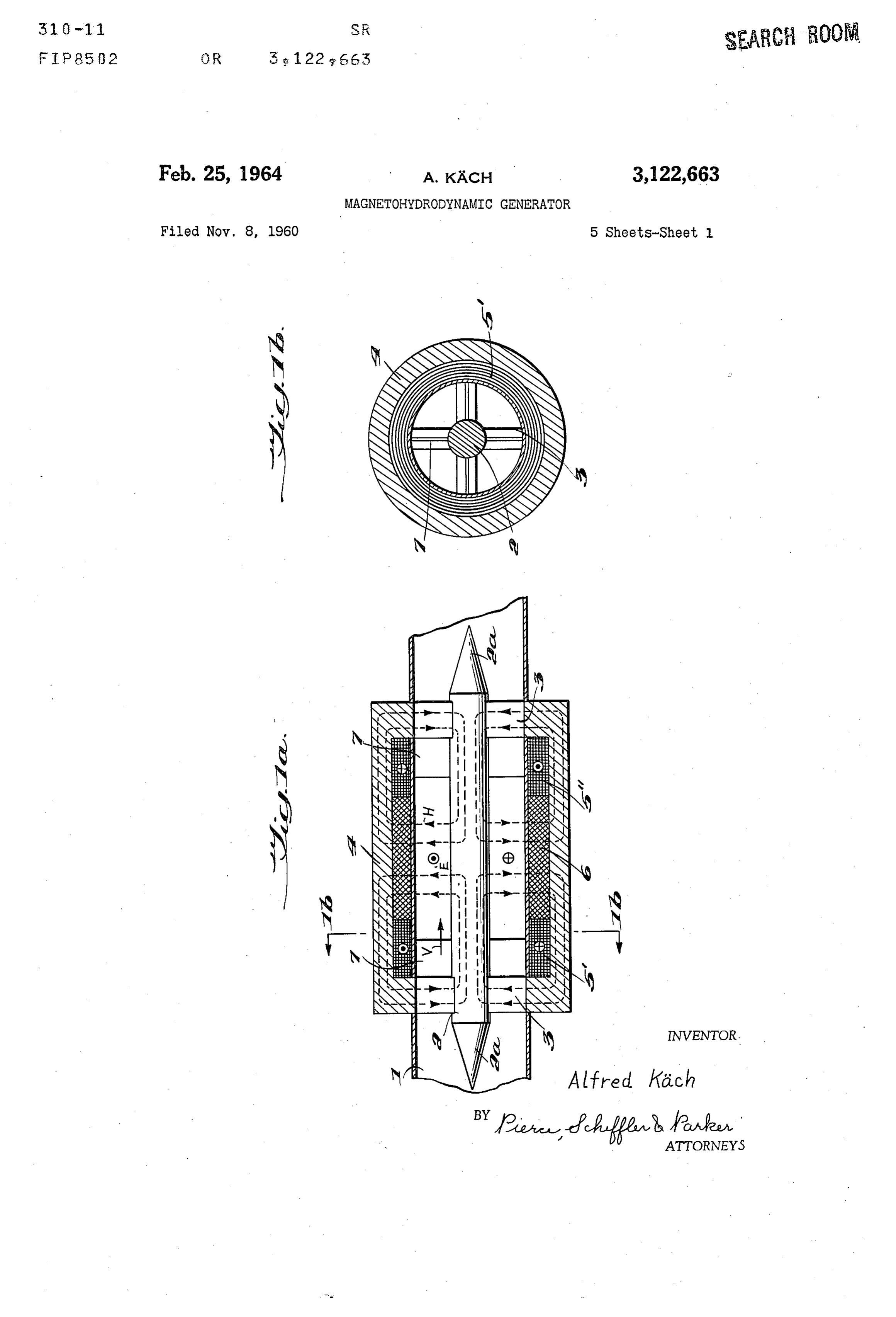
FIG. 1b is transverse sectional view taken on line
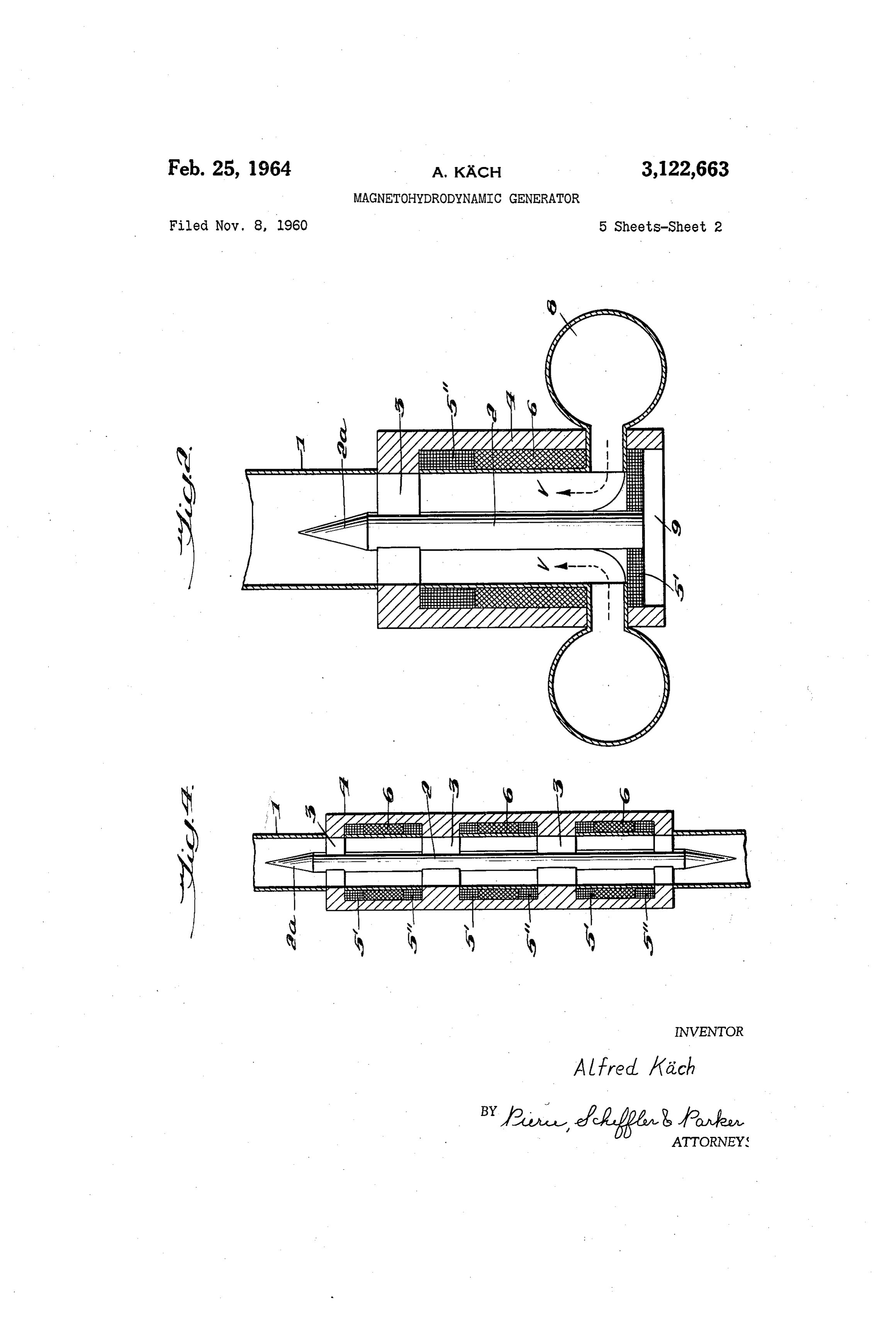
MAGNETOHYDRODYNAMC GENERATOR FIG. 2 is also a longitudinal central section view of a Alfred Kiich, Nussbaumen, near Baden, Switzerland, assignor to Aktiengesellschaft Brown, Boveri & Cie, 5 chambers construction modified are utilized wherein a plurality of combustion to supply hot ionized gas for flow
Baden, Switzerland, a joint-stock company through the spaces between the central core in the chan Fied Nov. 8, 1960, Ser. No. 68,064 nel and the magnetic shell surrounding the same, the Claims priority, application Switzerland Nov. 14, 1959 combustion gas entering the space in a radial direction
and then turning 90 to pass longitudinally through the
This invention relates to electrical generators and more O space between the core and shell.
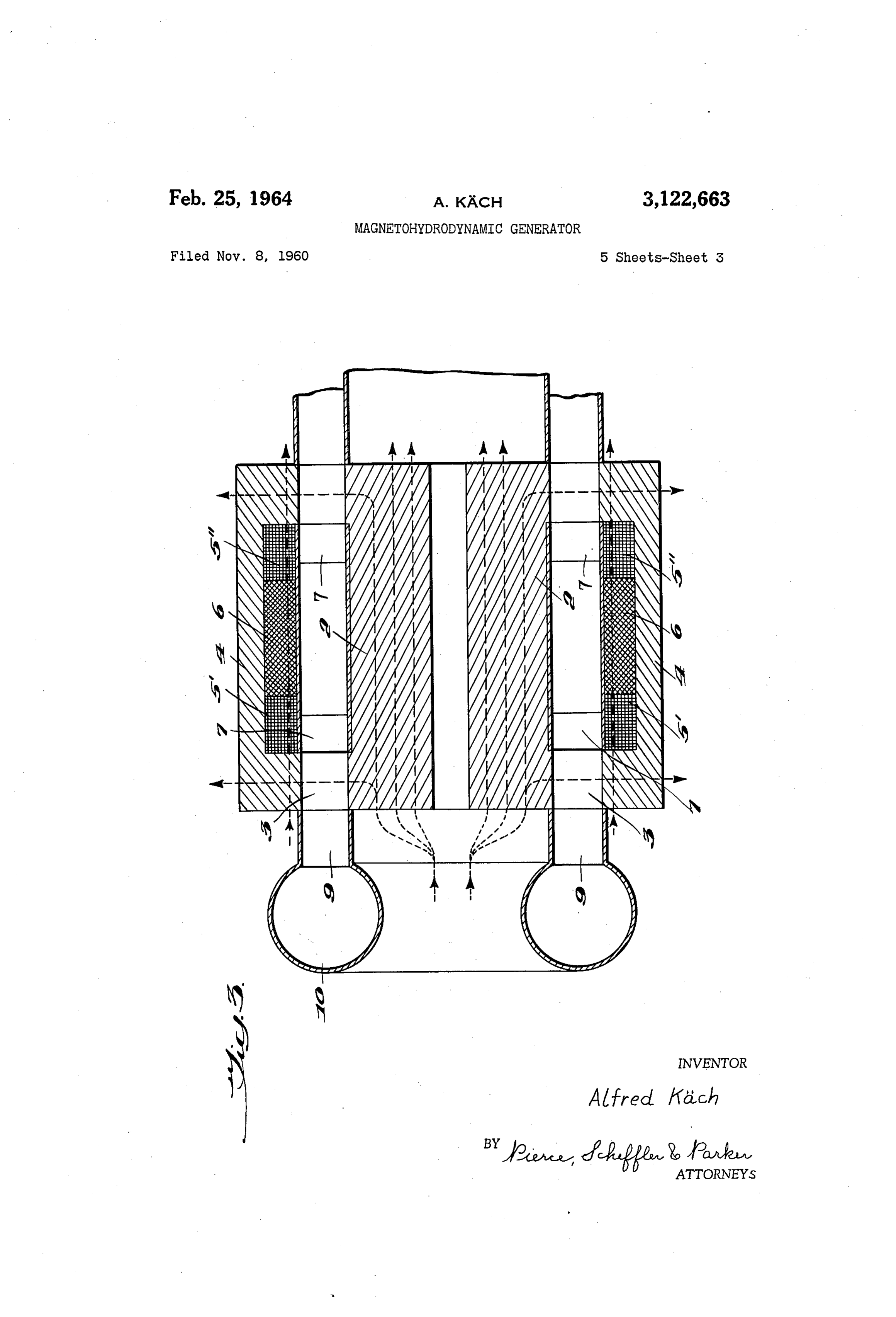
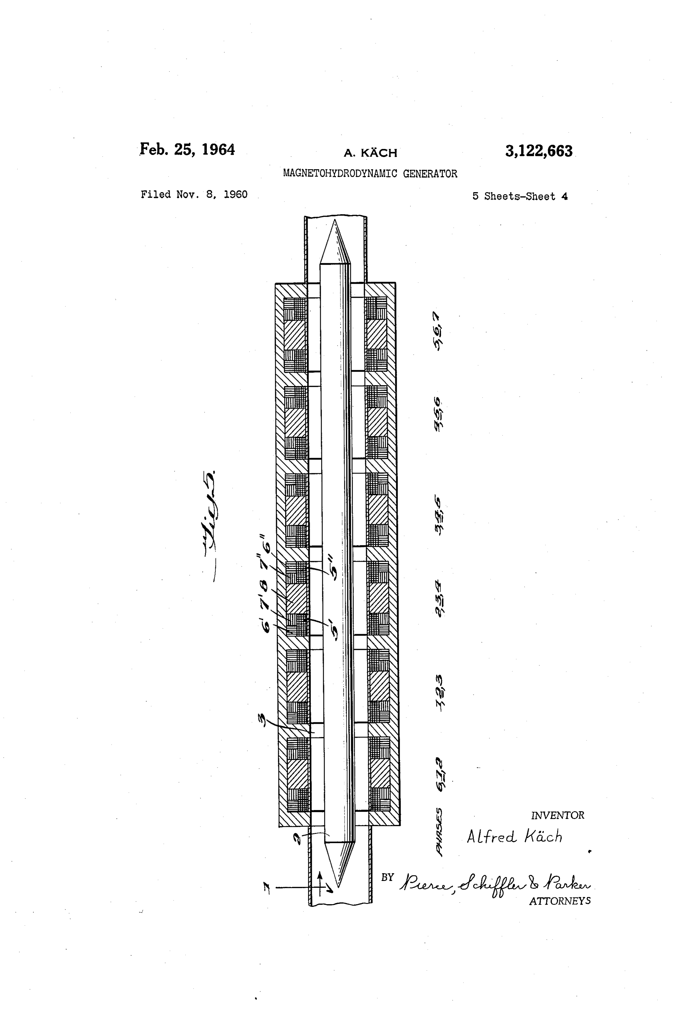
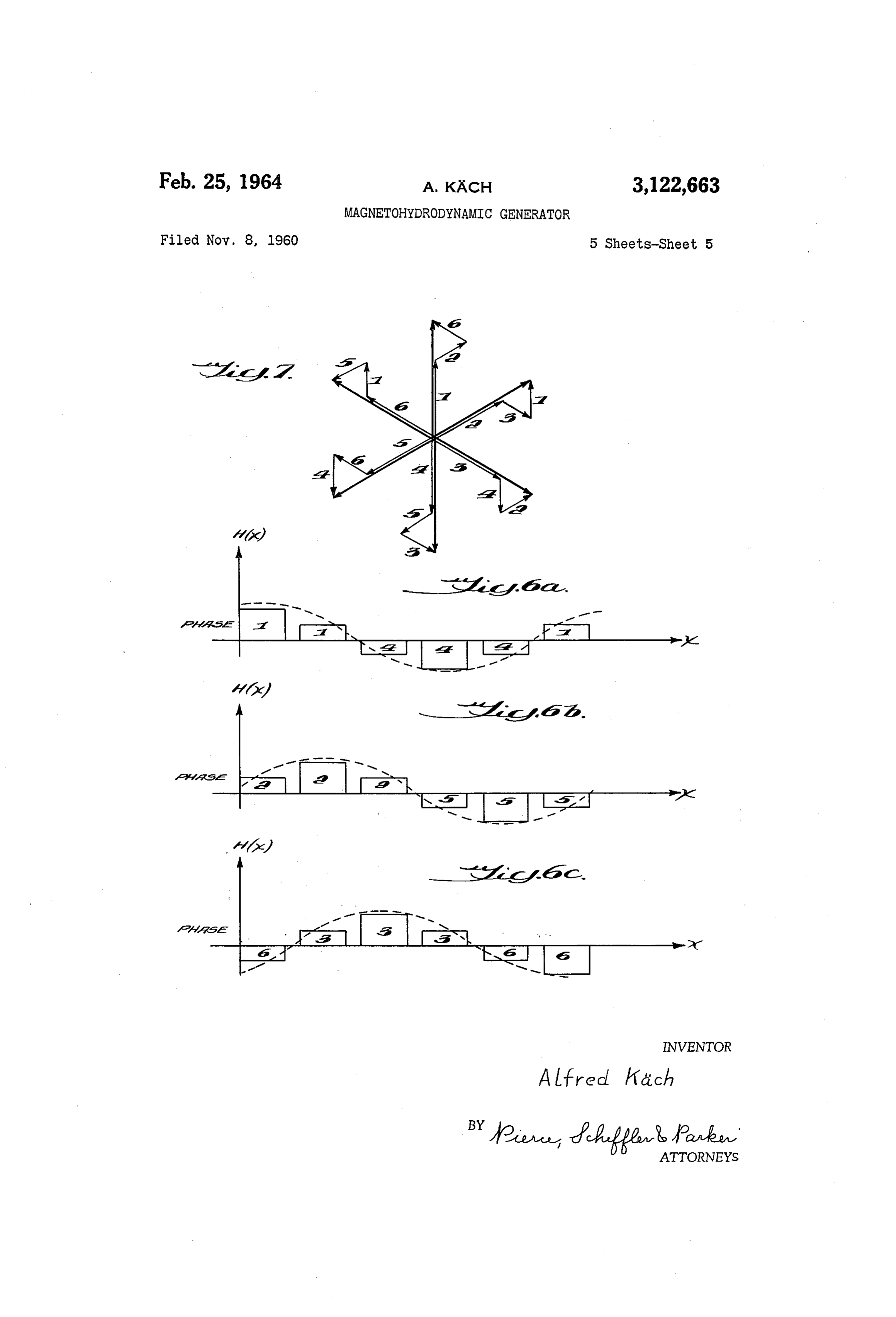
particularly to generators of the "magnetohydrodynamic' FIG. 3 is likewise a longitudinal central section view type wherein an electrical output is generated by direct of still another embodiment of the invention wherein the conversion from a heat output in the form of a high combustion chamber for supplying the hot gaseous fluid velocity heated ionized gaseous fluid. has a toroidal configuration and is located at one end of Magnetohydrodynamic generators which have been the passageway between the core and shell, there being proposed prior to the present invention include a chan provided branch pipes leading from various take-off nel through which is passed a hot ionized gas, means for points around the periphery of the toroidal chamber to generating a magnetic field extending transversely to the various parts of the passageway; direction of flow of gas in the channel, and electrodes FIG. 4 is also a longitudinal central section view of located within the channel for taking off the electrical 20 yet another embodiment of the invention similar in con power generated in the direct conversion process by sepa struction to that of FIG. 1a but which is designed for the ration of the electric charge carriers in the magnetic field. production of polyphase alternating current; One such arrangement is disclosed in my co-pending FIG. 5 is also a longitudinal central section view simi United States application Serial No. 49,523 filed August lar to that of FIG. 4 but applied to a six phase alter 15, 1960. m 25 nating current system;
The production of the electrodes involves particular FIGS. 6a to 6c are schematic representations showing difficulties. In view of the high gas temperature, usually the distribution of the individual magnetic systems pro a combustion chamber is provided as source of the gas vided by the six phases of the polyphase system according stream, a possible electrode material is, for example, car to FIG. 5, and bon. The burning down of the electrodes in operation re 30 FIG. 7 is a vector diagram illustrating the time sequence quires electrode feeding devices, with all the complica of the individual phases of the six phase system of FIG. 5. tions which they involve. For generators of the size now The construction and operation of a generator in ac considered to be particularly economical, currents in the cordance with the invention will now be further explained order of magnitude of 105 amperes must be tapped from with reference to the embodiment shown in FIGS. 1a the movable electrodes. But even if these problems were 35 and 1b.
solved satisfactorily in the practice, there would still re The magnetic structure includes a central core 2 of main additional difficulties connected with the electrodes, circular cross-section, a shell 4 of annular cross-section of which only self-emission will be mentioned here. surrounding the core, and a plurality of radial “spokes' 3 The present invention relates to an improved construc 40 Serving as connections between the core and shell to tion for a magnetohydrodynamic generator which requires carry the magnetic flux between the two. Channel 1, in no electrodes. Therefore, the enumerated difficulties do which the gas flows in the direction V, extends in the not appear. This generator directly furnishes alternating active part of the generator between core 2 and shell 4; current, so that the transformation necessary for direct thus it presents at this point an annular cross-section. In current generators, which in view of the extremely great 45 order now to let an electric field E be generated whose primary currents is likewise difficult to carry out, is elimi self-enclosed electric lines of force surround the core 2, it nated entirely. The inventive idea provides applying a is necessary to apply a magnetic field H. passing radially magnetic field which in the ionized gas stream brings through the channel. An adequately formed magnetic about forcibly the formation of an electric field of a field, whose lines of force have approximately the course strength variable in time and having self-enclosed electric 50 shown in broken lines in FIG. 1a, is generated by the two lines of force, and using the self-enclosed lines of force windings 5' and 5'. For this purpose these two windings as the "primary winding' of a transformer whose second must be traversed by the exciter current in opposite direc alry winding serves for the delivery of the generator power. tions. If the magnetic field is excited with alternating cur Accordingly, the magnetohydrodynamic generator of the rent, then also the resulting electric field surrounding core invention is characterized in that the channel presents 55 2primary is an alternating field, whose line integral represents the voltage of the shell transformer. Therefore, an
Substantially an annular cross-section and extends be tween the core and shell of at least one magnetic structure alternating current voltage can be tapped at the secondary composed in the manner of a shell transformer, present winding 6. Because of the opposite direction of feed of ing oppositely fed windings for the generation of a mag the windings 5", 5', these are decoupled in relation to netic field passing radially through the channel, and a 60 the induction flux in the transformer and hence also in relation to the secondary winding 6. The induction flux secondary winding for the tapping of the generated alter lags behind the exciter flux by 90 in phase, so that rela nating current power. tively high core inductions are permissible for both fluxes. Various constructions and arrangements are possible within the inventive concept which will be described here The cally walls of the channel must be provided with electri insulating covering at least in the active part of the inafter in further detail, and these are illustrated in the 65 generator. Adequate cooling must be provided to make accompanying drawings. Sure that nowhere in the magnetic structure the Curie FIG. 1a of the drawings illustrates an embodiment of point is reached. In view of the high velocity of the gas the inventive concept in longitudinal central section flow, the core 2 and spokes 3 in particular must be so wherein the ionized gas is admitted to the magnetic struc designed that minimal flow resistances result. This meas ture in an axial direction through the channel from a O ure is indicated in FIG. 1a as a tapering of both ends 2a combustion chamber source; of core 2. It is desirable to build up the core and shell
Page 7
parts of the magnetic structure from laminated iron. periodically. Control of the conductivity is possible by Thorough investigation of the operating conditions of bringing about the known introduction of extraneous such a generator has shown that it is advisable to pro charge carriers (e.g. potassium ions) into the gas jet with vide small magnetic field strengths, a greater conductivity periodic oscillation of the dosage. The velocity can be of the gas and shorter lengths of the active part than had 5 varied between a maximum and a minimum, the direction been known to be the optimum for previously proposed of flow remaining the same, or, with periodical reversal direct current generators equipped with electrodes of com of the direction of flow, it may be varied between two parable output. maxima. In the latter case, the inflow of gas must take From FIG. 1a, it is seen that within the magnetic struc place alternately from both sides of the generator. ture in the vicinity of the spokes 3, there are more or O In a polyphase alternating current generator according less large spaces which are practically free from the to FIG. 4, the longitudinal pressure waves in the gas are magnetic field (broken lines) excited by the windings 5, smaller than in a single phase generator. However, the 5'. Therefore, the induction flux of the transformer is traveling magnetic field exhibits a high content of har able to induce currents in the conducting gas contained in monics. The invention solves the problem of construct these spaces which surround core 2. They can be Sup ing such a generator in such a way that it furnishes a pressed by an arrangement of insulating plates 7 in radial largely sinusoidal magnetic traveling wave. It is char planes directly behind the spokes 3 on the incoming side acterized in that the number of magnetic structures is at and also in front of the spokes on the outgoing side if least equal to the number of phases of the current source desired. generating the magnetic field, which is at least six-phase, Instead of the admission of the ionized gas in an axial and that the magentic field of each structure is generated direction shown in FIG. 1a, gas admission may be through partly by the respective main phase and partly by at least the shell 4 itself. FIG. 2 shows such an arrangement, one other phase.
where each of the, say, four quadrantal sectors (cf. FIG. FIG. 5 shows an example of a construction, for an ar 1a) has its own combustion chamber 8 for the produc rangement according to the invention, of the magnetic tion of the gas stream, the gas entering radially through 25 Structures for a six-phase system, six magnetic structures the shell 4 and then passing longitudinally. In this ar being provided. In FIG. 5, 1 denotes the channel rangement, the spoke star on the incoming side as pro traversed by the gas with the velocity v, the channel hav vided by FIG. 1a may be replaced by an undivided plate ing Substantially an annular cross-section and extending 9. The same can also be done on the outgoing side if between the core 2 and shell 4 of the magnetic structure gas discharge is again radially through the shell 4. 30 composed in the manner of a shell transformer. The Another possible embodiment is shown in FIG. 3. magnetic structures further comprise a plurality of radial The admission of the gas into the annular channel is by spokes 3 as flux connections between the core and shell. way of a plurality of admission pipes 9 from various The magnetic field radially passing through the channel is take-off points around the periphery of a toroidal com generated by the winding pairs 5’, 5' or respectively 6, bustion chamber 10. The broken lines in the figure indi 6' and 7, 7' provided in each magnetic structure. In cate the advantageous conduction of a cooling medium. the secondary windings 8, an alternating current voltage Instead of one toroidal combustion chamber, a combus can be tapped.
tion chamber for each admission pipe may, of course, The spokes disposed between the individual structures be provided. bring about a mutual decoupling on the one hand be The generator for single phase alternating current, if 40 tween the individual magnet systems and, on the other properly dimensioned, can transform practically the en hand, between the particular exciter circuit and the as tire thermal energy available for conversion into electri Sociated generator circuit or neutralizing circuit. The cal energy. For this purpose the active part must be of shell transformer present in each neutralizing circuit is a length such that the transit time of the gas stream in it of conventional model with small stray reactance and is at least 4 of the cycle of the alternating field. Also large useful reactance. Due to the closed iron path, the there may be provided several magnetic structures, which induction flux determining the voltage induced in the are traversed by the gas stream successively. Secondary coil is greater by approximately the factor of Multiphase alternating current (e.g. two- or three the relative permeability, i.e. about 1000 times greater phase) can be generated by assigning to the individual than it would be without spokes. phases a magnetic structure for each, whose windings are According to the invention, the magnetic field of each fed from a corresponding multiphase source. The indi structure is generated partly by the corresponding main vidual channels may be fed in parallel from a common phase and partly by the two adjacent phases by means combustion chamber, or each may have its own combus of Separate windings. In FIG. 5 are entered the phases tion chamber. It is also possible to arrange the channels 5 5 to which the respective winding pairs are connected for along a single path in series, so that they are traversed by example, the respective main phases being underlined. the gas stream one after the other. Provision must then The winding pair fed by the main phase, for example be made that each part of the generator takes up only phase 3, is denoted 5", 5', while the winding pairs fed that part of the available power corresponding to it ac by the adjacent phases 2 and 3 are denoted 6, 6' and cording to the particular phase number. The effective 7, 7', respectively. It is found that in the case of a length of the active parts can then be kept relatively short. 60 six-phase system, the resulting magnetic traveling field FIG. 4 shows an arrangement for the generation of exhibits the fewest harmonics when the winding pairs polyphase alternating current. It contains three magnetic fed by the adjacent phases have half the number of structures joined together, of the kind described in FIG. turns of the winding pair fed with the main phase, that 1a, with their windings, which are traversed by the gas is, when the excitation of the magnetic field occurs half successively. The three exciter winding pairs '5", 5' are 65 by the main phase and one fourth each by the two ad fed from a polyphase alternating current source; accord jacent phases.
ingly, polyphase alternating current power can be tapped In the arrangement shown in FIG. 5, only odd har at the secondary windings 6 connected together, for ex monics can in principle occur. It can be shown that ample, in star arrangement. the third harmonic disappears exactly with the men Besides the feeding of windings 5, 5' of all embodi tioned distribution of the excitation over main and ad ments with alternating current, other measures for the jacent phases. Further design variations consist in the generation of an induction flux variable in time enter into choice of length of the individual structures relatively consideration. For example, the windings 5, 5' may be to the pole division and in the form of the respective fed with direct current if provision is made that the elec field curve. Thus, also the fifth and seventh harmonics tric conductivity and/or the velocity of the gas varies can be suppressed. The ninth harmonic also disappears
Page 8
because the third harmonic is absent, so that by these by hot ionized gas and extending between the core and measures one obtains as the resultant an almost har the shell of three successively arranged magnetic struc monic-free field curve. tures composed in the manner of a shell-type transformer FIGS. 6a to 6c, show, in an idealized form, the field with yokes formed by radial spokes and including be coverage to be assigned to the individual magnet sys tween the outer surface of the channel and said shell of tems by the various phases in the sense that the result each magnetic structure two windings for the generation ing field curve has as much as possible a sinusoidal of a magnetic field passing radially through the channel, form. said windings of each magnetic structure being con Lastly, in FIG. 7, the sequence in time of the indi nected with a phase of a source of three-phase alternat vidual phases is illustrated with reference to the vector 0. ing current such that the current in one winding of each polygon. The angle difference between the main phases magnetic structure flows in opposite direction to the of adjacent structures is 60 deg. in each instance. current in the other winding of the same magnetic struc The six-phase system required for the excitation of ture, and a secondary winding in each magnetic structure the arrangement shown can be easily obtained, includ for taking off the generated three-phase alternating cur ing the various components, from a three-phase system. rent power.
In this case it is advantageous to connect in series the 3. A magnetohydrodynamic generator comprising a windings of the magnetic structures belonging to the channel of substantially annular cross-section traversed same phase. The length of the arrangement described by hot ionized gas and extending between the core and comprises two pole divisions. Naturally, more pole the shell of several successively arranged magnetic struc divisions may be added. Also, the number of phases 20 tures composed in the manner of a shell-type transformer within a pole division may be more than three. with yokes formed by radial spokes, the number of the The higher the number of phases per pole division, magnetic structures being at least equal to the number the more the phase difference in time between them is of phases of at least a six-phase alternating current reduced. In the spokes which pairs of magnet systems Source for generating a magnetic field, and including be have in common, the transformer induction fluxes can tween the outer surface of the channel and said shell of then largely cancel each other out (for three phases per each magnetic structure two groups of three windings pole division by one half each), while the exciter fluxes for the generation of a magnetic field radially passing are additive. It is therefore possible to keep the spokes through the channel, one of said windings of each group relatively short in axial direction if the exciter inductions being connected with the respective main phase and the are much smaller than the induction in the transformer 30 two other windings of the same group being connected COeS. with the two adjacent phases of said alternating current Naturally, the exciter winding and/or the secondary source, whereby said windings are connected with said winding may be disposed entirely or partly on the core alternating current source such that the current in a in the center of the channel. With proper distribution winding of one group of each magnetic structure flows in of the exciter winding a more homogeneous radial field opposite direction to the current in the corresponding can thereby be obtained, which is important especially Winding of the other group, and a secondary winding in for great channel widths. each magnetic structure for taking off the generated alter I claim: nating current power.
1. A magnetohydrodynamic generator comprising a 4. A magnetohydrodynamic generator according to channel of substantially annular cross-section traversed 40 claim 3 wherein said magnetic field is generated by a by hot ionized gas, said channel extending between the six-phase current source, and wherein in each magnetic core and the shell of at least one magnetic structure com structure one half of the magnetic field is generated by posed in the manner of a shell-type transformer with the respective main phase and one half is generated by yokes formed by radial spokes, means for the generation the adjacent phases in equal parts, the number of turns of a magnetic field extending transversely to the direction of the windings connected with the respective main phase of gas flow, including between the outer surface of being twice the number of turns of the windings con the channel and said shell of each magnetic structure nected with the adjacent phases. two groups of windings for the generation of a magnetic 5. A magnetohydrodynamic generator according to field radially passing through the channel, said windings claim 4 wherein the windings connected with the same being connected with a source of alternating current phase are connected in series.
such that the current in a winding of one group in each magnetic structure flows in opposite direction to the References Cited in the file of this patent current in the corresponding winding of the other group, UNITED STATES PATENTS and a secondary winding in each magnetic structure for 1,443,091 Peterson -------------- Jan. 23, 1923 taking off the generated alternating current power. 2,702,004 Blake et al. ------------ Feb. 15, 1955 2. A magnetohydrodynamic generator comprising a channel of substantially annular cross-section traversed
Provenance
- Collection
- Cited prior art
- Original PDF
- patentimages.storage.googleapis.com →
- Filed
- 1960-11-08
- Pages
- 8
- Method
- pdftotext (the PDF's own text layer) + pdftoppm 300dpi page scans
- Source
- Google Patents bibliographic record
- Granted
- 1964-02-25
- Inventors
- Kach Alfred; Bbc Brown Boveri & Cie
- Transcribed from
- patentimages.storage.googleapis.com →