patent · US294117
William calvee
26 February 1884
Page 1
Drawing sheet — no readable text.
Page 2
UNITED STATES PATENT OFFICE.
WILLIAM CAL VER, OF WASHINGTON, DISTRICT OF COLUMBIA.
METHOD OF AND MEANS FOR CONDENSING so LAR RAYs.
SPECIFICATION forming part of Letters Patent No. 294,117, dated February 26, 1884. Application filed April 25, 1883. (No model,
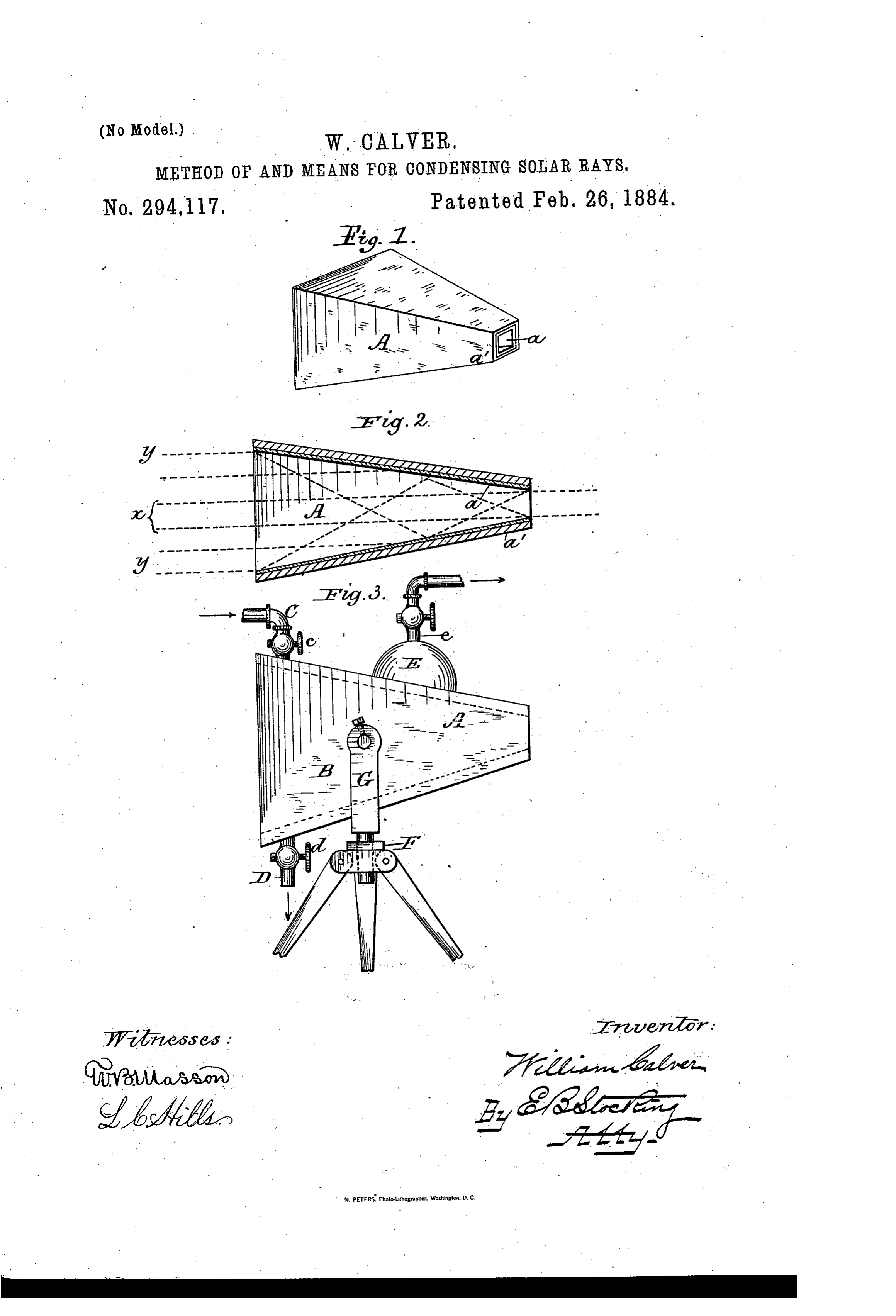
To all, whom it may concern: lected, predetermined, separated, or inde Be it known that I, WILLIAM CALVER, a pendent collection of the solar rays-as, for citizen of the United States, residing at Wash instance, a plane mirror presented to the sun ington,in the District of Columbia, haveinvent reflects nearly, all the rays falling thereon. 55 5 ed certain new and useful Means for Condens Such rays I consider collectively as a beam, ing Solar Rays, of which the following is a column, or body, and this designation apply Specification, reference being had therein to to said rays both before and after their reflec the accompanying drawings, in which tion. Heretofore in the art of utilizing solar Figure 1 is a perspective of a solar condenser rays all the rays of a column or beam have 6o IO Constructed in accordance with my invention been passed through or against a solid, and and adapted to practice my method of con practically all of said rays have been diverted densing Solar rays. Fig. 2 is a longitudinal from a straight line, so that not only has ob Vertical section of said condenser. Fig. 3 is a struction increased the loss of energy, but de side elevation of my condenser water-jacketed viation from a straight line of advancement 65 15 and mounted on a tripod. has added to the loss. In all reflectors a per Like figures.
letters refer to like parts in all the centage, more or less great, of loss is from ab Sorption, and deviation from a straightline, as
This invention is intended, primarily, to be by reflection or refraction, seems to be a po used in connection with solar reflectors or tent agent of such absorption; therefore, to ob- 7o heaters of any character, but preferably with tain the greatest energy of a beam or column, such as are shown in my patent of July 4, 1882, obstruction and deviation must be reduced to . although said condenser is also capable of the minimum.
practical use independent of any other appa I have devised several forms of condensel's ratus, as Will hereinafter appear. which are adapted to practice my method, and 75 25 Beretofore all methods of condensing solar have herein described one form which, as rays, either of heat, light, or any other spe shown in Fig. 1 at A, is in outline a frustum cific character, involved the passage thereof of a pyramid, the inclination of the sides of through or against a solid substance as a lens which relative to its axis is limited by one re Or a reflector. . In these methods an actual loss quisite only--that is, to such an angle that no 8o of energy, whether heat, light, or chemical, material portion of the beam of rays entering has been sustained by reason of the interposi at the base shall be reflected backward. The tion of said solid substance. This loss may material and mechanical proportions and con have been caused by impeding the advance struction of my condenser may be varied to ment of the rays or by absorption thereof by suit the specific character of the rays of the 85 35 the Solid substance through or against which Sun to be condensed, whether of heat, light, they have been made to pass, or from other actinic, or other rays thereof. In this in CauSeS known or unknown I have discov stance I illustrate a condenser adapted to op ered a method whereby solar rays may be con erate upon the heat-rays primarily, but also densed without practical loss of heat, or, in adapted for use in connection with the light go other words, with a manifest clear gain of heat and other rays, and either in connection with Over that produced from an equal column, or independently of suitable reflectors. The beam, or body of rays condensed by the old inner surfaces, a. are constructed of glass, or methods so far as applied to the art of con it may be any suitable reflecting material, and trolling Solar heat, and in quantity or degree the outer surface, a, is in this instance of 95 rendering it available for practical purposes. wood, to serve as a backing and protection to Heretofore scientific experiments with artifi the glass. If desired, the outline may be that cial heat have been practiced, wherein the of a frustum of a cone, or may be composed of rays have been condensed with a gilded paper numerous plane surfaces or sides, instead of Cone to demonstrate that said rays were sub four, as shown. IOO . 5Oject to the same laws as those of light. By a The operation of the condenser is as follows: “beam, column, or body of rays’ Imean ase A beam or column, y a y, of solar rays being
Page 3
received or directed into the condenser in the heated air or the steam emerging from the direction indicated by the arrows, the central jacket at the same time that the main beam Ol' rays, ac, of the beam or column proceed in column of rays is being applied to practical straightlines and unobstructed, while the outer purposes; but as these are within the province rays, yy, are directed by the flaring walls of of mechanical skill they are not herein shown. the condense into or toward the central rays, Having described my invention and its op and thus the heat or other energy thereof is eration, what I claim is confined, condensed, increased, or accumulated 1. A condenser for Solar rays, comprising a in the reduced beam emerging from the con frustum of a pyramid, or its described equiva IO denser. i lent, the length of the same and the inclination It will be noticed that the extreme outer lays of its walls with its axis being relatively de of the column or beam are twice areflected with termined to advance the rays entering at its in the condenser ere they emerge, and I find by base, and to deliver them from its apex in a practice that this is a satisfactory limit to the smaller column or beam, the whole constructed number of reflections which may occur by so as to withstand high degrees of heat, Sub 55 reason of the length and relative inclination of stantially as Specified.
the walls of the condenser; but I do not limit 2. A solar condense comprising a hollow myself to any specific proportionate length, or frustum and a surrounding water-Space pro any specific number of reflections resulting vided with an inlet, an outlet, and a steam therefrom. outlet, each provided with controlling-valves, AS before stated, each reflection adds to the substantially as specified.
absorption of the heat-rays or the conversion 3. A Solar condenser comprising a frustium of light into heat, and I therefore illustrate of a pyramid, or its described equivalent, hav in Fig. 3 a condense provided with a water ing inner reflecting walls or surfaces, a, and an 25 jacket, B, having an inlet, C, and outlet l), outer re-enforcing and protecting backing, (t", provided with controlling-valves cd, respect Substantially as shown.
ively, so that a continual stream of Water (or, 4. The combination of the condenser A, if desired, air) may be kept in circulation about swivel-bracket G, and tripod F, substantially the condenser, and thus cool the walls thereof as shown and described.
and prevent undue absorption of heat; or by 5. The combination of the condenser A, retaining a body of water about the condenser jacket B, steam-dome E, inlet C, and outlets it may be converted into steam, be collected De, substantially as shown and described. and stored in the steam-domeE, and conducted In testimony whereofI affix my signature i through the pipe e for application to practical presence of two witnesses.
To render the condenser and jacket porta WILLIAMI CALVER. ble and adjustable for varied presentation to the sun or to reflectors, Imount the same upon Witnesses:
a tripod, F, and swivel-bracket G. Suitable E. B. STOCKING, accessories may be provided for the use of the N. P. CALTAN.
Provenance
- Collection
- Cited prior art
- Original PDF
- patentimages.storage.googleapis.com →
- Pages
- 3
- Method
- pdftotext (the PDF's own text layer) + pdftoppm 300dpi page scans
- Source
- Google Patents bibliographic record
- Granted
- 1884-02-26
- Transcribed from
- patentimages.storage.googleapis.com →