patent · US2914041
High compression spark ignited gas engine and method
24 November 1959
Page 1
Drawing sheet — no readable text.
Page 2
United States Patent Office 2,914,041 Patented Nov. 24, 1959
- Considering the invention broadly for the moment, the use of high compression ratios in gas engines is highly c 2,914,041 desirable, for example 10, 11 and 12 to 1. However,
HIGH coMPRESSION SPARK IGNITED GAs 5 atignition becomes faulty at the lower load, for example, no load to half load, and possibly above, because
ENGINE AND METHOD
Kurt Froehlich, Milwaukee, Wis, assignor to Nordberg the mixture in the cylinder is too lean. Throttling of Manufacturing Company, Milwaukee, Wis., a corpo the air inlet line to the engine is not desirable because ration of Wisconsin it involves pumping losses. The range of fuel-air ratios
within which an electric spark will ignite a fuel air mix
Application June 20, 1956, Serial No. 592,622 10 accurately ture is quite limited; a highly complicated mechanism for controlling the air and fuel supply to maintain 4 Claims. (Cl. 123-1) . the resulting mixture in the cylinder within this limited range is far too expensive and undesirable.
I provide a simplified method of obtaining, at the
My invention is in the field of internal combustion 15 engines and is a high compression gas engine and also air-fuel loads, lighter a well localized mixture with the proper is a method of operating a high compression gas engine is simple. All ofignition.ratio for the fuel
The procedure and apparatus flows through the auxiliary
A primary object of my invention is a method of oper chamber 24, and through the passage or throat 26 into the cylinder. The combustion ating a high compression gas engine to insure ignition at duced. During the piston's compression
air is separately intro stroke, air will all loads, particularly the light loads. -- - - be forced through the throat 26 into the auxiliary cham - Another object is a gas engine with an auxiliary com ber so that around top dead center when the spark plug bustion mitted.
chamber through which all of the fuel- is adr
is energized, the mixture in the precombustion chamber
Another object is a high compression gas engine with 25 lighterbeloads will within the critical range of ignition. At the the mixture in the precombustion chamber an auxiliary chamber of the above type with means for will be ignitable, and it will serve as a high flame energy maintaining a combustible mixture in it at all loads.
Another object is a high compression gas engine with trigger In for the too lean mixture in the main chamber.
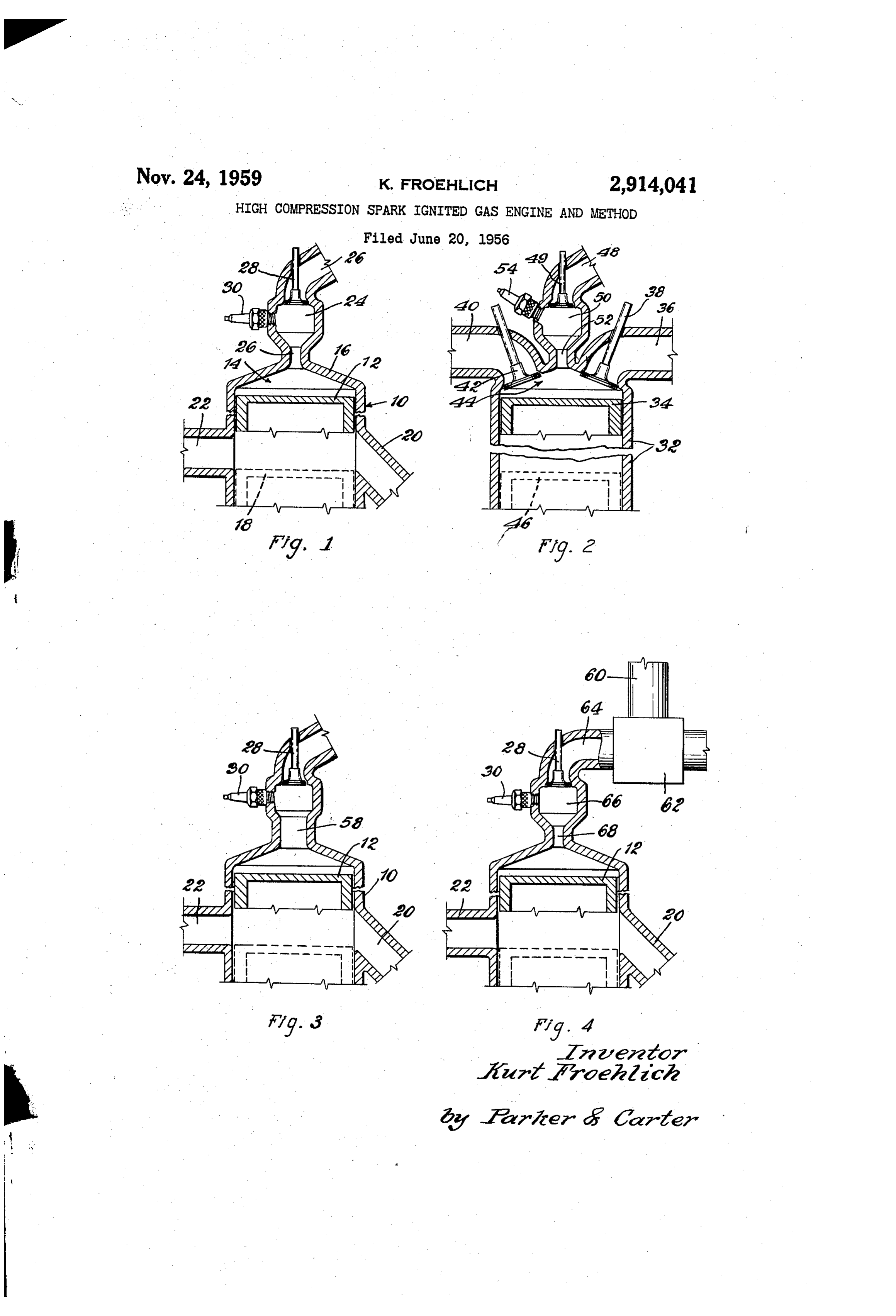
Figure 2 I have shown schematically a four-cycle means for insuring proper ignition at all loads. engine which has the usual cylinder 32 and piston 34, Another object is a simplified method of operating a 30 high compression gas engine so as to insure ignition at an inlet port or passage 36 controlled by the usual inlet valve 38, and an exhaust port 40 controlled by an ex the lighter load. ". . . haust valve 42. The piston at top dead center, shown . Another object is a method of operating a high com in full lines, defines the main combustion chamber 44 pression gas engine to maintain a lean mixture in the 35 with the cylinder head, and bottom dead center is indi cylinders at all loads for better efficiency. cated generally at 46 in broken lines. Other objects will appear from time to time in the en Gas is supplied through a conventional line 48 and suing specification and drawings in which: , valve 49 to an auxiliary combustion or precombustion Figure 1 is a vertical section of one form of my inven chamber 50 which communicates with the main combus 40 tion chamber through a throat or reduced passage 52, a tion; ..., ... . . . . . . . .
Figure 2 is a vertical section of a variant form; conventional spark plug 54 or the like being provided Figure. 3 is a vertical section of another variant; and for the chamber.
Figure 4 is a vertical section of still another variant. The principle is substantially the same as Figure 1. In Figure 1 I have indicated an engine cylinder gen The timing of the inlet and exhaust valve may be con erally at 10 with the usual piston 12. In the upper full 45 ventional. The gas valve, which admits all of the gas line position, the piston defines what I shall term a main for the engine to the auxiliary combustion chamber, may combustion chamber 14, with the cylinder head 16. In be timed relative to the inlet and exhaust valve timing its lower or dotted line position: 18, which may be con and also relative to the engine speed. But in any event sidered bottom dead center, the piston uncovers inlet the resulting mixture in the precombustion chamber 50 ports at 20, for the admission of fresh air for combus 50 has an air-fuel ratio within the critical range due to tion and exhaust ports at 22, for the exodus of the spent air being forced back through the throat 52 by the piston or burnt products of combustion. So far the engine will during its compression stroke. All of the gas is admitted be recognized as a conventional two-cycle engine. to the precombustion chamber first, and more or less may An auxiliary or precombustion chamber 24 communi flow into the main combustion chamber, depending upon cates at a suitable point through the cylinder head by a 55 the load and the quantity of gas being supplied. All of throat or passage 26 with the main combustion chamber. the combustion air is admitted through the inlet port 36 The passage or throat is reduced in cross-section and is and the burnt products of combustion leave by the much smaller in diameter than the auxiliary chamber. port 40.
Gaseous fuel is brought in through a suitable pipe 26, or Normally all of the gas is admitted before compression the like, from a suitable gas source and enters the auxil 60 starts. In two-cycle engines part of the gas may be ad iary chamber under the control of a suitable valve 28 mitted during the early part of the compression stroke, which is opened and closed by any conventional mech with the result that the mixture in the auxiliary chamber anism. Ignition may be obtained by a suitable spark becomes richer. In all probability it can be held within plug 30 or the like in the auxiliary chamber. the high limit of inflammability. Several of the important points are as follows. All 65 In those cases where it cannot be held within the the gaseous fuel supplied to the cylinder is first admitted critical range, the throat between the main and auxiliary to the auxiliary chamber and must pass through the throat combustion chambers may be increased in size so that 26 into the main combustion chamber. Only air is more air may be forced from the cylinder to the pre admitted through the ports 20 in the cylinder wall and combustion chamber during the compression stroke to it should be understood that the inlet and exhaust ports 70 dilute the gas. In Figure 3, I have shown a two-cycle. 20 and 22 around the cylinder wall can be arranged in any engine substantially the same as Figure 1 except that the Suitable matically.manner and I have only shown them diagram throat 58 is substantially larger than throat 26 in Figure 1. This allows more air admitted through the inlet line
Page 3
or ports 20 to flow back under piston compression into automatically make the mixture richer in the precom the precombustion chamber to dilute the mixture to pre bustion chamber. vent it from being too rich. While I have shown and described a preferred form Another way of diluting the mixture in the precombus and several modifications of my invention, it should be tion chamber in a two-cycle engine where gas is admitted understood that numerous additional modifications, sub during the early part of the compression stroke is shown stitutions, alterations and changes can be made without in Figure 4 where a suitable air source 60 is connected departing from the invention's fundamental theme. I to a mixer or blender 62 to dilute the incoming gas in therefore wish that the invention be unrestricted except the inlet line 64 leading to the precombustion chamber 66, 0 as by the appended claims.
and the throat 68 may be the same size as the throat in I claim: . . . . - - Figures 1 and 2. In this case air could be admitted to sion1. Ainternal method of operating a gas fueled high compres combustion engine over a selected load dilute the gas coming into the precombustion chamber, depending upon the load and operating conditions. range, the engine having a main combustion chamber An important point is that, by admitting all of the gas defined by the cylinder and piston at top dead center, to the precombustion chamber first and creating a com 15 and an auxiliary combustion chamber communicating bustible mixture in it, the mixture in the main chamber with the main combustion chamber by a reduced cross or cylinder at all loads must be lean, in fact too lean for section passage; including the steps of supplying all of combustion without the trigger of the precombustion. the gas fuel in an incombustible state at all loads directly chamber. This gives better efficiency and better fuel 20 to the auxiliary combustion chamber in varying quan economy. - - -- - -- - - - - - tities depending upon the load and relative to the volume
The use, operation and function of my invention are of the auxiliary combustion chamber such that at the as follows: higher loads a portion of the gas fuel in the auxiliary I. provide a precombustion chamber for either two or chamber will flow through the reduced cross section, four-cycle engines which receives all of the gas being 25 passage into the main combustion chamber and at the supplied to the engine. The chamber communicates with lower loads substantially all of the gas fuel will be con the main combustion chamber below the cylinder head fined to and will remain in the auxiliary combustion. by a throat or reduced cross section passage. A suitable chamber, separately supplying, at all loads, only combus ignition device, i.e. a sparkplug, may be positioned in the tion air directly to the cylinder at least at a pressure as precombustion chamber and energized at an appropriate 30 great as atmospheric, timing the admittance of both the time to ignite the mixture. - . . . . . .' gas fuel to the auxiliary combustion chamber and con All of the air for combustion purposes is separately bustion air to the cylinder such that gas fuel will be admitted directly to the cylinder. During piston com admitted to the auxiliary combustion chamber no earlier pression some of the air from the cylinder is forced than the beginning of air admittance to the cylinder, and through the throat by the piston to dilute the gas in the compressing the thus admitted air in the cylinder with precombustion chamber to form a combustible mixture 35 the piston through a ratio that will force a sufficient therein. This is true at both the high and the low loads. amount of the combustion air from the main combustion At the lighter loads in a high compression gas engine chamber through the reduced cross section passage into where the inlet is not throttled, the mixture in the cylin the auxiliary combustion chamber which, when mixed der will be too lean for ignition by a spark. By admitting 40 with the quantity of gas fuel in the auxiliary combustion all of the gas through the precombustion chamber and chamber, will form a 'combustible mixture therein at all all of the air directly to the cylinder, air is forced back loads.
into the precombustion chamber during the piston's com 2. The method of claim 1 in which the engine is a pression stroke to provide an enriched mixture within the four-cycle engine, and further characterized by the step limits of inflammability. of supplying all of and only gas fuel directly to the
The invention can be used with various types of gases, 45 auxiliary combustion chamber before all of the combus for example methane, propane, natural gas, coke oven tion air, has been supplied to the cylinder. .. . gas, producer gas and the like. 3. The method of claim 1 in which the engine is a The engine should be designed with a high compres two-cycle engine, and further characterized by the step sion ratio, for example 11 to 1, which is a conventional 50 of timing the admission of the gas fuel so that part of diesel compression ratio. The volume of the precombus it is admitted during at least the initial part of the com tion chamber, the cross-sectional area of the throat, and pression stroke.
the compression ratio must all be related to each other 4. The method of claim 3 further characterized by and in design to acquire a combustible mixture in the auxiliary including the step of admitting a quantity of bleed air chamber at the light loads. Additionally, the particular directly to the auxiliary combustion chamber to some type of gas being used, be it a low or a high B.t.u."gas, 55 what dilute the mixture therein without reducing it to a must also be considered. combustible ratio so that, when combustion air is forced In two-cycle engines where part of the gas may be through the reduced cross section passage into the auxil admitted during the early part of the piston's compression
Srtoke, the throat should either be opened up, as in Fig 60 iary chamber, a combustible mixture will result in the auxiliary combustion chamber.
ure 3, or air should be bled into the gas line, as in Figure 4, to lean down the mixture in the precombustion cham ber. Cr a combination of these two could be used.
References Cited in the file of this patent
UNITED STATES PATENTS
In the case of a low B.t.u. gas, for example pro ducer gas, where a high compression ratio is being used, 1,271,942 Ricardo ------------...-- July 9, 1918 it might be desirable to admit part of the gas during the 65 1,354,786 Tartrais ----- ----------- Oct. 5, 1920 compression stroke to make the mixture in the auxiliary 1,649,700 Jobes ----------------- Nov. 15, 1927 chamber richer. On the other hand, the compression 2,065,419 Bagnulo --------------- Dec. 22, 1936 ratio for such a gas in all probability will be lower than 2,314,175 Summers -------------- Mar. 16, 1943 for other gases, and the lower compression ratio will 2,511,405 Hoover ---------------- June 13, 1950
Provenance
- Collection
- Cited prior art
- Original PDF
- patentimages.storage.googleapis.com →
- Filed
- 1956-06-20
- Pages
- 3
- Method
- pdftotext (the PDF's own text layer) + pdftoppm 300dpi page scans
- Source
- Google Patents bibliographic record
- Granted
- 1959-11-24
- Inventors
- Froehlich Kurt; Nordberg Manufacturing Co
- Transcribed from
- patentimages.storage.googleapis.com →