patent · US2880616
Compensated gyroscope
7 April 1959
Page 1
Drawing sheet — no readable text.
Page 2
Drawing sheet — no readable text.
Page 3
Drawing sheet — no readable text.
Page 4
United States Patent Office 1.
Patented Apr. 7, 1959
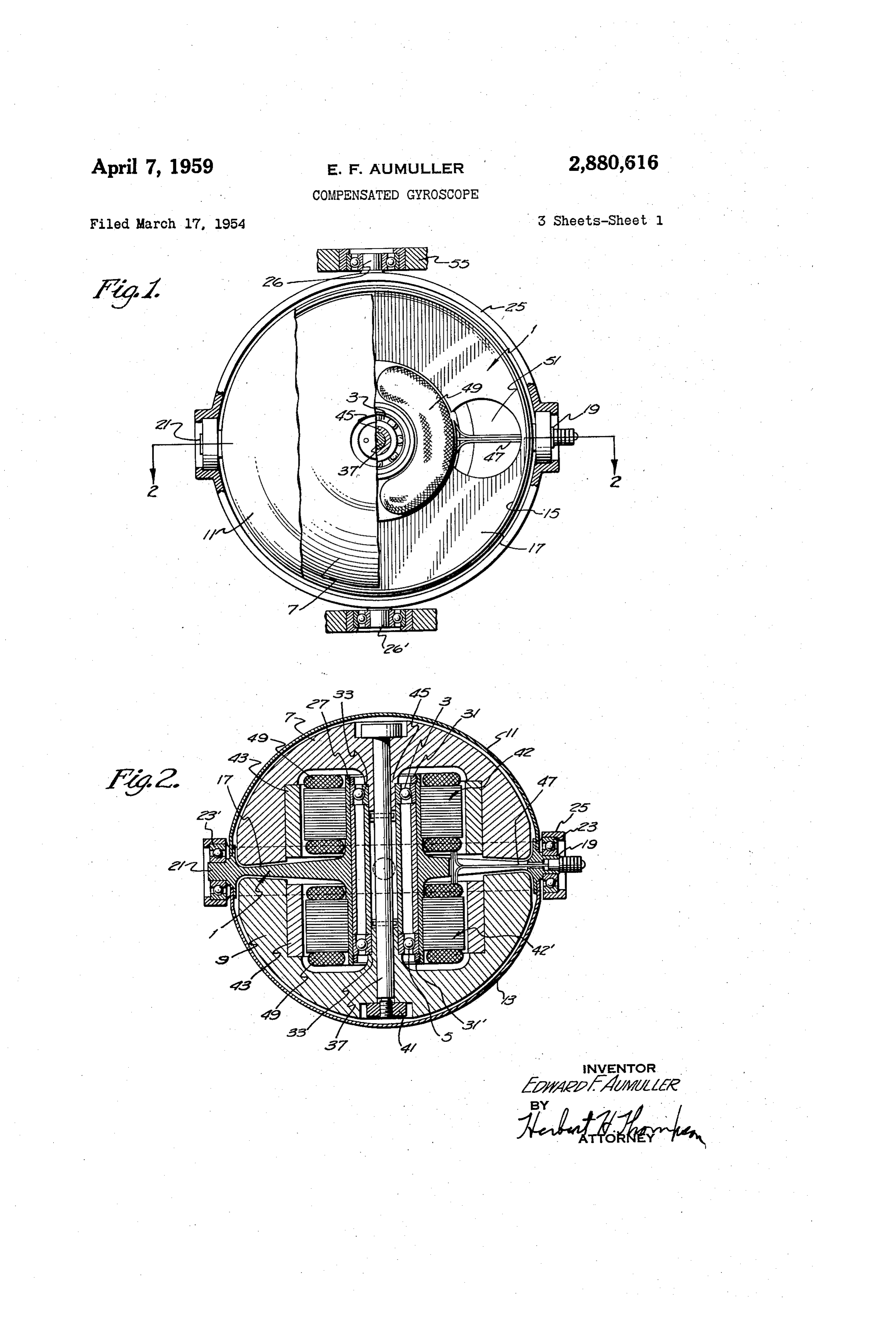
their enclosing casing or shells 11 and 13, as is the usual practice. The shells 11 and 13 constitute correspondingly shaped members for enclosing the rotors that are fitted in 2,880,616 oppositely disposed relation on the circumferential rim portion of the frame 1. Said bearing frame is shown as
COMPENSATED GYROSCOPE comprising a circumferential ring 15 or wheel having a Edward F. Aumuller, Lynbrook, N.Y., assignor to Sperry acentral part web or disc 17 and trunnions 19 and 21 forming of the bearings 23-23' between the gyroscope and
Rand Corporation, a corporation of Delaware the gimbal ring 25. The central web is provided with a Application March 17, 1954, Serial No. 416,853 0 hub or axially extending tube-like projections 27 which 6 Claims. (C. 74-5.7) extend in both directions from the web and and within which are mounted the aforesaid rotor bearings 3 and 5.
The gimbal ring 25 in turn is journalled on trunnions 26, 26' within a fixed support 55. If the gyro happened
This invention relates to an improved construction for 5 to be designed as having but a single degree of freedom gyroscopes, and especially for the rotor bearing frames in addition to the spin axis, it will be understood that the gimbal ring 25 will be omitted and the bearings 23-23' and the rotors thereof. In the usual construction, the will be located directly in the fixed support. outer case which encloses the rotor also provides the spaced bearings in which the rotor shaft is journalled. 20 typePreferably, the rotor bearings are of the ball bearing with the outer races held within the two ends of the
It is, therefore, necessary to make the casing of sufficiently hub against spacing sleeve 29 by locknuts 31-31. The heavy and rigid material to keep the rotor bearings in their proper spaced position and in alignment. Much inner races 33 are spaced by a second sleeve 35 through trouble has also been experienced in prior designs by which extends a central tie rod or shaft 37 on each end to which the hubs 45 of each of dual rotors 7 and 9 are unequal expansion of the rotor and its shaft with respect 25 secured. Said rod closely fits the hubs 45 but is preferably to the enclosing casing, causing binding and unbalance of less diameter than the interior of the sleeve 35, and about one or more axes of the gyroscope.
According to my invention, I use the outer casing only when the device is assembled, the rod is locked to each as an enclosure for the rotor but support the rotor bear hub by the engagement of cross pins 39 in the forked end ings from a web extending through the middle of a 30 of each hub. After assembling, the nut 41 is screwed divided or split rotor constituting dual rotors. Such web onto the lower end of the shaft 37 and tightened, as shown also supports on opposite sides thereof a common stator inmake Fig. 2, preferably placing the shaft 37 under tension to a rigid rotor shaft and to lessen thermal expansion.
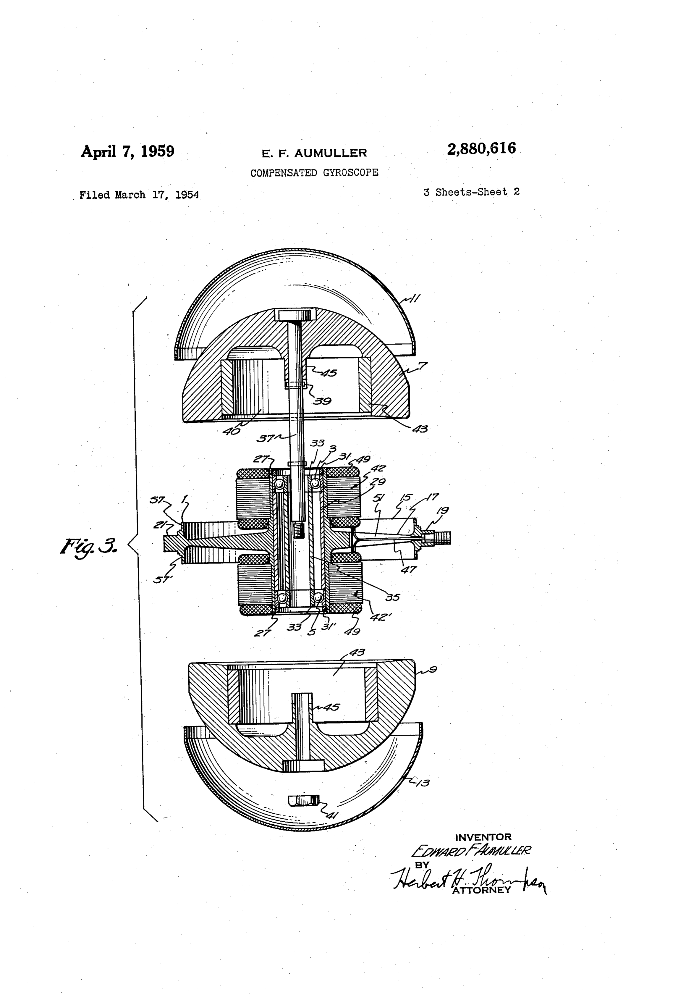
or two like stators for the two rotors. The rotors are Each rotor journalled within sleeves or hubs extending in both di exteriorly and is preferably of generally hemispherical shape rections from the web and lying within and supporting the 35 facing cavity 40eachwithis hollowed out interiorly to form the interior perimeter of each stators, and are tied together by an axially extending cavity mounting the squirrel cage construction 43 of the strut, preferably placed under tension, thus forming a polyphase induction motor which spins each rotor. The common shaft for the rotors. The two rotors and their two stators 42 and 42' are shown as mounted on the two stators are entirely symmetrical on both sides of the web so that no disturbance of the gyro balance will be caused ends lead of the hub or sleeve 27 on each side of the web 17. due to thermal expansion. Furthermore, in my design, 40 The in wires 47 to the windings 49 of the stators are shown as passing through a central aperture in one the heat from the stators is effectively dissipated to the of the trunnions 19, the web being provided with a cut exterior of the case which is connected to the web so as to conduct the heat from the same to the two exterior away portion 51 to give access to the wires. The entire dual rotor is enclosed in a thin shell of sheet shells or cups. Since the shells do not support any bear 45 material, ings, they may be made very thin and light, and are pref such as steel, formed in two sections or cups 11 and 13. Each section tightly fits and is adapted to be erably of hemispherical shape so as to be readily re hermetically movable and also easily hermetically sealed to the cir sealed to the upper and lower flanges 57-57" cumferential flanges forming the rim on the web or wheel. formed in the rim or ring 15, and it will be observed that The case may, therefore, be either evacuated or floated in 50 these shells or cups do not support any bearings nor have any wires passing therethrough so that the shells may be a liquid, or both. readily removed for inspection of the rotors and the Referring to the drawings illustrating two forms my in vention may assume, spinning motors.
Fig. 1 is a plan or elevational view of a gyro con thatA itstudy of the construction above described will show possesses many advantages over the standard con structed in accordance with my invention with the gimbal, 55 struction of gyro rotors now employed and constitutes a one casing, and also one rotor partly cut away to show high precision temperature compensated gyroscope of a the interior construction. If Fig. 1 represents a gyro of the directional type it is an elevation, while if it represents simple, rugged construction and with completely sym metrical design. Thus, the rotor bearing frame 17 and a gyro vertical it is a plan view; its hub 27 may be made in one piece so that the rotor Fig. 2 is a transverse section taken on line 2-2 of 60 bearings are maintained in the original alignment at all
Fig. 3 is an exploded sectional view showing the dual times. The unbalancing effect of expansion of the parts rotors and their enclosing cups and the central interior due event to thermal expansion is largely prevented and in any completely compensated by the fact that twin rotors bearing frame which supports the two stators, and on and twin stators are employed on each side of the gyro which the rotors are journalled; 65 axis assuring equal expansion on both sides of the trun
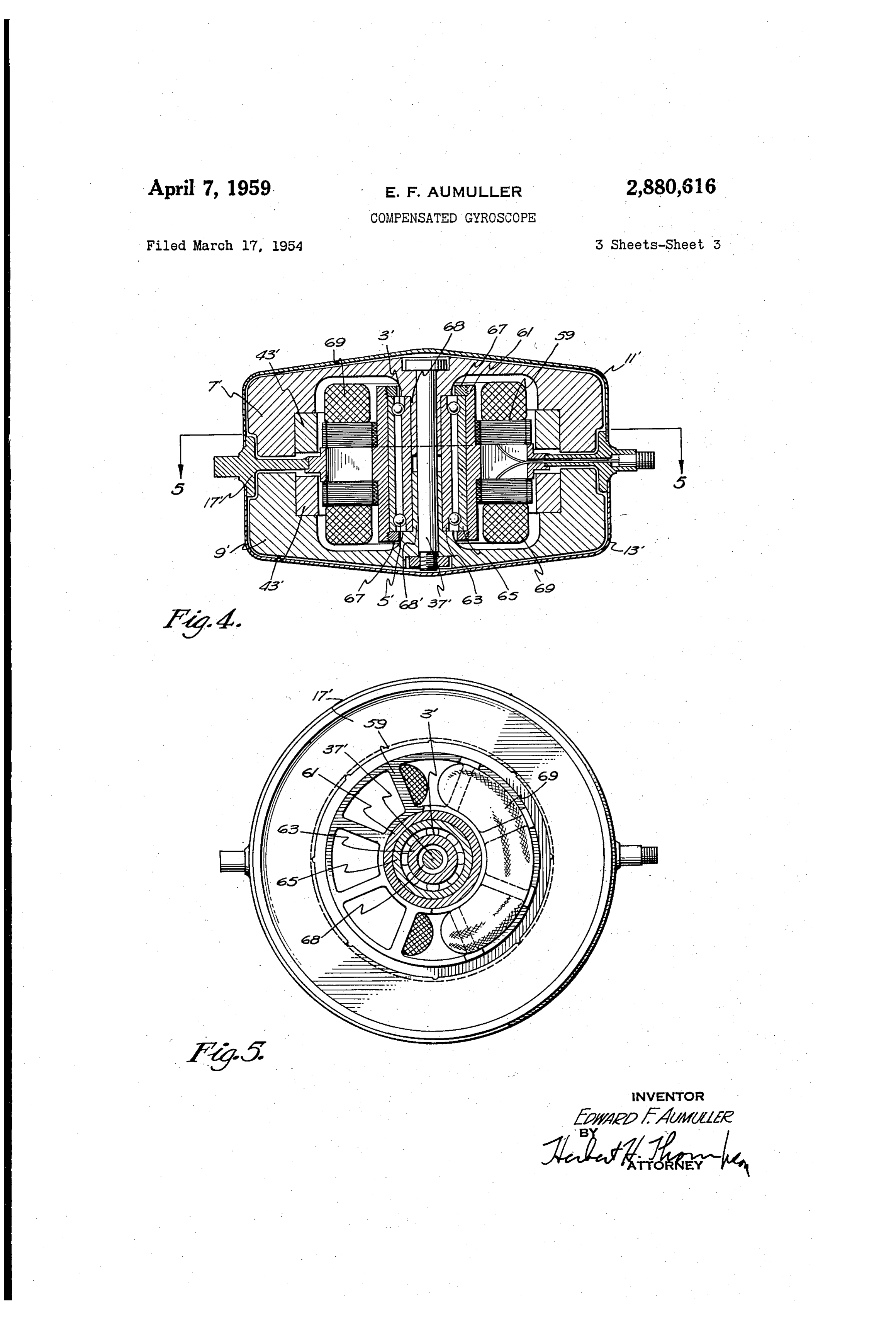
Fig. 4 is a sectional view similar to Fig. 2 showing a nion axis 19, 21. This permits the employment of a modified form of the invention; and different metal in the rotor structure than in the casing Fig. 5 is a transverse section taken on broken line 5-5 or rotor frame thus permitting a very heavy metal to of Fig. 4.
From Fig. 3, it will be at once apparent that my main 70 be employed in the rotors without disturbing the balance of the gyroscope due to temperature changes.
frame 1 which supports the rotor bearings 3-5 lies within instead of without the rotor or rotors 7 and 9 and In my construction also, the heat generated in the
Page 5
stator windings is readily dissipated to the exterior ring 15 bearings, an electrical stator supported on said hub, a and shells by the solid web or disc 17 which extends be cup-like rotor normally overlying said stator and having tween and beyond the two rotors where it is joined to a shaft normally projecting through said sleeve, means for the outer shells. My construction also may be readily securing said rotor and shaft to said sleeve, and an outer disassembled for inspection without disturbing the rotor 5 cup-like case secured to said rim around its periphery, bearings or wiring. whereby said case may be removed without disturbing A somewhat modified form of my invention is shown the rotor bearings or stator.
in Fig. 4. According to this modification, the twin rotor 3. A gyroscope as claimed in claim 2, wherein said construction and an interior rotor bearing frame 17' are rotor shaft detachably clamps said rotor to said sleeve, retained, but the twin rotors 7 and 9' and shells or cups O whereby the rotor may also be removed without disturbing 1' and 3' are shown as bowl shaped instead of hemi the rotor bearings or stator.
spherical as in the previous form. In this form also, the 4. A gyroscope comprising closely positioned twin, central web 17 extends only partially between the rotors cupped rotors having facing cavities, a rotor bearing frame and a single stator frame 59 is employed, the exterior of resembling a disc wheel having an outer rim, a central which is rigidly secured within the web 7' around its web positioned between the rotors, each rotor having a inner periphery. In this form, the stator frame 59 pro hub extending within its cavity, means for tying said hubs vides the hub 61 which houses and supports the spaced together to form a common shaft for the rotors, spaced rotor bearings 3' and 5'. bearings for said shaft, means for supporting said bear A modified form of ball bearing is also shown in Figs. 4 ings by said central web, and a pair of end cups of sheet and 5. Such bearings may have common inner and 20 material adapted to enclose the rotors and to closely fit common outer races in the form of long sleeves 63 and the rim of said disc wheel.
65 near each end of which the ball races are formed and 5. A gyroscope comprising closely positioned twin, balls mounted. The outer sleeve 65 is shown as held in cupped rotors having facing cavities and a rotor bearing place within the hub by locknuts 67, while the inner sleeve forms a spacer between the two inner hubs 68 and 25 including a centrala web frame resembling wheel having an outer rim, said frame positioned between the rotors and 68 of the two rotors. While each rotor has its own a hollow hub extending within each cavity, said rotors Squirrel cage 43', the stator may be common to both and also having hollow interior hubs extending toward each have common windings 69. The two rotors may again other and spaced bearings journalling said hubs within the be tied together by a central tie rod 37 as before. This hub of said frame, and a pair of end cups construction possesses substantially all the advantages of 30 adapted to enclose the rotors and to fitofthesheetrim material of said the construction of Figs. 1 to 3. wheel.
Since many changes could be made in the above con 6. A gyroscope comprising a rotor bearing frame re struction and many apparently widely different embodi sembling a wheel having a circumferential rim portion, ments of this invention could be made without departing a central web portion and a hub portion, a pair of coaxial from the Scope thereof, it is intended that all matter con 35 rotors tained in the above description or shown in the accom the websupported portion in on the hub portion of said frame with equidistant and central relation thereto, panying drawings shall be interpreted as illustrative and and a casing for enclosing the spaced rotors formed of a not in a limiting sense. pair of correspondingly shaped members fitted in op What is claimed is:
1. A gyroscope comprising closely positioned twin, 40 positely disposed tion of said frame.
relation on the circumferential rim por hemispherical rotors, each having facing cavities, a rotor bearing frame resembling a wheel having a central web References Cited in the file of this patent positioned between the rotors, a hub extending within both cavities, each rotor having a hollow interior hub UNITED STATES PATENTS journalled within the hub of said frame, said web termi 45 2,345,915 Carlson ----------------- Apr. 4, 1944 nating at its periphery in a circumferential rin, journals 2,382,967 Beach ----------------- Aug. 21, 1945 on said rim for pivotally supporting said gyroscope, and 2,731,836 Wendt ----------------- Jan. 24, 1956 a pair of Substantially hemispherical sheet metal cups adapted to be secured to each side of said rim. FOREIGN PATENTS 2. A gyroscope comprising a circular plate having a 50 2,695 Great Britain ----------- July 19, 1906 rim, a central hub projecting on at least one side thereof, of 1906 a sleeve journalled within said hub on spaced antifriction 623,943 Great Britain ----------- May 25, 1949
Provenance
- Collection
- Cited prior art
- Original PDF
- patentimages.storage.googleapis.com →
- Pages
- 5
- Method
- pdftotext (the PDF's own text layer) + pdftoppm 300dpi page scans
- Source
- Google Patents bibliographic record
- Granted
- 1959-04-07
- Transcribed from
- patentimages.storage.googleapis.com →