patent · US2554263
Gasification of carbonaceous solids
22 May 1951
Page 1
Drawing sheet — no readable text.
Page 2
Drawing sheet — no readable text.
Page 3
May 22, 1951 K. J. NELSON 2,554,263
GASIFICATION OF CARBONACEOUS SOLIDS -
Filed Dec. 18, 1946. 3. Sheet:-Sheet 3
Flu (DZED
WATE 2 NLET
Karl U. . e. So in Sinventor es (24-4- atterses
Page 4
Patented May 22, 1951
UNITED STATES PATENT OFFICE
GASIFICATION OF CARBONACEOUS SOLIDS
Karl J. Nelson, Cranford, N.J., assignor to Stand ard Oil Development Company, a corporation of Delaware
Application December 18, 1946, Serial No. 717,064
The present invention relates to the conversion tial combustion of the carbonaceous charge with of carbonaceous solids such as all types of coal, in the fluid generator bed at high-carbon con lignite, peat, oil shale, tar sands, coke, oil coke, centrations, a gasification residue of the same cellulosic materials, including lignin, etc. into high carbon concentration is withdrawn from the gases containing carbon monoxide Stich as Water gas generator in continuous operation. This gas, producer gas and the like. high-carbon residue must be reprocessed in order Prior to the present invention, it has been to avoid carbon losses in the system. Gasifica suggested to gasify carbonaceous solids with a tion to low carbon concentrations at Substantial gasifying medium such as steam and/or air to ly constant conditions would require an excessive produce water or producer gas, in the form of a 0. ly large reaction Space without completely avoid dense turbulent bed of finely divided solids hav ing the carbon losses in the form of carbonaceous ing a particle size of about 4 to 2 in down to gasification residue.
about 400 mesh, fluidized by an upwardly flowing Generation of heat by combustion of high gas and maintained at gasification temperatures carbon gasification residue in a conventional ex of about 1500°-2500°F. This technique is greatly 5 ternal burner and heat Supply to the generator in superior to conventional fixed-bed operation. It the form of Sensible heat of combustion gases provides larger solid reaction surfaces, better So produced require excessive amounts of heating mixing and greatly improved temperature con gases in view of the high gasification tempera trol, and it affords higher gas yields in fully-con tures to be maintained in the gas generator and tinuous operation within shorter reaction times. 20 the temperature limitations imposed by the rela While these great advantages make the appli tively low heat resistance of economical con cation of the fluid solids technique to coal gasifi Struction materials for conventional burners. cation appear highly attractive it has not as yet It has also been suggested to generate heat by found the broad commercial application it-Would the combustion of solid carbonaceous gasification seem to deserve. One of the more important rea 25 residue in an external heater and to supply heat Sons of the slowness of this development lies in to the gas generator in the form of sensible heat difficulties encountered in the substantially com of solid combustion residue circulated from the plete conversion of the carbon feed with the car heater to the gas generator. Efficient combus bonaceous charge into product gas-and-heat re tion at high temperatures in an external heater quired for the process at reasonably, constant-con 30 of this type requires low carbon concentrations version conditions, satisfactory Steam conversion to avoid excessive air requirements and/or car rates, reasonable temperature levels and economic bon losses in the form of CO formed by the re equipment design. duction of CO2 with excess carbon. Fhis re Such substantially complete utilization of the guirement is incompatible with a high carbon carbonaceous charge is an essential condition for 35 ..concentration in the gas generator. the economic operation of the coal gasification It Will be appreciated from the above that the process. On the other hand, the rate of conver reconciliation of high carbon concentrations in a Sion of the gasifying medium in the Water gas "fluid' gas generator with a complete conversion as well as in the producer gas reaction decreases of the available carbon into gas and heatrequired rapidly as the carbon concentration in the con 40 for the process presents an important and diffi version Zone decreases so that relatively high cult problem. The present invention is concerned carbon concentrations are necessary for the pro With means for solving this problem. duction of satisfactory gas yields at a given tem It is, therefore, an important object of this perature per unit of time and reactor Space. invention to provide an improved process for pro
In conventional fluid solids: operation: the entire ducing combustible gases from carbonaceous solids reacting mass of fluidized carbonaceous solids hasemploying the fluid solids technique. a Substantially uniform carbon concentration. As Another object of my invention is to provide an a result, the requirements of complete carbon improved process for the gasification of carbona utilization and highest possible carbon concen Ceous Solids in the form of a dense, turbulent, tration can not be reconciled in an economical 50 fluidized bed of finely divided solids at optimum manner when conventional means of heat genera rates of conversion and with full utilization of tion are applied. - available carbon.
For example, when heat is generated by a par Another object of this invention is to provide
Page 5
improved means for supplying heat to a fluidized verted in the gas generator is utilized for heat bed of finely divided carbonaceous solids under generation rather than lost as it would be if the going gasification at optimum conversion rates by gasification were carried out at similar gasifica burning gasification residue in an external burner. tion conditions but without the use of my external A more specific object of my invention is to combustion Zone. An additional advantage of my provide improved means for supplying heat to a invention results from the fact that gas-gen fluidized bed of finely divided carbonaceous solids erating equipment for high-carbon, low-tempera undergoing gasification at optimum conversion ture operation is more economical with respect rates, full utilization of available carbon in the 0. to Size and cost of construction materials than equipment for low-carbon and/or high-tempera process and convenient disposal of ash.
Other and more specific objects and advan ture operation.
tages will appear hereinafter. The extremely high combustion temperatures In accordance With the present invention, finely required for the purposes of my invention may divided carbonaceous solids are subjected in a gas be produced, for example as has been recently generation Zone to a gasification reaction with a 5 shown, by passing a suspension of finely divided gasifying medium at gasification conditions of Carbonaceous Solids in a combustion-Supporting temperature and preSSure, in the form of a dense gas such as air and/or oxygen tangentially along the axis of a cylindrical combustion Zone thereby turbulent bed of finely divided solids of substan imparting tially uniform and high Carbon concentration a rotating motion to the Suspension, conducive to highest rates of conversion of the if desired, aided by a gas, preferably secondary gasifying medium used. Solid finely divided gasi combustion-supporting gas, introduced tangen fication residue having the average carbon con tially into the combustion zone at a high velocity Centration of the gasification bed is burned in a of about 200-800 ft. per second to bring the total separate combustion Zone at temperatures above oxygen Supply to about 105-600% of the theo the melting point of the ash of the carbonaceous 25 retical. However, it is only necessary to Supply charge, that is, about 2000-3500 F., preferably that amount of oxygen to the combustion Zone, 2700°-3300 F. and at an oxygen supply at least which is required to burn the carbon therein sufficient to permit complete combustion of the substantially completely while any excess oxygen carbon introduced into the combustion Zone. thereover may be by-passed and admitted directly Liquid ash may be withdrawn from the combus 30 to the gas generator. The secondary combustion tion Zone While flue gases are Supplied to the Supporting gas may amount to as much as about fluidized Solids bed Of the gasification Zone Sub 98% of the total combustion-Supporting gas sup stantially at the extremely high temperatures of plied to the combustion Zone. The combustion the COmbustion ZOne to Supply at least a portion ZOne may be either Substantially vertical or Sub Of the heat required by the gasification reaction. 35 stantially horizontal With a tilt downward toward LOW-carbon Solids carry-over from the combus the discharge end to facilitate the flow and tap tion ZOne to the gas generation Zone is substan ping of liquid ash. Instead of Secondary Com tially avoided by the fusion and liquid drawoff of bustion-Supporting gas steam, CO2, or the like the ash in the combustion Zone. may be used as the gas introduced tangentially Complete combustion of the carbon supplied 40 if the amount of primary combustion-Supporting as gasification residue to the combustion zone gas is high enough to Satisfy the requirements of normally requires a considerable excess of oxygen the proceSS.
to be supplied to the combustion zone. This ex In operation, a violent Swirling action takes cess oxygen enters the gas generator as a con place within the combustion Zone due mainly to Stituent of the high temperature flue gas so that the tangential velocity of the Secondary gas and the heat balance required for the conversion of to some extent to the rotary motion of the Solids carbon and gasifying medium into fuel gas is es in-gas Suspension fed axially. As a consequence tablished by the fast and extremely exothermic of centrifugal force, the internal walls of the reaction between oxygen and carbon, for example, combustion zone are covered with a film of molten in accordance With the following equations: 50 ash which travels in a spiral manner and eventu (1) C--O2->CO2--170,000 B. t. u. ally discharges at the lower end of the con (2) C--CO2->2CO-74,500 B. t. u. bustion zone. The larger carbonaceous par (3) CO--H2O->CO2-i-H2--18,100.B. t. u. ticles are caught in the slag film and burned by the combustion-supporting gas passing by at
Since reaction (1) is very fast, reaction (2) rela 55 higher velocity, while the Smaller particles burn tively slow and reaction (3) of intermediate speed in the gas Zone. The fines burn almost instan the desired gas composition may be established by taneously in the vortex to which a small volume adapting the contact time of solids and gases at of tertiary combustion-supporting gas, amount any given gasification conditions of temperature, pressure, carbon concentration, reactivity of the 60 ing to about 1-5% of the total combustion-Sup porting gas, may be fed to accelerate this com
Solid charge and steam to oxygen ratio to the requirements of either reaction (2) or reaction bustion.
(3) either of which requires contact times Sufi The combustion chamber may be a steel cyl ciently long to allow for the completion of reac inder lined with refractory such as chrome ore tion (1) and for optimum utilization of the heat 65 or
the like. Since the sintering or melting points even the most heat resistant refractory linings obtained from the latter. Adaptation of the con usually lie Substantially below the prevailing tact time to the requirements of the Slowest reac combustion temperatures, cooling tubes are pref tion (2) Will permit the formation of sufficient erably imbedded in the lining. CO2 to generate the heat required While permit The temperatures reached in a combustion ting a reduction of CO2 formed to establish the 70 Zone of this type when pure or concentrated desired minimum CO2 content of the final product oxygen is used as the combustion-Supporting gas gaS.
In this manner, the gasification reaction may are substantially higher than those required to be conducted at optimum carbon concentrations establish an efficient temperature differential be and conversion rates at relatively low conversion 75 tween the combustion zone and the gas genera tion Zone. In actual operation I prefer, there temperatures while all available carbon not con
Page 6
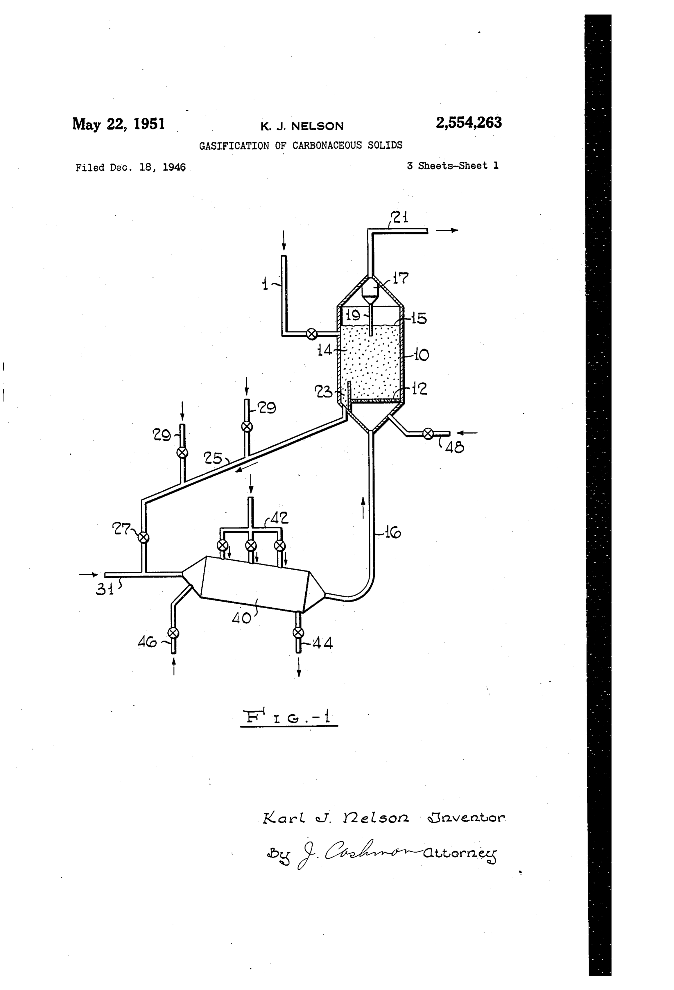
fore, to use air or oxygen diluted with steam or version rates. In this, as in the embodiment flue gases as the combustion-supporting gas the operating Without Solid heat carrier, the total proper choice of which depends on the type of available carbon is eventually converted into gasification reaction desired. When producer gas product gas and heat required for the process is to be manufactured in the gas generation Zone, 5 and the ash is effectively disposed of. air is a suitable diluted combustion Supporting Having Set forth its objects and general na gas while for the production of Water gas oxygen ture, the invention will be best understood from diluted with steam is preferred. the more detailed description hereinafter in As mentioned above, the external combustion which reference will be made to the accompany zone is normally operated With an excess of OXy O ing dra Wing wherein gen so that unconverted oxygen becomes avail figure 1 is a partly schematical partly dia able for conversion and/or heat generation within grammatical illustration of a system utilizing the gas generation zone. For the generation of the Sensible heat of high temperature fue gases producer gas this excess of oxygen may be chosen as a Scurce of heat for the gas generation re high enough to supply, in combination with the 5 action,
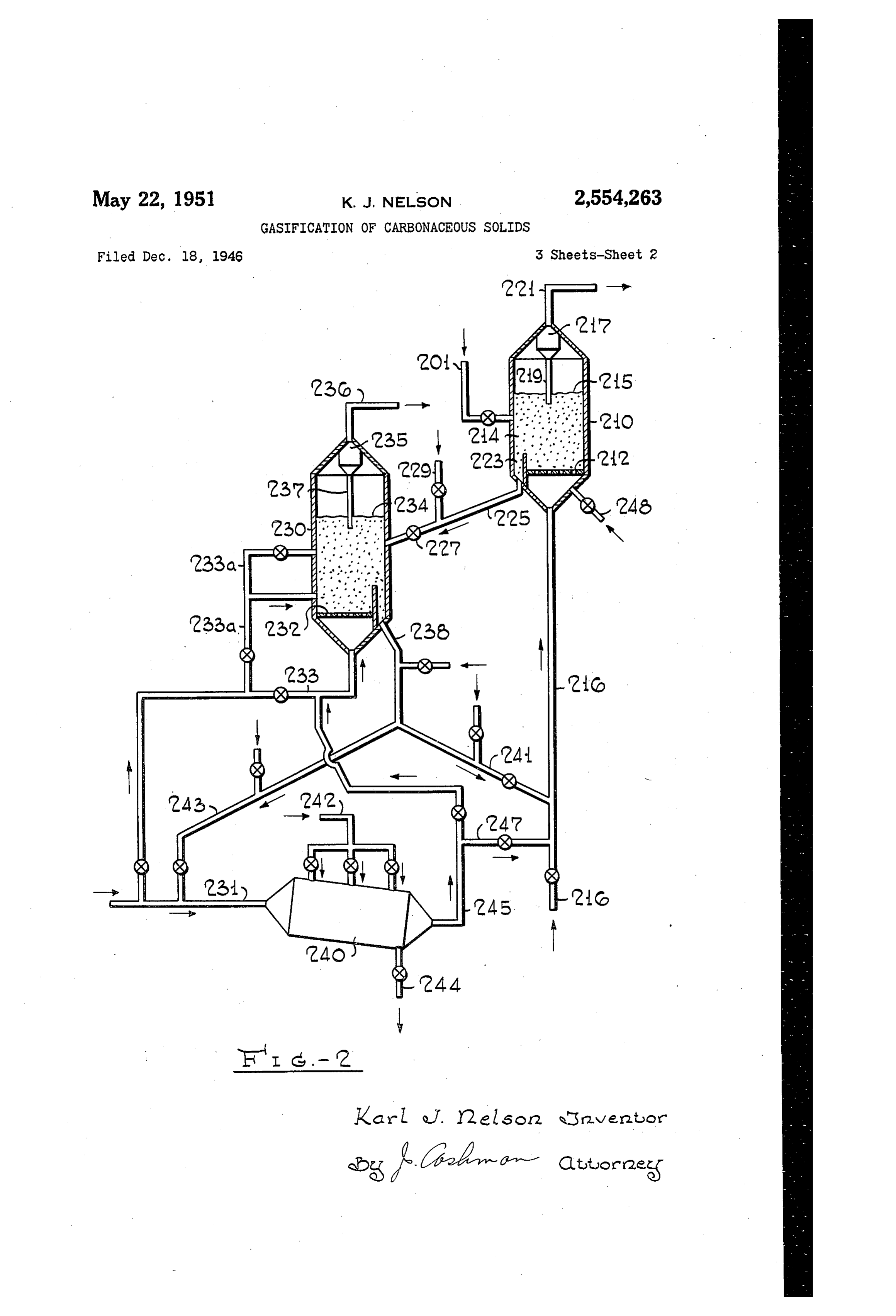
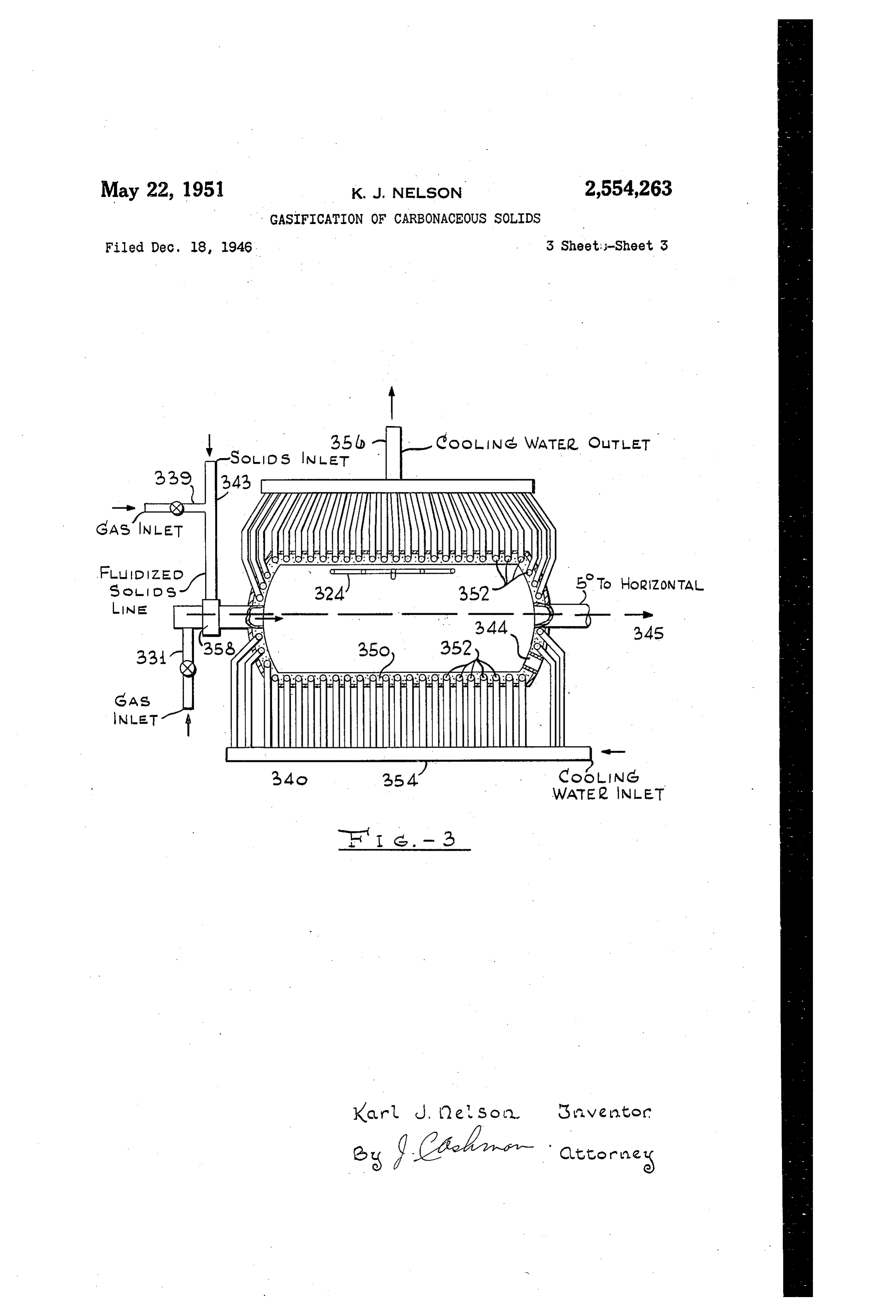
CO2 content of the fue gas, all the OXygen re Figure 2 is a similar illustration of a system quired in the gas generation Zone to convert the tlSing the Sensible heat of high temperature desired amount of carbon into carbon monoxide. Solids for the same purpose, and When water gas is produced, part or all of the Figu:'e 3 is a Semi-diagrammatical illustra steam required for the Water gas reaction may ticin of a high temperature combustion cham serve as a diluent in the combustion Zone and her suitable for the purposes of the invention. the excess oxygen from the combustion Zone may Referring now to Figure 1, the system shown be used in the gas generation Zone to generate therein essentially comprises a water gas gen additional heat therein Substantially as Outlined erator and a high temperature combustion above. Some steam dissociation and/or conver 2 ZOne or burner whose functions and coopera sion may take place at the conditions of the tion Will be forthwith explained. While low combustion zone and any hydrogen and/or car temperature coke Will be referred to hereinafter bon monoxide produced in this manner Will be as the carbonaceous Solid used any other solid recovered from the gas generator. carbonaceous material may serve as charge to In accordance with a more specific embodiment 3. riny process.
of the invention, a combustion Zone of the type In operation, a finely divided preferably highly described may be combined with a conventional reactive coke produced by the carbonization of “fluid' heater to supply heat to the gas genera a bitunainous coal in a fluidized solids bed at tion zone in the form of sensible heat of Solid temperatures not substantially exceeding 1000° heater residue. For this purpose solid gasifica 35 F. is supplied through line to gas generator tion residue of relatively high carbon concentra i. Line may be part of any conventional tion may be circulated from the fluidized gaS i.eans for conveying finely divided solids such generator bed to an external heater Wherein it as an aerated Standpipe, a pressurized feed is subjected to a combustion. With air in the form hopper, a mechanical conveyor, etc. The parti of a dense, turbulent, fluidized bed at relatively cle size of the coke may fall within the wide high carbon concentration. A major portion of ranges of A2 in. to 400 mesh, preferred size the Solid, relatively high-carbon combustion resi ranges being about as follows: due from the heater may be returned to the gas generator for heat supply therein. A minor por -70% through 200 mesh screen tion may be passed to a high temperature com to 20-40%
through 50 mesh screen through 30 mesh screen bustion zone of the type described above to com pletely burn the carbon, dispose of the ash and 80-100% through 4 in, Screen produce flue gas having a temperature far in ex The finely divided coke forms in generator cess of the temperature in the heater. This flue above distribution grid 2 a dense turbulent gas is returned to the heater. inass 4 of solids fluidized by the gaseous reac The CO2 introduced into the heater with the tion products and the gas and vapors supplied flue gases from the combustion ZOne Will, at the through line 6 and grid 2 as will appear more high carbon concentration of the heater, react clearly hereinafter. Linear gas velocities of With carbon to form CO, causing losses of heat about 0.1-10 ft. per second, preferably 0.3–3 ft. and effective carbon unless sufficient oxygen is i5 per Second, within mass 4 are generally suit present in the heater to favor the formation of able for this purpose at preSSures ranging from CO2 over that of CO. It is advisable, therefore, about atmospheric to about 400 lbs. per sq. in to maintain, for example, at least a slight exceSS and for bed densities of about 10-50 lbs. per of oxygen in the heater over that consumed by cu. ft.
the desired combustion of Solid carbon in the 60 Heat, and gaSifying mediurn Such as air, Oxy heater. This may be accomplished by Splitting gen and/or steam, depending on the product the air feed to the system in a Suitable mannel' gas desired, are supplied through line 6 suffi and feeding part of the air to the high tempera cient in amounts to maintain bed is at the ture combustion zone and part to the heater, desired gasification temperature of about 1400 if desired, in a plurality of streams. 2500 F. and at a carbon concentration of about In this manner, the heater temperature and 15-60%, preferably about 30 to 50%. At gas thus the temperature differential between heater temperatures in line 6 of about 2700°-3000 F. and gas generator may be maintained at least the amount of air required to produce producer at similar and even at higher levels as if car gas at the carbon concentrations indicated is bonaceous solids of low carbon concentration about 1.5 to 6.0 lbs. per lb. of coke charged and were burned in the heater. However, the carbon the amount of steam required to produce Wate' concentration of the heat-carrying Solids re gas is about 0.4 to 4.0 lbs. per lb. of coke charged. turned to the gas generator is now high enough Product gas is withdrawn overhead from level to establish a carbon concentration within the 5 of mass 4 and passed through a conven gas generator at levels desirable for high con 75 ticinal gas solids separator i provided With
Page 7
Solids return line 9. Gases substantially free perature in burner 40 is controlled by the exceSS of solids leave through line 2 and flow to fur of air, part of which may be admitted through ther processing equipment and/or any desired line 46. Additional air required for gas genera use such as a hydrocarbon Synthesis reactor or tion in bed 4 may be supplied through line 48. the like (not shown), if desired, after heat ex 3. The annount of total air required for the manu change with solid and/or gaseous feed materials facture of producer gas may fall within the ap of the process. proximate limits of 1.5 to 6.0 lbs. per lb. of car Solid fluidized gasification residue of the bon to be gasified.
average carbon concentration of bed 4 is with Instead of feeding the carbonaceous charge drawn downwardly through well 23 and passed through line directly to bed 4 it may be Sus under the combined pseudo-hydrostatic and gaS pended in the gasifying medium flowing through pressures of bed. A through standpipe 25 to line 6 or line 48 and passed upwardly through which a small amount of steam, air and/or grid 2 in a manner known in the art of fluid oxygen is added through taps 29 to facilitate Solids handling.
the flow and strip the solids in standpipe 25. Referring now to Figure 2, the System shown The rate of solids flow through standpipe 25 is therein essentially comprises a gas generator 20, adjusted by means of valve 2. A Solids With a fluid Solids heater 230 and a high temperature drawal rate of about .05 to 0.3 lb. per lb. of coke burner 240.
charged through line is generally adequate. Finely divided fresh coke is charged through Carbonaceous solids discharging through valve i) line 20 to generator 2 0 to form therein above 27 are suspended in a stream of Combustion-Sup grid 22 a dense turbulent bed of solids fluidized porting gas such as air and/or oxygen flowing by gas supplied through line 26 and forming an through line 3 and the suspension formed is upper level 2 5 to undergo gasification Substan blown into burner 40, preferably tangentially, tiaiiy as described in connection with generator along its axis. The amount of air and/or Oxy f3 of Figure 1. Product gas is withdrawn up gen entering burner 40 through line 3 including wardly through gas-Solids separator 2 provided any combustion-supporting gas admitted through with solids return line 29 and thence through taps 29 may be about 1-20% of the total com line 22.
bustion-supporting gas supplied to burner 40. High-carbon gasification residue flows through The remainder of the combustion-Supporting gas solids withdrawal well 223 and standpipe 225 pro required to bring the total amount of gas above vided with control valve 22 and aerated and 100%, say, to between about i05 and 600% of the stripped through one or more tapS 229 With air amount theoretically required for complete com and/or oxygen to heater 239 to form therein bustion of carbon available in burner 4 is Sup above grid 232 a dense turbulent bed of carbon plied through a manifold 42 or the like, tangen 35 aceous solids fluidized by hot, air and fiue gas tially to the combustion zone of burner 43 at a supplied through line 233 to form a well defined linear velocity of about 300-700 ft. per second, upper level 234. Linear gas velocities and bed preferably about 500 ft. per Second. Details of densities in heater 230 may be Substantially the the design of burner 40 will be described below same as those Specified in connection With gen in connection. With Figure 3 of the drawing. It erator O of Figure 1.
should be noted, however, that burner 40 may The amount and distribution of air Supplied to also be arranged in a Substantially vertical pO heater 23i) should be sufficient to prevent Sub sition with a downward flow of feed and ash. stantial reduction to CO, of CO2 present in The temperature of burner 40 is maintained heater 23i including CO2 contained in the hot above 2500 F., the desired temperatures de combustion gases issuing from burner 240 and pending on the fusion point of the ash and the entering 230 through lines 245 and 233 as will amount of carbon to be burned. Liquid ash is appear helreinafter. Proper distribution of the tapped at 44 while hot flue gases enter line 6 air fed to heater 230 may be accomplished by and generator 0 substantially at the tempera the use of one or more manifold branch lines ture of burner 40. 233a, depending on the height of the fluidized When water gas is to be produced in generator bed in heater 230.
iO by a gasification reaction. With Steam, oxygen The combined effect of combustion and high may be supplied as the combustion-Supporting OXygen Supply raises the temperature of the gas through lines 3 and 42. In order to pre Solids in heater 236 to temperatures of about vent the temperature within burner 40 from ris- ; 1500-2500° F., preferably about 1700°-1900 F., ing beyond desired levels, at least a Substantial that is, below the fusion point of the ash but proportion of the steam required for the Water Substantiaily above the desired gasification tem gas reaction may be admitted through lines 46 perature in generator bed 24. Flue gases are and/or 42 to burner 40 to act as a diluent of Withdrawn overhead from level 234 through the oxygen. Any additional Steam required to 6) cyclone separator 235 and pipe 236 to be used bring the total up to 0.4 to 4.0 lbs. per lb. of coke for any desired purpose including heat eXchange charged as it is needed for the desired gasifica With proceSS Solids and/or gases. Solids Sep tion may be added through line 48 directly to arated in separator 235 may be returned through generator . Burner temperatures of about pipe 23d to heater 230.
2700°-3300° F. are generally suitable for most of Solid fillidized combustion residue from heater the conventional carbonaceous charge materials. 23 is withdrawn through standpipe 238 and Excess oxygen entering generator i? burns an passes Substantially at the temperature of heater equivalent amount of combustibles in bed 4 to 23 through branch standpipe 24f into line 26 generate additional heat therein. In general, a Where it is Suspended in the gaseous gasifying total of 0.2 to 2.0 lbs. of oxygen charged to the () medium and carried through grid 22 into gen burner per ib. of carbon to be gasified is Suf erator 2 ft) to Supply the heat required for gasi ficient for the production of water gas. fication. As a result of the high temperature When generator 8 is to be used for the manu and high carbon concentration of the Solids so facture of producer gas, air instead of oxygen is Supplied, the carbon concentration in generator Supplied through lines 3 and 42 and the tem 2f remains as high as about 15 to 60%, prefer
Page 8
ably about 30 to 56%, at gasification temper the general principles of design and operation atures of about 1400°-2500 F. Solids circula of burners of this type have been suggested by tion rates through standpipe 24 of about 50 to others prior to the present invention their 500 lbs. per lb. of carbon to be gasified are gen Specific adaptation to the gasification of car. erally Sufficient for this purpose at the condi bonaceous Solids employing the fluid solids tions indicated. technique forms an essential element of the A minor proportion of the solids entering present invention.
Standpipe 238 is branched off to standpipe 243 The burner, as illustrated, rray consist of an and fed to line 23 wherein it is suspended in Outer Steel shell 34 provided with an inner re air and thence Supplied to burner 24 for com O fractory lining 353 preferably of chrone ore plete combustion at temperatures above the ash having a fusion point not Substantially below fusion point. Substantially as outlined in con 200 F. Cooling tubes 352 are imbedded in the nection with burner 40 of Figure 1. Secondary refractory lining and Supplied with cooling water high velocity air is admitted tangentially through through water header 354. Heated water and/ manifold 242 to bring the total combustion air or Steain is withdrawn from the cooling tubes above the amount theoretically required for 352 through header 356. Manifold 324, prefer Complete combustion. Liquid ash is withdrawn ably in the top of the combustion zone, serves through tap. 244 and hot flue gases pass at a the introduction of high velocity secondary con temperature of about 2500°-3300° F through bustion-Supporting gas and/or diluent. lines 245 and 233 to heater 23 as outlined above. 20 Carbonaceous solids having a particle size It will be understood that the amount of Substantially as described above are Supplied Solids circulated through standpipe 225 will de from the gas generator or heater through stand pend on the feed rate of carbonaceous charge. pipe 343. About 1-15% of the total combustion and the rate of Solids circulation through stand Supporting gas required may be added through pipe 23 and pipe 2 S. so that major fluctuations 25 tap 339. The fuidized solids fow under the of level 23 will be avoided. For similar reasons preSSure of Standpipe 343 to feed device 333 ar the rate of Solids withdrawal through standpipe ranged on the horizontal axis of cylindrical shell 233 Will depend on the rate of solids supply 340. An additional amount of about 1-5% of the through standpipe 225. In general, solids cir total combustion-supporting gas may be added culation rates through standpipe 225 of about 30 through iine 33.
50 to 500 lbs, per lb. of coke charged through The Solids-gas mixture enters shell 343 tan line 28 and of about 49 to 499 lbs. through gentially along the axis, a more violently rotat Standpipe 238 per lb. of coke charged through ing motion being imparted to the combustion line 26 are adequate for the purposes of the mixture by the tangential high velccity second invention. 35 ary combustion-Supporting and/or diluent gas The exact l'eaction conditions in generator Supplied through 324, which may amount to as it depend on the kind of product gas desired. much as 98% of the total combustion-supporting For the production of water gas, steam is Sup gaS. The burner is operated above ash fusion plied thi'Oilgh lines 26 and temperatures of temperature and liquid ash is withdrawn through about 1400°-1900 F. and pressures of atmos 40 a bottom orifice 344 close to the lower discharge peric to about 400 lbs. per sq. in may be used, end of the burner. Hot flue gases are withdrawn the higher pressure ranges being conducive to through port 345 for further use in the process, the formation of a high B. t. u. gas rich in preferably after passing through an entrainment gaseous hydrocarbons. For the manufacture of Separator wherein entrained fluid ash may be re producer gas the same or higher temperatures, moved in any conventional manner. Say 2000-2400° F., and similar pressures may The Violent SWirling action of the combustion be applied while predominantly air, if desired, mixture causes an extremely intimate contact a dinixed with Some steam is supplied through between fuel and combustion-supporting gas and line 25. makes possible the attainment of extremely high if desired, additional heat may be supplied to 50 combustion temperatures in a relatively small generator 2 ( in the form of hot, normally oxy combustion space. The cooling tubes 352 are gen-containing burner flue gases branched off operated so as to maintain the refractory lining line 285 to lines 24 and 26, or a combustion in an effective operating condition, while with Supporting gaS Such as air and/or oxygen may drawing only a minimum amount of heat from be added to generator 2 a through line 246 or 55 the chamber.
243 to Support a limited combustion within bed The absolute dimensions of the burner depend, 2. of course, on the output desired. It may be It Will be understood that in place of any one Stated, however, that a combustion space of about or all of standpipes 225, 238, 25 and 243 other 1 to 20 cu. ft. per 1,000 lbs. of coal per hour to conventional means for conveying fluidized 60 be gasified in generators or 2 is generally Solids Such as mechanical conveyors of various Sufficient. Many modifications of the burner types may be used. It should also be noted that illustrated in Figure 3 may occur to those skilled heater 239 may be arranged at higher level than in the art without deviating from the spirit of generator 2 so that solids flow is by gravity the invention.
from heater 238 to generator 2 0 and by Way of 85 While I have described above Specific burner combined gas and pseudo-hydrostatic pressure means suitable for the purposes of my process, the in the Opposite direction. As stated before, present invention is not limited to these specific burner 24 may also be arranged in a vertical means but is intended to include any means for position. Other modifications within the scope Completely burning finely divided carbonaceous Of Iy invention will appear to those skilled in 70 Solids of a high carbon concentration, say, above the art. about 15% attemperatures above the fusion point Referring now to Figure 3, I have illustrated of the ash.
therein in greater detail a high temperature It should also be understood that certain of the burner of the type schematically shown at 43 advantages of my invention will be realized when and 240 of Figures 1 and 2 respectively. While s fixed or moving beds or dilute solids-in-gas Sus
Page 9
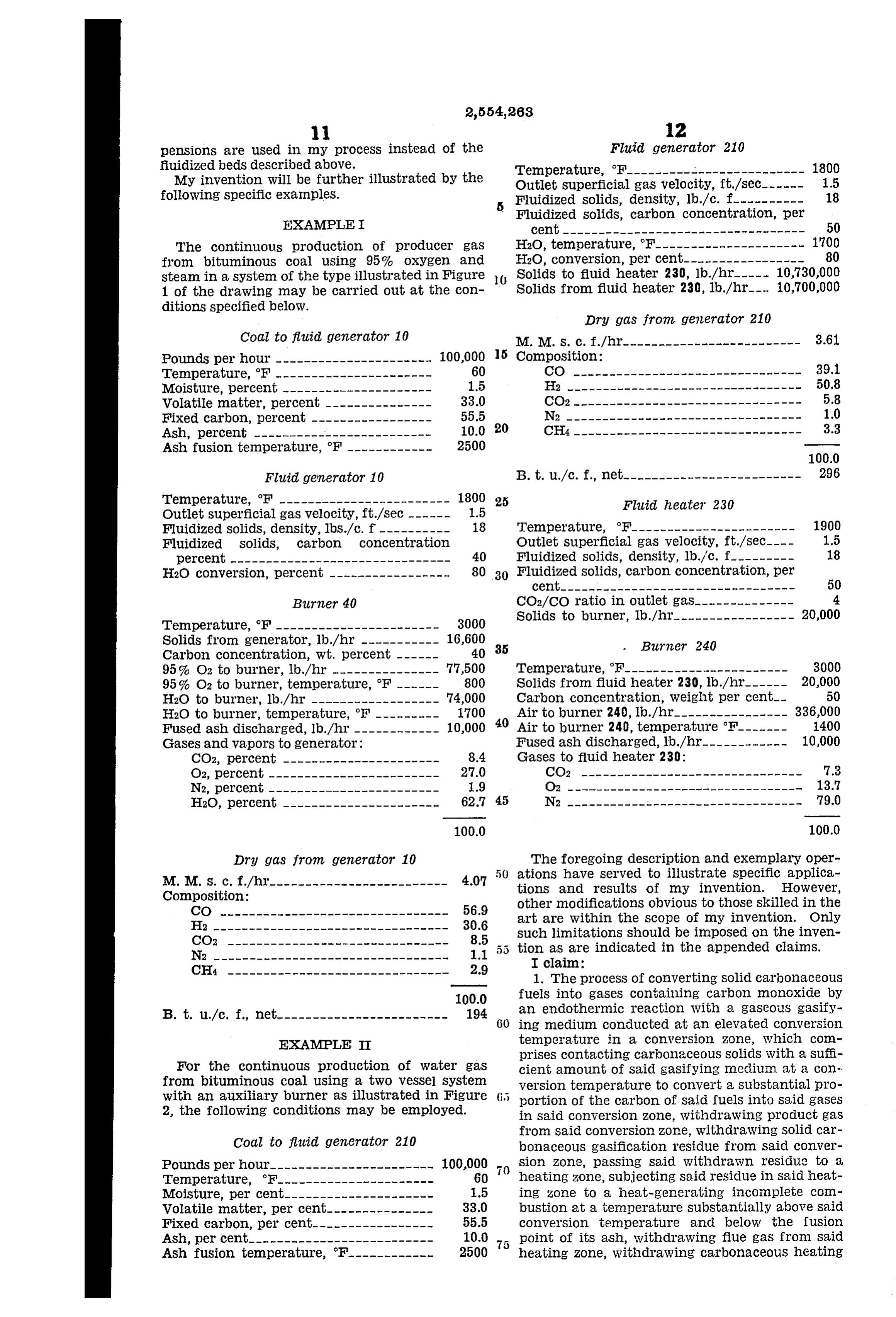
pensions are used in my process instead of the Fluid generator 210 fluidized beds described above. Temperature, F------------------------- 1800 My invention will be further illustrated by the Outlet Superficial gas velocity, ft/sec.------ 1.5 following specific examples. Fluidized Solids, density, lb./c. f---------- 18
EXAMPLE
Fluidized solids, carbon concentration, per
The continuous production of producer gas H2O, temperature, F--------------------- 1700 from bituminous coal using 95% oxygen and H2O, conversion, per cent----------------- 80 steam in a system of the type illustrated in Figure O Solids to fluid heater 230, lb./hr-l... 10,730,000 1 of the drawing may be carried out at the Con Solids from fluid heater 230, lb./hr. 10,700,000 ditions specified below.
Dry gas from generator 210
Coal to fluid generator 10 M. M. S. C. f./hr------------------------- 3.6 Pounds per hour ---------------------- 100,000 5 Composition:
Temperature, F ---------------------- 60 CO -------------------------------- 39. Moisture, percent --------------------- 1.5 He --------------------------------- 50.8 Wolatile matter, percent --------------- 33.0 CO2 -------------------------------- 5.8 Fixed carbon, percent ----------------- 55.5 N2 --------------------------------- 1.0 Ash, percent ------------------------- 10.0 20 CH4 -------------------------------- 3.3
Fluid generator 10 B.t. u./c.f., net------------------------- 296 Temperature, F ------------------------ 1800 25 Fluid heater 230 Outlet Superficial gas velocity, ft./Sec ------ 1.5
Fluidized solids, density, lbs./c. f---------- 18 Temperature, F----------------------- 1900 Fluidized solids, carbon concentration Outlet Superficial gas velocity, ft./sec.---- 1.5 percent ------------------------------- 40 Fluidized Solids, density, lb./c. f--------- 18 H2O conversion, percent ----------------- 80 30 Fluidized solids, carbon concentration, per
Birner 40 CO2/CO ratio in outlet gas-------------- 4 Temperature, F----------------------- 3000 Solids to burner, lb./hr.----------------- 20,000 Solids from generator, lb./hr ----------- 16,600 35 Birzer 240 Carbon concentration, Wt. percent ------ 40 95% O2 to burner, lb./hr --------------- 77,500 Temperature, F----------------------- 3000 95% O2 to burner, temperature, F ------ 800 Solids from fluid heater 230, lb./hr------ 20,000 H2O to burner, lb./hr ------------------ 74,000 Carbon concentration, weight per cent- 50 H2O to burner, temperature, F --------- 1700 40 Air to burner 240, lb./hr.---------------- 336,000 Fused ash discharged, lb./hr ------------ 10,000 Air to burner 240, temperature F------- 400 GaSes and vapors to generator: Fused ash discharged, lb./hr.------------ 10,000 CO2, percent ---------------------- 8.4 Gases to fluid heater 230:
O2, percent ------------------------ 27.0 CO2 ------------------------------- 7.3 N2, percent ------------------------ 1.9 O2 --------------------------------- 13.7 H2O, percent ---------------------- 62.7 45 N2 --------------------------------- 79.0
Dry gas from generator 10 The foregoing description and exemplary oper ations have served to illustrate specific applica
Composition: and results of my invention. However, CO -------------------------------- 56.9 other modifications obvious to those skilled in the H --------------------------------- 30.6 art are within the Scope of my invention. Only
tion limitations should be imposed on the inven as are indicated in the appended claims.
1. The process of converting Solid carbonaceous 100.0 fuels into gases containing carbon monoxide by
B. t. u/c. f., net------------------------ 194 60 an endothermic reaction with a gaseous gasify ing medium conducted at an elevated conversion
EXAMPLE II temperature in a conversion zone, which con prises contacting carbonaceous solids with a suffi
For the continuous production of water gas cient amount of Said gasifying Inedium at a con from bituminous coal using a two vessel system version temperature to convert a substantial pro with an auxiliary burner as illustrated in Figure portion of the carbon of Said fuels into Said gases 2, the following conditions may be employed. in said conversion zone, withdrawing product gas from said conversion Zone, withdrawing Solid car
Coal to fluid generator 210 bonaceous gasification 1'esidue from said conver Pounds per hour----------------------- 100,000 Sion Zone, passing said withdrawn residue to a Temperature, F---------------------- 60 heating zone, subjecting said residue in Said heat Moisture, per cent--------------------- 1.5 ing zone to a heat-generating incomplete com Volatile matter, per cent--------------- 33.0 bustion at a temperature substantially above said Fixed carbon, per cent.----------------- 55.5 Conversion temperature and below the fusion Ash, per cent-------------------------- 10.0 75 point of its ash, withdrawing flue gas from Said Ash fusion temperature, F------------ 2500 heating Zone, withdrawing carbonaceous heating
Page 10
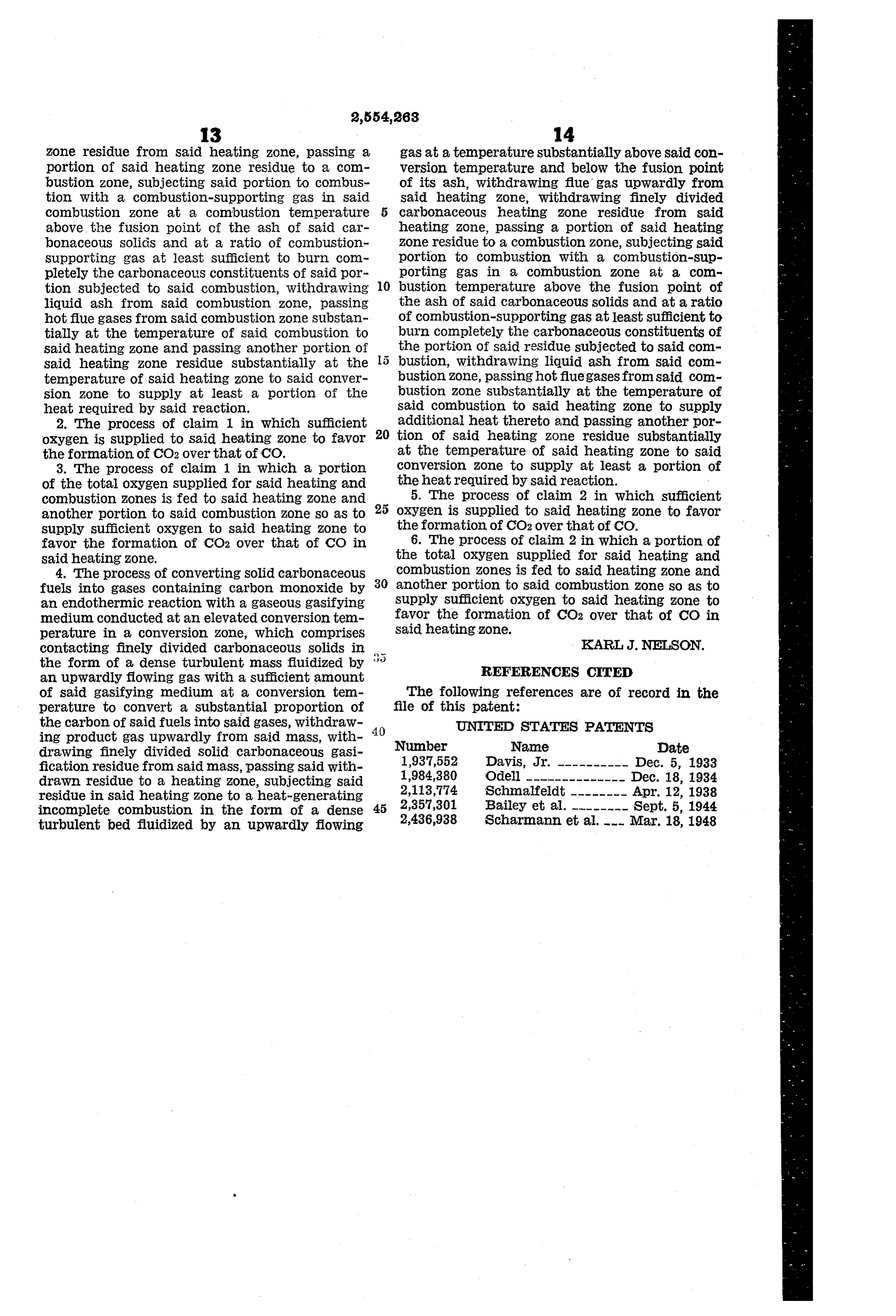
Zone residue from said heating Zone, passing a gas at a temperature substantially above Said con portion of Said heating Zone residue to a com Version temperature and below the fusion point bustion zone, Subjecting said portion to combus of its ash, withdrawing flue gas upwardly from tion. With a combustion-supporting gas in Said said heating Zone, withdrawing finely divided combustion Zone at a combustion temperature carbonaceous heating ZOne residue from said above the fusion point of the ash of said car heating Zone, passing a portion of said heating bonaceous Solids and at a ratio of combustion Zone residue to a combustion zone, subjecting said Supporting gas at least Sufficient to burn Com portion to combustion. With a combustion-Sup pletely the carbonaceous constituents of Said por porting gas in a combustion zone at a com tion subjected to said combustion, withdrawing 10 bustion temperature above the fusion point of liquid ash from Said combustion Zone, passing the ash of Said carbonaceous solids and at a ratio hot fue gases from said combustion zone Substan of combustion-supporting gas at least sufficient to tially at the temperature of Said combustion to burn completely the carbonaceous constituents of said heating zone and passing another portion of the portion of said residue subjected to said com said heating zone residue substantially at the bustion, Withdrawing liquid ash from said com temperature of Said heating zone to Said Conver bustion Zone, passing hot flue gases from said com sion zone to supply at least a portion of the bustion ZOne substantially at the temperature of heat required by Said reaction. said combustion to Said heating zone to supply 2. The process of claim 1 in which sufficient additional heat thereto and passing another por oxygen is supplied to Said heating Zone to favor 20 tion of Said heating Zone residue substantially the formation of CO2 over that of CO. at the temperature of said heating zone to said 3. The process of claim 1 in Which a portion Conversion Zone to Supply at least a portion of of the total oxygen Supplied for said heating and the heatrequired by said reaction. W combustion Zones is fed to said heating ZOne and 5. The process of claim 2 in which sufficient another portion to Said combustion Zone so as to 25 Oxygen is Supplied to said heating zone to favor supply sufficient OXygen to said heating ZOne to the formation of CO2 over that of CO. favor the formation of CO2 Over that of CO in 6. The process of claim 2 in which a portion of said heating ZOne. the total oxygen Supplied for said heating and 4. The process of converting Solid carbonaceous Combustion Zones is fed to said heating zone and fuels into gases containing carbon monoxide by 30 another portion to said combustion zone so as to an endothermic reaction. With a gaseous gasifying Supply Sufficient oxygen to said heating zone to medium conducted at an elevated conversion tem favor the formation of CO2 over that of CO in perature in a conversion Zone, Which comprises said heating zone.
contacting finely divided carbonaceous Solids in KARI, J. NELSON. the form of a dense turbulent mass fluidized by REFERENCES CITED an upwardly flowing gas With a sufficient amount of said gasifying medium at a conversion tem The following references are of record in the perature to convert a substantial proportion of file of this patent:
the carbon of Said fuels into said gases, withdraw 40 UNITED STATES PATENTS ing product gas upwardly from said mass, with Number Name Date drawing finely divided solid carbonaceous gasi fication residue from said maSS, passing said with 1937,552 Davis, Jr. ---------- Dec. 5, 1933 drawn residue to a heating zone, subjecting said 1984,380 Odell -------------- Dec. 18, 1934 reside in Said heating Zone to a heat-generating 2,113,774 Schmalfeldt -------- Apr. 12, 1938 incomplete combustion in the form of a dense 45 2,357,301 Bailey et al. -------- Sept. 5, 1944 turbulent bed fluidized by an upwardly flowing 2,436,938 Schairmann et al. --- Mar. 18, 1948
Provenance
- Collection
- Cited prior art
- Original PDF
- patentimages.storage.googleapis.com →
- Filed
- 1946-12-18
- Pages
- 10
- Method
- pdftotext (the PDF's own text layer) + pdftoppm 300dpi page scans
- Source
- Google Patents bibliographic record
- Granted
- 1951-05-22
- Inventors
- Karl J Nelson; Standard Oil Development Co
- Transcribed from
- patentimages.storage.googleapis.com →