patent · US20140035509A1
System for storing electrical power
6 February 2014
Page 1 — bibliographic record
(19) United States (12) Patent Application Publication (10) Pub. No.: US 2014/0035509 A1
Baruh (43) Pub. Date: Feb. 6, 2014 (54) SYSTEM FOR STORING ELECTRICAL Publication Classification
POWER
(76) Inventor: Bradford G. Baruh, Hillsborough, CA H02. 7/00 (2006.01) (US) B65G 67/02 (2006.01)
(21) Appl. No.: 14/000,046 (52) U.S. Cl.
(22) PCT Filed: Feb. 21, 2012 (2013.01); B65G 6702 (2013.01)
S371 (c)(1), (57) ABSTRACT (2), (4) Date: Oct. 25, 2013 A wind turbine, which includes a base, a tower, the tower having a cavity therein, which houses a rechargeable battery, (30) Foreign Application Priority Data and one or more blades, which produce a source of electricity, which is stored in the rechargeable battery housed in the tower
Feb. 18, 2011 (US) .................................. 13/030,386 of the wind turbine.
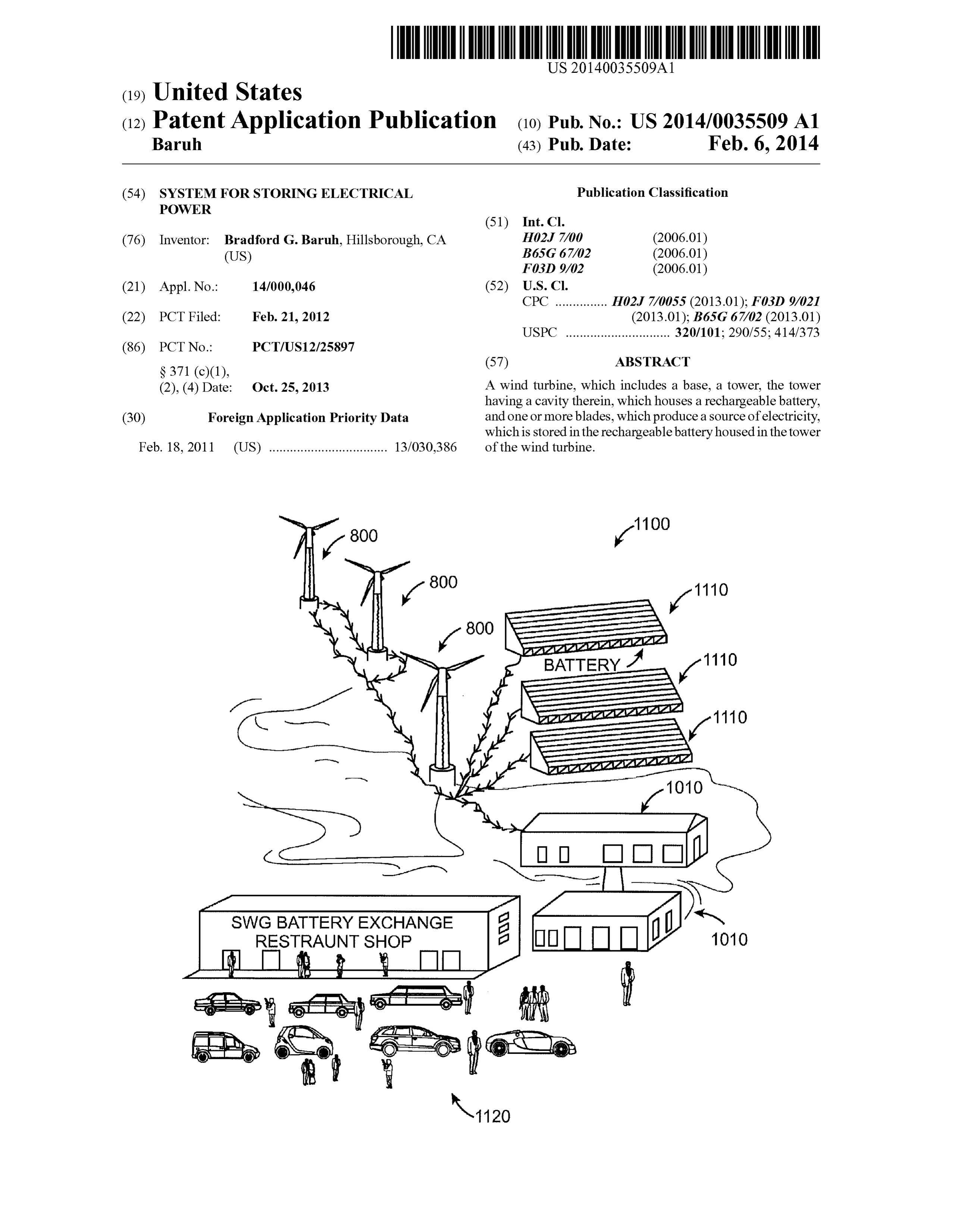
SWGBATTERY EXCHANGE
RESTRAUNT SHOP
Page 2
Drawing sheet — no readable text.
Page 3
Drawing sheet — no readable text.
Page 4
Drawing sheet — no readable text.
Page 5
Drawing sheet — no readable text.
Page 6
Drawing sheet — no readable text.
Page 7
Drawing sheet — no readable text.
Page 8
Drawing sheet — no readable text.
Page 9
Drawing sheet — no readable text.
Page 10
Drawing sheet — no readable text.
Page 11
Drawing sheet — no readable text.
Page 12
Drawing sheet — no readable text.
Page 13
Drawing sheet — no readable text.
Page 14
Drawing sheet — no readable text.
Page 15
Drawing sheet — no readable text.
Page 16
Drawing sheet — no readable text.
Page 17
Drawing sheet — no readable text.
Page 18
Drawing sheet — no readable text.
Page 19
US 2014/0035509 A1 Feb. 6, 2014
SYSTEM FOR STORINGELECTRICAL have been based upon the observation that the centerboard or POWER keel moving through the water is somewhat similar to the wing of an airplane that creates a lift as the wing is moved
FIELD OF THE INVENTION through the air. The liftofanairplane wing causes the airplane 0001. This invention generally relates to a system and to move upward against the force of gravity, and the corre method of reducing leeway drift of a sailboat as the sailboat sponding lift of a sailboat centerboard or keel that extends reaches an upwind objective by adjusting the location and downwardly can cause the sailboat to be lifted in the upwind position of the foresail (i.e., headsail.jib, genoa, or spinnaker) direction, thereby countering the sideways drift producing the leeway.
and/or adjusting the depth of the keel and/or keel foil, and 0007 Fixed keels are typically used in larger sailboats. more particularly to a system and method of adjusting the location and position of the foresail (headsail, jib, genoa, or The keels are usually filled with lead or other dense material spinnaker) on a sailboat by moving the location or position of to act as ballast for the sailboat. For example, the keels of the foresail and the forestay relative to the bow of the sailboat 12-meter sailboats may extend 10 feet below the surface of and/or by adjusting the depth of the keel and/or keel foil. the water, and weigh 40,000 to 50,000 pounds. 0008. It would be desirable to have a system or method of
BACKGROUND adjusting or changing the relative position of the fixed con nection of the foresail. Such that the angle of attack in the 0002 Typically, a sailboat includes a hull that sits in the windward direction is slightly altered in the direction of the water, a mast extending upwardly from the hull, sails Sup wind. Accordingly, it would be desirable to have a system ported by the mast, and either a centerboard or fixed keel and/or method of changing the angle or direction of the boat extending downwardly from the hull into the water. The sails in a windward direction and/or use of an extendable keel, catch the wind and cause the hull to move forwardly through which is capable of providing a lifting force to counteract the water. Although, a sailboat cannot sail directly into the leeway, and is sufficiently reliable to be acceptable for general wind, a sailboat can sail in a generally windward direction. It and racing use.
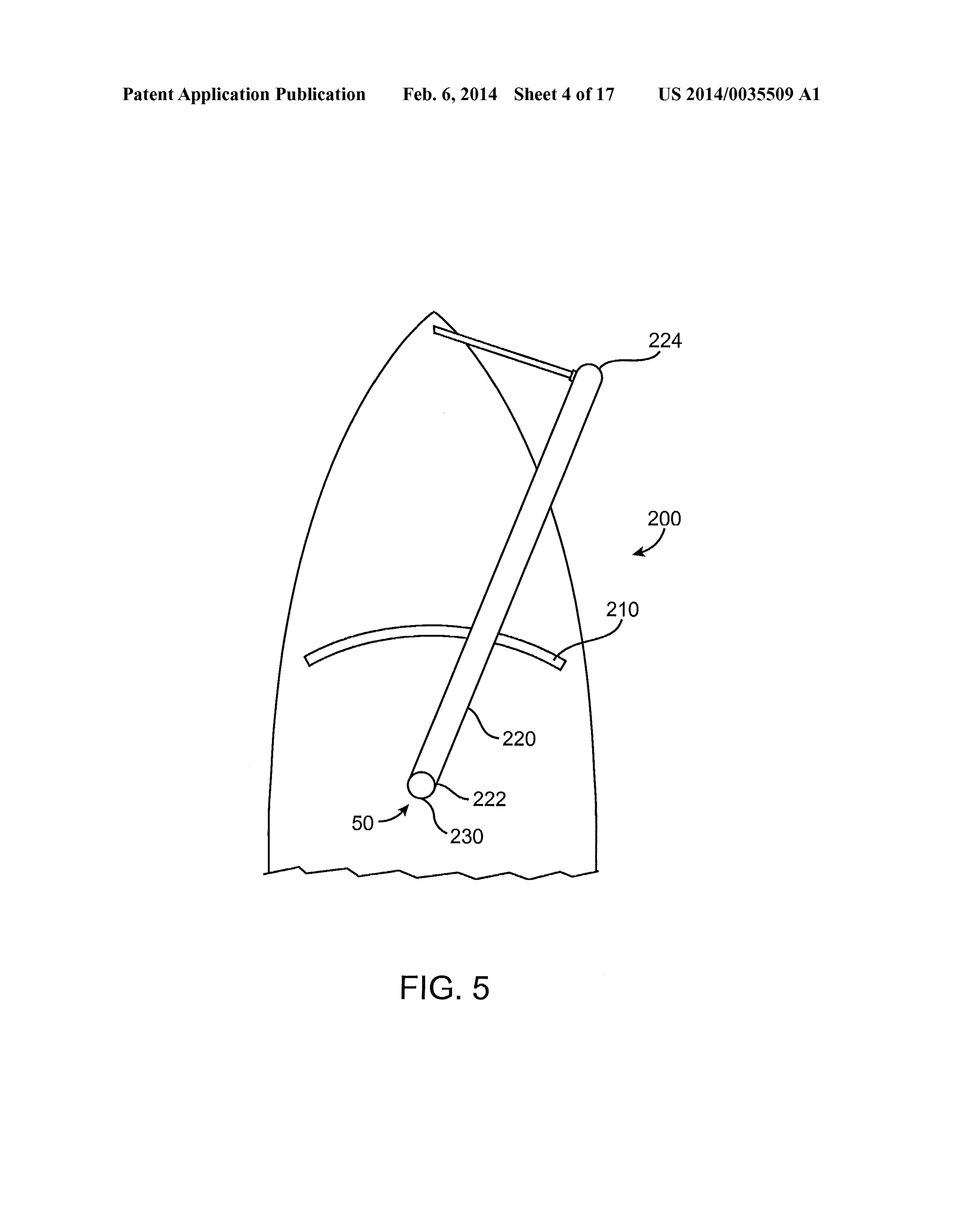
can be appreciated that with skill and a combination of 0009. In addition, it would be desirable to have a retract maneuvers, a sailor can maneuver a sailboat in almost any able Solar panel system, which can provide a source of energy desired direction. to the sailboat. The Solar panel system can be attached to a 0003 Because of the design of the sails, a sailboat can sail nautical stay, wherein the stay is fixed at one end to a hull of to windward, which is typically in a direction no less than the sailboat and at a second end to a mast of the sailboat. The about 15 to 25 degrees from the wind, depending upon the Solar panel system includes a plurality of Solar panels, which design of the boat and the skill of the sailor. Headway directly are attached to a system for extending and retracting the upwind or windward is typically achieved in a series of plurality of Solar panels, such that when not in use, the Solar sequential maneuvers called tacks, in which the boat is first panels can be stacked.
sailed windward with the wind over one side of the bow, and then turned through the wind so that the wind conies over the SUMMARY other side of the bow. In each tack, Some headway upwind is achieved even though the boat does not move directly into the 0010. In accordance with one embodiment, a system for wind, and eventually the sailboat reaches an upwind objective sailing windward comprises: a moveable track fixture; a fixed after sailing a Zig-Zag course covering a distance greater than track configured to receive the track fixture; and a control the straight line distance from the initial position to the system for securing the location of the track fixture within the upwind objective. fixed track relative to a bow of a sailboat. 0004. When a sailboat sails to windward, the forces on the 0011. In accordance with a further embodiment, a sailboat sails can be resolved into a thrust component that moves the comprises: a hull; a mast; a plurality of sails, wherein at least sailboat forwardly through the water and a drift component one of the plurality of sails is a foresail; and a system for that pushes the sailboat sideways in a downwind direction. sailing windward comprising: a moveable track fixture; a The sailboat thereforemoves in a net direction that is forward, fixed track configured to receive the track fixture; a control but also is slight downwind opposite to the net intended system for securing the location of the track fixture within the direction of movement. The sideways drift is called leeway or fixed track relative to a bow of a sailboat; and a forestay “slide slipping.” attached to the track fixture, the forestay extending from an 0005. The downwardly projecting centerboard or keel of upper portion of a mast of a sailboat to the moveable track the sailboat offers resistance to the leeway produced by the fixture on a bow of the sailboat.
sideways sail force, but at least some leeway remains. This 0012. In accordance with another embodiment, a method leeway is being constantly accumulated, as there is a down of reducing leeway drift of a sailboat as the sailboat reaches an wind movement as long as the sailboat is being sailed into the upwind objective, the method comprises changing the rela wind. The leeway significantly increases the time required for tive position of a foresail to a bow of the sailboat without the sailboat to sail from its downwind starting position to the changing the relative position of a mainsail and the foresail to upwind objective, as it forces the sailboat to sail much further one another.
to make up for the accumulated sideways movement. 0013. In accordance with a further embodiment, a sailboat 0006 Attempts have been made to reduce the amount of comprises: at least one hull; a mast; a plurality of sails, leeway. For example, a movable centerboard or fixed keel wherein at least one of the plurality of sails is a foresail; and extending into the water below the sailboat presents a broad a system for sailing windward comprising: a foresail beam surface to resist sideways drift. There have also been attempts attached to the mast of the sailboatata mastend of the foresail to modify the shape of the centerboard or keel to provide a beam and receives a leading edge of the foresail at a bow end lifting force to counteract the sideways drift. These attempts of the foresail beam; and a foresail track, which extends from
Page 20
US 2014/0035509 A1 Feb. 6, 2014
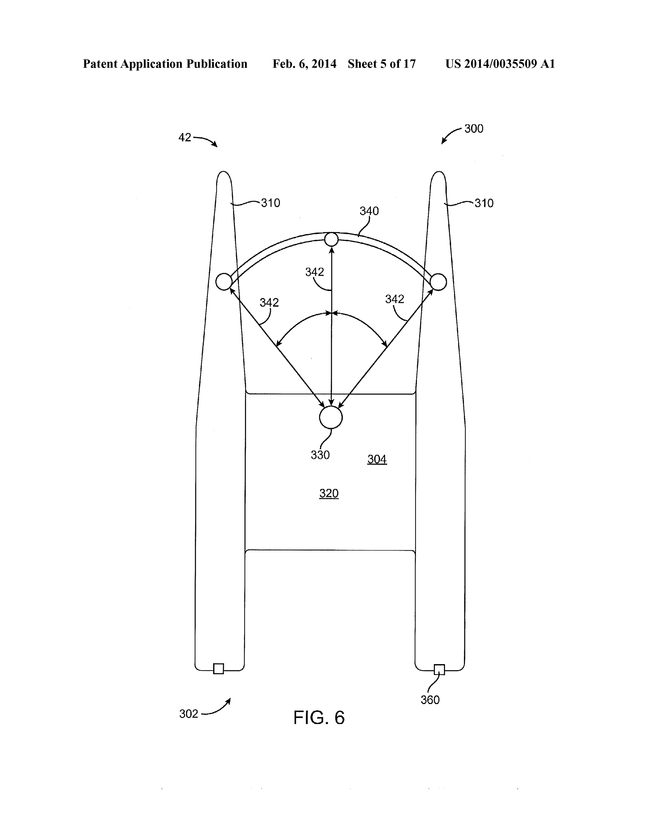
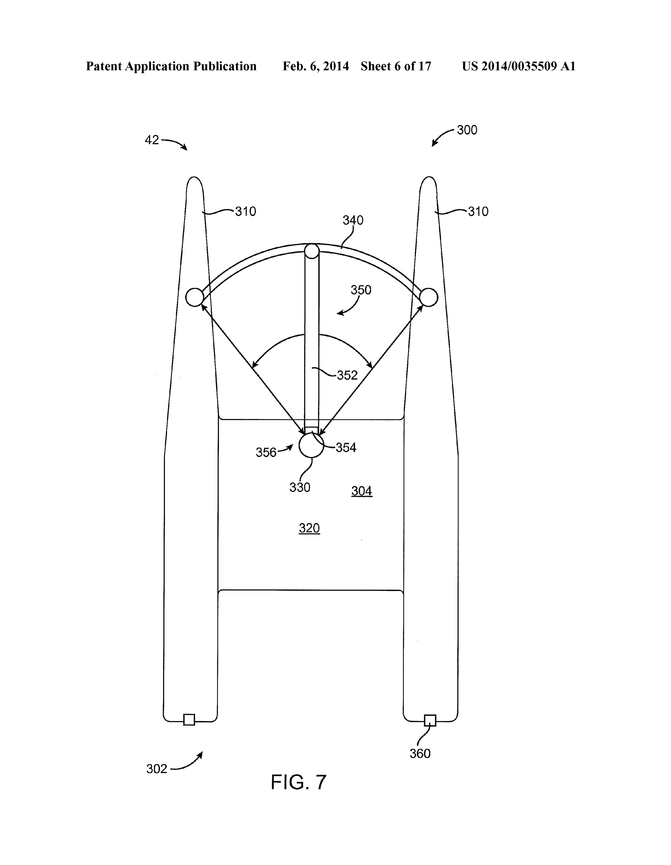
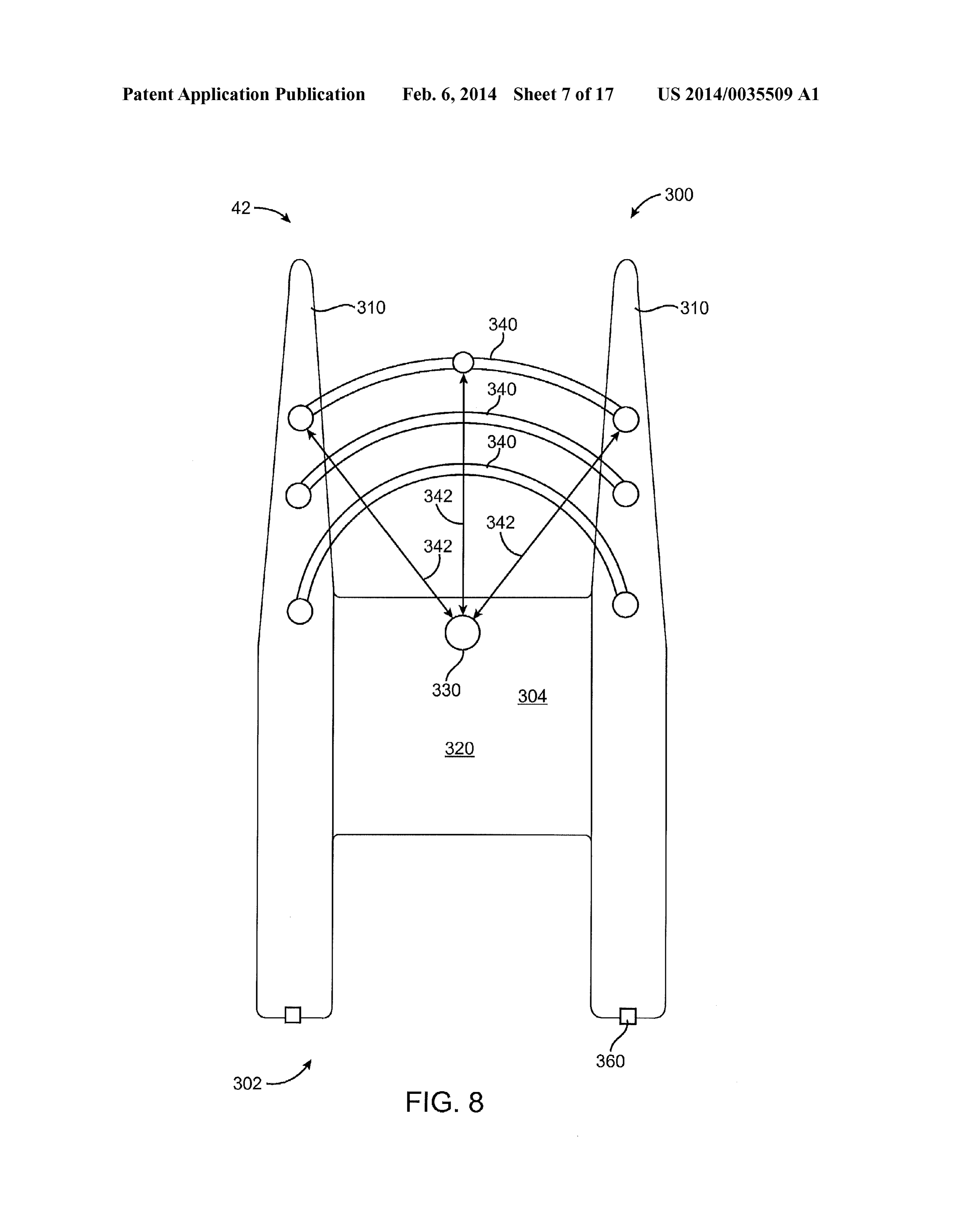
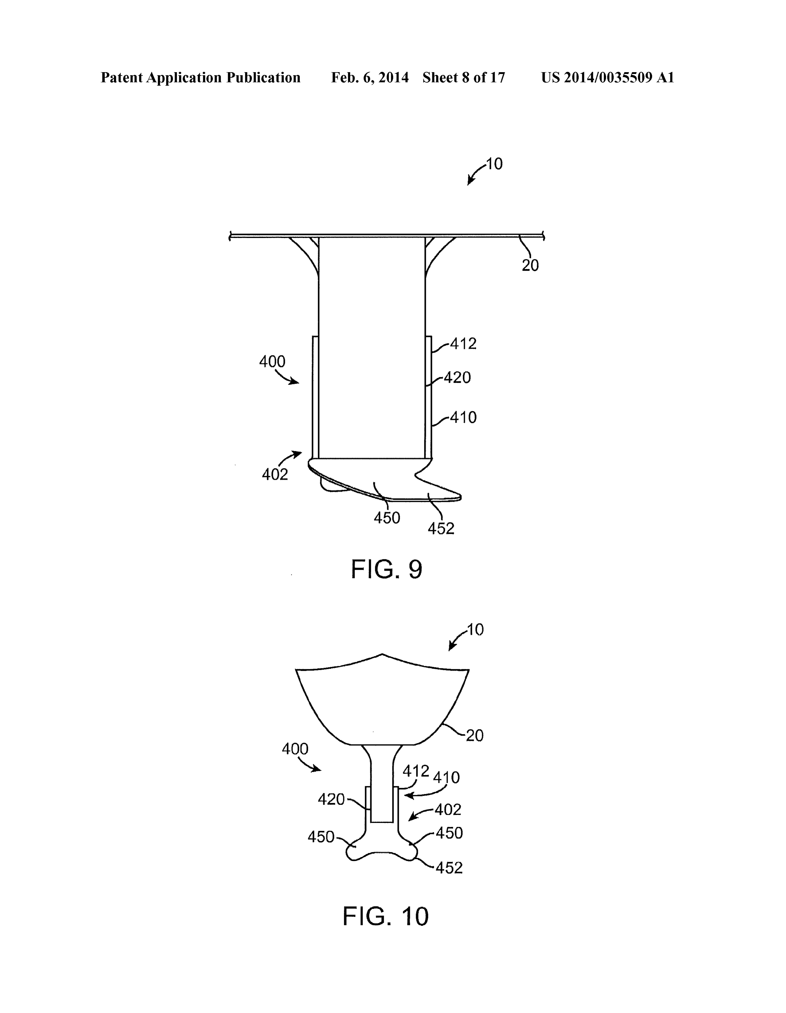
a starboard side to a port side of the sailboat and assists the (0025 FIG. 6 is a top view of a multi-hulled boat with a foresail beam in movement from side to side. system and method of adjusting the location and position of 0014. In accordance with another embodiment, a sailboat the foresail in accordance with a further embodiment. comprises: two or more hulls; a plurality of sails, wherein at (0026 FIG. 7 is a top view of a multi-hulled boat with a least one of the plurality of sails is a foresail; and a system for system and method of adjusting the location and position of sailing windward, which includes a foresail track, which the foresail in accordance with another embodiment. receives a leading edge of the foresail and extends from one of 0027 FIG. 8 is a top view of a multi-hulled boat having the two or more hulls to another of the two or more hulls. one or more track systems for adjusting the location and 0.015. In accordance with a further embodiment, a sailboat position of the foresail in accordance with a further embodi comprises: two or more hulls; a plurality of sails, and wherein ment.
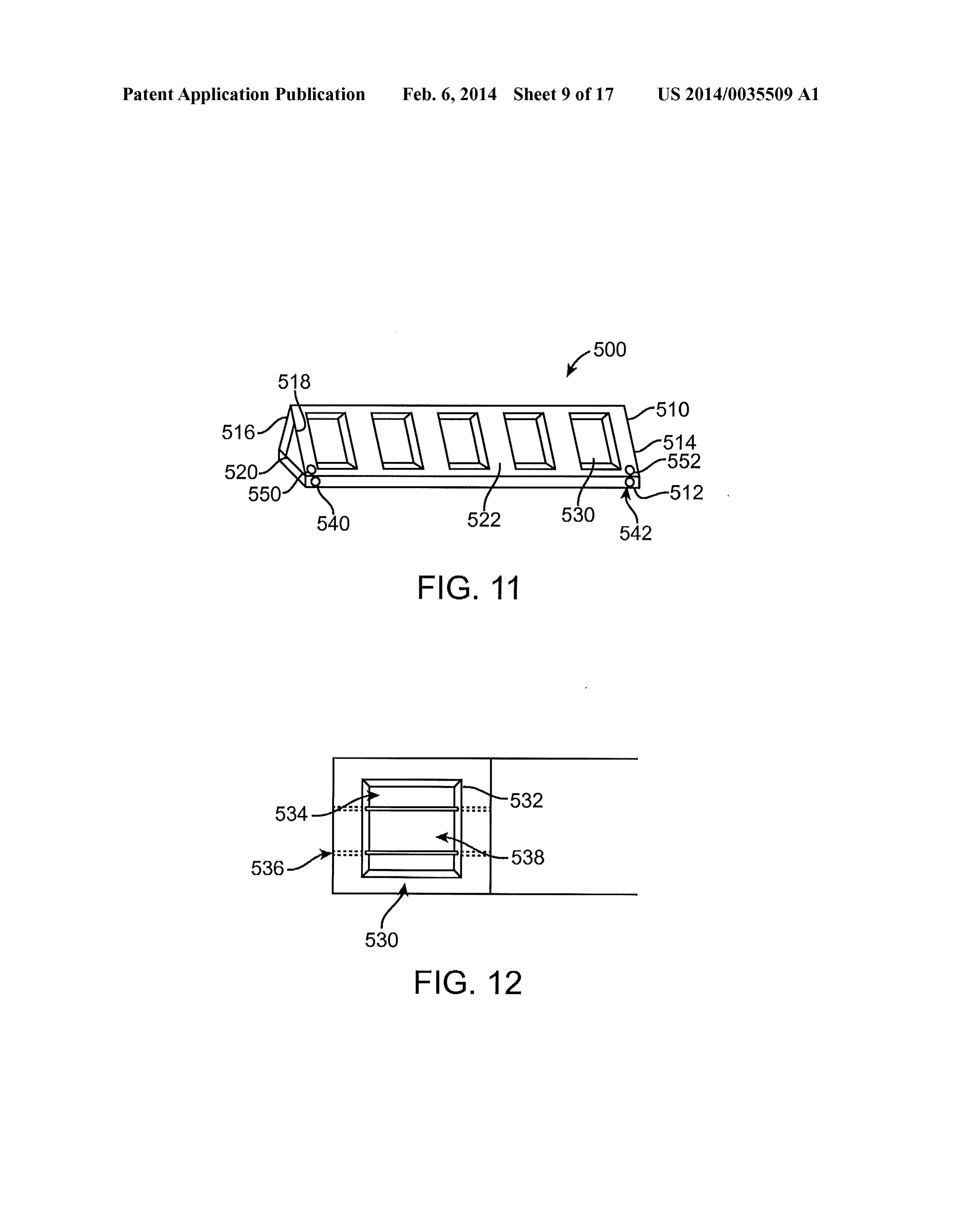
the plurality of sails includes one or more foresails; and a 0028 FIG. 9 is a cross-sectional view of a portion of a system for sailing windward, which includes two or more sailboat with a fixed keel and an adjustable ballast or weight foresail tracks, each of the two or more foresail tracks is system in accordance with a further embodiment. configured to receive a leading edge of a foresail, and wherein 0029 FIG. 10 is a cross-sectional view of a sailboat with a each of the foresail tracks extend from one of the two or more fixed keel in accordance with another embodiment. hulls to another of the two or more hulls. 0030 FIG. 11 is a perspective view of an inflatable solar 0016. In accordance with another exemplary embodiment, panel system in accordance with an embodiment. an extendable keel comprises: a fixed inner member, a move 0031 FIG. 12 is a plan view of a portion of the inflatable able outer member, the moveable outer member surrounding solar panel system of FIG. 11 in accordance with an embodi the fixed inner member; a foil member attached to the outer ment.
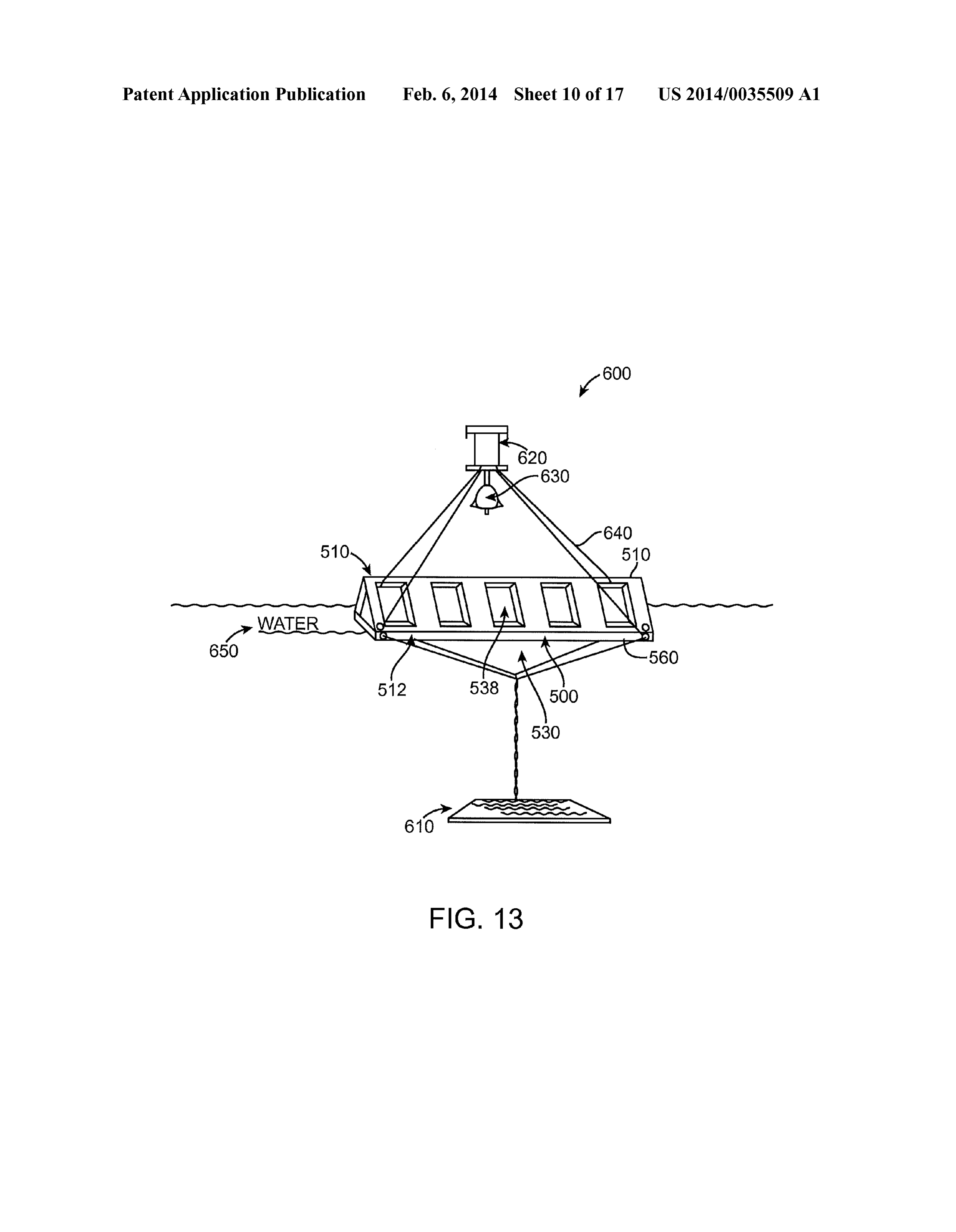
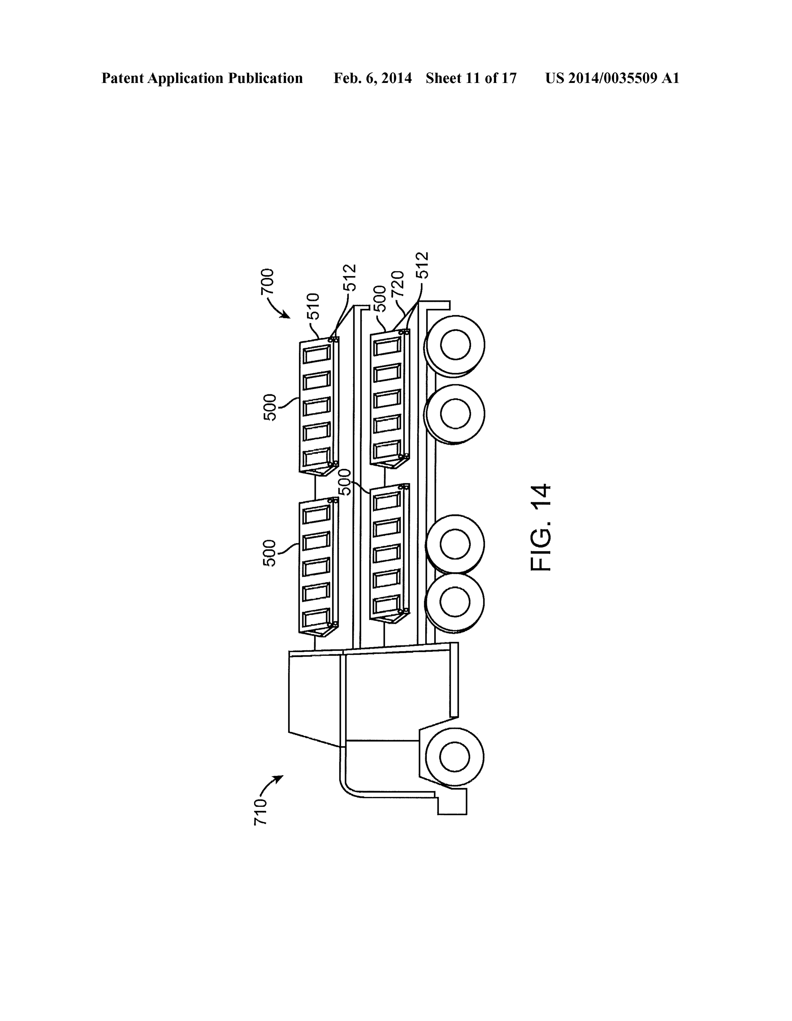
member; and a control system for lowering or retracting the 0032 FIG. 13 is a perspective view of an inflatable solar outer member. panel system, which is designed to float in a body of water in 0017. In accordance with a further exemplary embodi accordance with an exemplary embodiment. ment, an inflatable Solar panel Support, the Support com 0033 FIG. 14 is a perspective view of a system for trans prises: a lower section having an inlet and an outlet for filling porting a plurality of inflatable Solar panel systems. and draining water from the lower section; an upper section 0034 FIG. 15 is a perspective view of a windmill in the having an inlet and an outlet for inflating and deflating the form of a wind turbine in accordance with an exemplary upper section, and wherein the upper section has a horizontal embodiment.
base, and a pair of angled sides, which join together forming 0035 FIG. 16 is a perspective view of a windmill in the an angled Surface having at least one cavity, which receives a form of a wind turbine in accordance with another exemplary Solar panel; and a rechargeable battery, which receives a embodiment.
source of electrical power from the solar panel housed within the lower section and stores the source of electrical power. 0036 FIG. 17 is a perspective view of a windmill in the 0018. In accordance with another exemplary embodiment, form of a wind turbine inaccordance with a further exemplary embodiment.
wind turbine comprises: a base; a tower, the tower having a cavity therein, which houses a rechargeable battery, and one 0037 FIG. 18 is a perspective view of a wind and solar or more blades, which produce a source of electricity, which station in accordance with an exemplary embodiment. is stored in the rechargeable battery housed in the tower of the 0038 FIG. 19 is a perspective view of a wind and solar city wind turbine. in accordance with an exemplary embodiment. 0039 FIG.20 is a perspective view of a system for loading
BRIEF DESCRIPTION OF THE DRAWINGS and unloading of batteries stored within an electric vehicle in accordance with an exemplary embodiment.
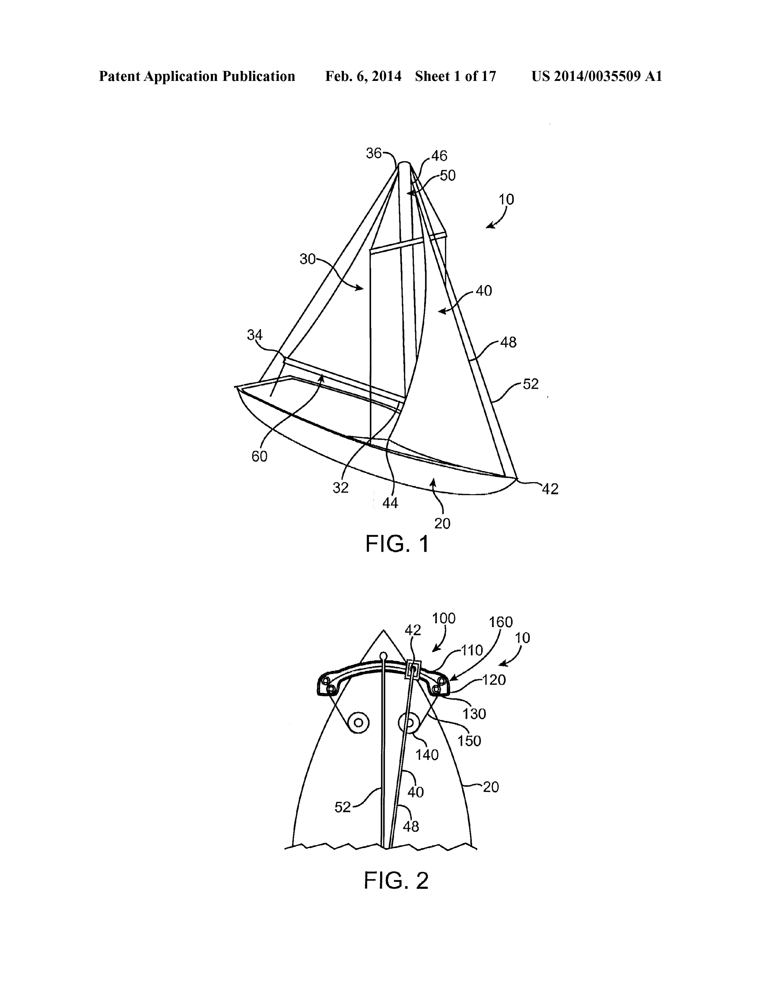
0019 FIG. 1 is a perspective view of a sailboat with a system and method of adjusting the location and position of DETAILED DESCRIPTION the foresail in accordance with one embodiment.
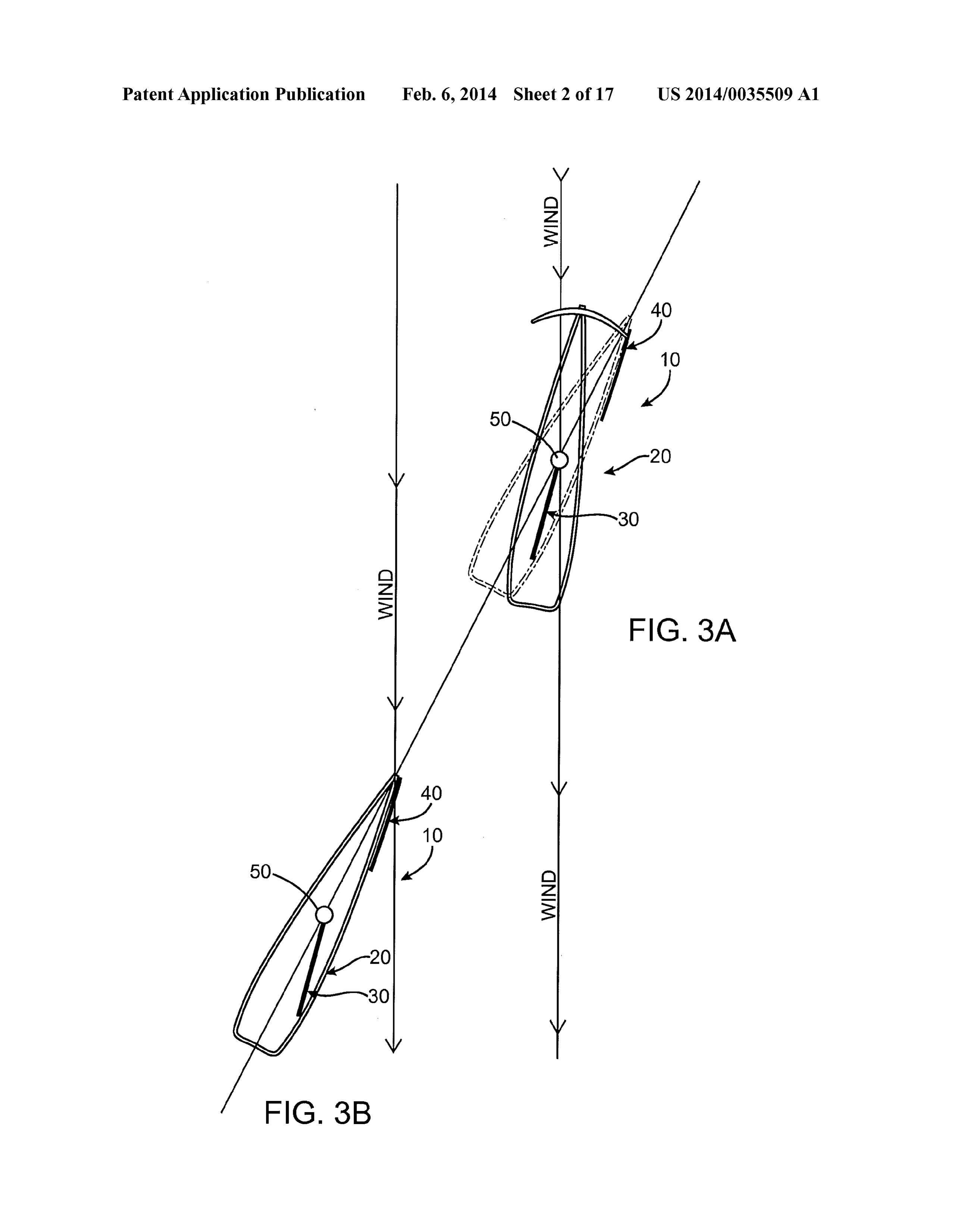
0020 FIG. 2 is a top view of the sailboat of FIG. 1 with a 0040. As described above, because of the design of the system and method of adjusting the location and position of sails, a sailboat (or boat) 10 can sail to windward, in a direc the foresail. tion no less than about 15 to 25 degrees from the wind, 0021 FIG. 3A is a schematic view of a sailboat in accor depending upon the design of the boat and the skill of the sailor. Headway directly upwind is achieved in a series of dance with one embodiment with a system and method of sequential maneuvers called tacks, in which the boat is first adjusting the location and position of the foresail in compari sailed windward with the wind over one side of the bow, and son with a sailboat without a system and method of adjusting then turned through the wind so that the wind comes over the the location and position of the headsail, jib, genoa, or spin other side of the bow. In each tack, some headway upwind is naker.
achieved even though the boat does not move directly into the 0022 FIG. 3B is a schematic view of a sailboat without a wind, and eventually the sailboat reaches an upwind objective system and method of adjusting the location and position of after sailing a Zig-Zag course covering a distance greater than the foresail. the straight line distance from the initial position to the 0023 FIG. 4 is a cross-sectional view of a portion of the upwind objective.
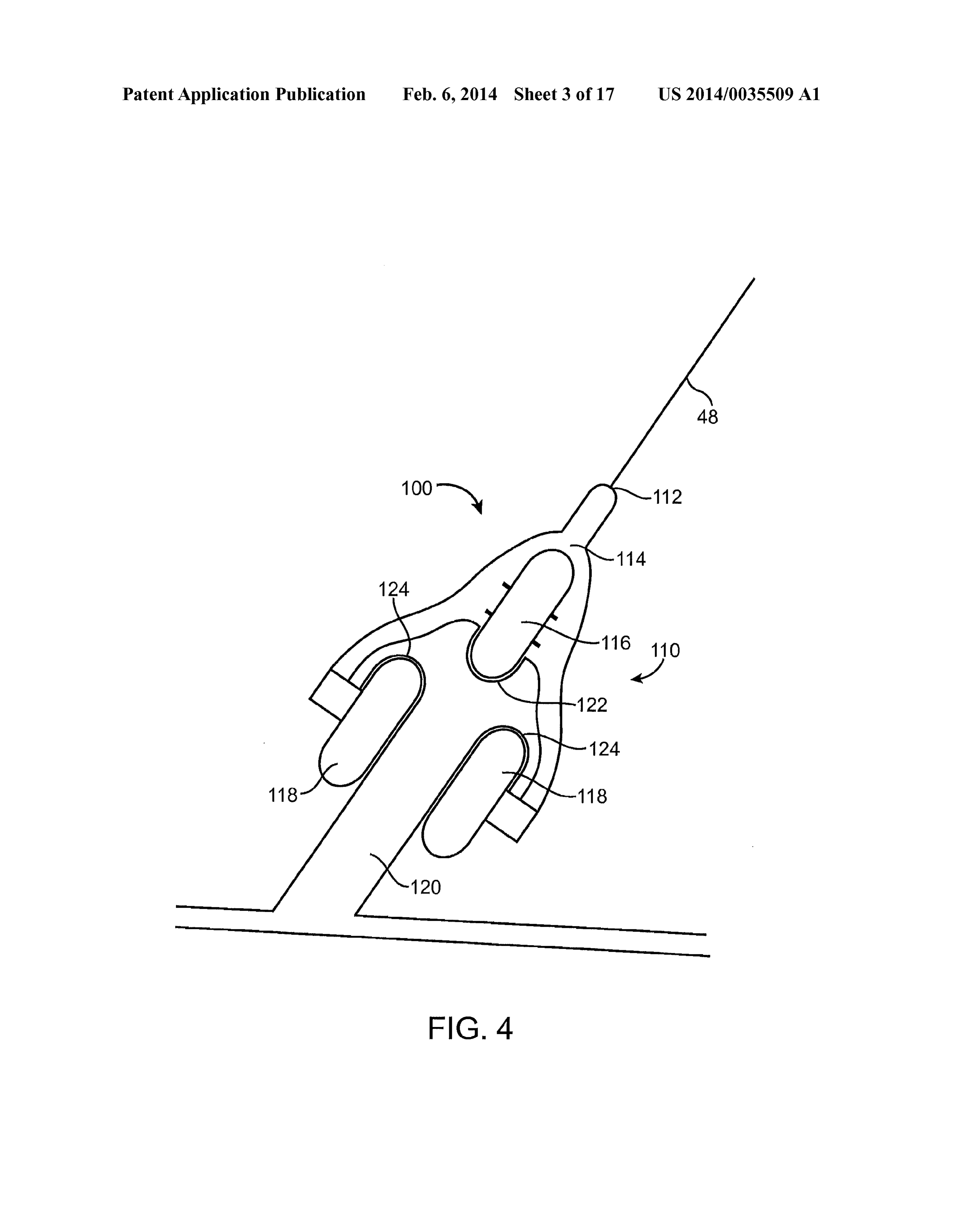
track system on a sailboat with a system and method of 0041. In addition, when a sailboat 10 sails to windward, adjusting the location and position of the foresail. the forces on the sails can be resolved into a thrust component 0024 FIG. 5 is a top view of a sailboat with a system and that moves the sailboat forwardly through the water and a drift method of adjusting the location and position of the foresail in component that pushes the sailboat sideways in a downwind accordance with another embodiment. direction. The sailboat 10 therefore moves in a net direction
Page 21
US 2014/0035509 A1 Feb. 6, 2014
that is forward, but also is slight downwind opposite to the net (the back corner of the sail 30) to the end of the boom. The line intended direction of movement. The sideways drift is called is pulled taut to the appropriate tension (to provide the desired leeway. shape to the foot), and then secured to a cleat on the boom 60. 0042. The downwardly projecting centerboard or keel of The mainsail 30 is also attached to the top 36 of the mast 50. the boat offers resistance to the leeway produced by the side The mainsail 30 extends aftward and is secured the whole ways sail force, but at least Some leeway remains. This leeway length of its edges to the mast 50 and to the boom 60 hung is being constantly accumulated, as there is a downwind from the mast 50.
movement as long as the sailboat is being sailed into the wind. 0046. The foresail 40, which is also known as a headsail, The leeway can significantly increase the time required for jib, genoa, or spinnaker is secured to the top 46 of the mast 50 the sailboat to sail from its downwind starting position to the and is typically secured to the bow 42 of the sailboat 10. upwind objective, as it forces the sailboat to sail much further Typically, the foresail 40 is secured along its leading edge to to make up for the accumulated sideways movement. a forestay 48 (strong wire) strung from the top 46 of the mast 0043 FIG. 1 shows a perspective view of a sailboat 10 to the bowsprit 42 on the bow (nose) of the boat. Alternatively, with a system and method of adjusting the location and of at the foresail 40 can be a genoa, which is a type of jib that is least one of the sails 40 of the sailboat 10, and more particu larger, and cut so that it is fuller thanan ordinary jib. It can also larly a system and method of adjusting the foresail 40 (or be appreciated that fore-and-aft sails can be switched from headsail, jib genoa, or spinnaker) in accordance with one one side of the sailboat 10 to the other, in order to alter the embodiment. As shown in FIG. 1, a sailboat 10 typically sailboats course. When the sailboat's stern crosses the wind, includes a hull 20 that sits in the water, a mast 50 extending this is calledjibing; when the bow crosses the wind, it is called upwardly from the hull 20, and at least one sail in the form of tacking. Tacking repeatedly from port to starboard and/or a mainsail 30 supported by the mast 50 and a boom 60, and an vice versa, called “beating, is done in order to allow the boat optional centerboard or keel 70 (FIG. 6) extending down to follow a course into the wind.
wardly from the hull 20 into the water. Typically, most sail 0047. It can be appreciated that a primary feature of a boats 10 also include a second sail 40 in the form of a foresail, properly designed sail is an amount of “draft, caused by jib, genoa, or spinnaker. The sails 30, 40 catch the wind and curvature of the surface of the sail. When the sail is oriented cause the hull 20 to move forwardly through the water. The into the wind, this curvature induces lift, much like the wing sailboat can also include a mainstay 52, which preferably of an airplane. Modern sails are manufactured with a combi extends from an upper portion of the mast 50 to the bow 42 of nation of broadseaming and non-stretch fabric. The former the sailboat 10. adds draft, while the latter allows the sail to keep a constant 0044. The use of the term "sailboat' 10 has a broad mean shape as the wind pressure increases. The draft of the sail can ing and can include yachts, (large sailboats) and Smaller ves be reduced in stronger winds by use of a Cunningham and sels of many configurations, which use wind as the primary outhaul, and also by increasing the downward pressure of the means of propulsion. Typically, Some of the variations other boom by use of a boom yang. A boom yang is a line or piston than size are hull configuration (monohull, catamaran, and system on a sailboat used to exert downward force on the trimaran), keel type full, fin wing, centerboard etc.), purpose boom and thus control the shape of the sail. In British English, (sport, racing, cruising), number and configuration of masts, it is known as a "kicking strap. The yang typically runs from and the sailplan. The most common sailboat 10 is the “sloop' the base of the mast 50 to a point about a third of the way out which features one mast50 and two sails, a mainsail 30 and a the boom 60. Due to the great force necessary to change the foresail 40 or jib, genoa, or spinnaker. This simple configu height of the boom 60 while a boat is under sail, a line based ration has been proven over time to be very efficient for boom yang usually includes some sort of a pulley System. sailing into the wind. The mainsail 30 is attached to the mast Hydraulic piston Vangs are used on larger sailboats and con 50 and the boom 60, which is a beam or spar capable of trolled by manual or electric hydraulic pumps. Swinging across the sailboat 10, depending on the direction of 0048 FIG. 2 shows a top view of the sailboat 10 of FIG. 1 the wind. Depending on the size and design of the foresail 40, with a system and method of adjusting the location and posi the foresail 40 is called a jib, genoa, or spinnaker. Although tion of the foresail 40. As described above, the foresail 40 is not common, a sloop or sailboat 10 can include two foresails typically attached to the bow 42 of the sailboat 10 via the from a single forestay 48 at one time (wing on wing). The forestay 48. In accordance with one embodiment, as shown in forestay 48 is a line or cable running from near the top of the FIG. 2, the foresail 40 can be attached to a track system 100. mast 50 to a point near the bow 42 (or front of the sailboat 10). The track system 100 is attached to the bow 42 of the boat 10 The forestay 48 is attached at either the top of the mast, or in and is configured to change the location or position of the fractional rigs between about /4 and /8 from the top of the foresail 40 and the forestay 48 relative to the hull 20 of the mast 50. The other end of the forestay 48 is attached to the boat 10 during a tacking maneuver.
stern or bow 42 of the boat 10. The forestay 48 can be made 0049 Tacking typically describes the position of a sail from stainless steel wire, a Solid stainless steel rod, a carbon boats bow with respect to the wind. For example, if the rod, a galvanized wire or natural fibers. vessel's bow is positioned so that the wind is blowing across 0045. As shown in FIG. 1, the mainsail 30 is attached to the starboard (right) side of the vessel, then the vessel is said the mast50 and the boom 60. The boom 60 is typically a metal to be on a starboardtack. If the wind is blowing across the port or wooden beam or spar, which is configured to stabilize the (left) side of the vessel, then the vessel is said to be on a port bottom of the mainsail 30. The boom 60 is attached to the tack. By definition, this is opposite to the side, which the mast 50 at a lower end 32 of the mast 50 and extends towards boom is carried, since it can be difficult when a boat is sailing the stern 43 (or back of the sailboat 10). An outhaul or line 34, downwind or nearly downwind from which side the wind is which is part of the running rigging of a sailboat 10, is used to coming. In addition, a sailing vessel on a starboard tack extend the mainsail 30, and control the shape of the curve of always has the right-of-way over another sailing vessel on the foot of the mainsail 30. The outhaul 34 runs from the clew "port tack” by both the rules of the road and racing rules.
Page 22
US 2014/0035509 A1 Feb. 6, 2014
0050. The track system 100 preferably includes a move preferably attached to an optional foresail track system 210, able track fixture 110, upon which the forestay 48 is securely which assists the foresail beam 220 in movement from side to fixed or attached, a fixed track 120 configured to receive the side. The forestay 48 (not shown) is preferably securely fixed track fixture 110, and a control system 130 for securing the or attached to the bow end 224 of the foresail beam 220. In location of the track fixture 110 within the track 120 relative addition, a series of lines 226 can be used to control the bow to the bow 42 of the boat 10. In accordance with one embodi end 224 of the foresail beam 220.
ment, the control system 130 for securing the location of the 0055. The system as shown in FIG. 5, the beam or spar track fixture 110 can include a winch 140, a flexible wire or system 200 can also include a control system 130 (not shown) rod 150 attached to the track fixture 110, and a guide system comprised of a winch 140, a flexible wire or rod 150 attached 160. The winch 140 is preferably a mechanical device that is to the track fixture 110, and a guide system 160. As described used to wind up the flexible wire or rod 150 (also called above, the winch 140 is preferably a mechanical device that is “cable'). In its simplest form, it consists of a spool and used to wind a wire rod or wire rope (also called “cable'). In attached crank. The spool can also be called the winch drum, its simplest form, it consists of a spool and attached crank. In that the winch 140 can include suitable gear assemblies and addition, the winch 150 can also include gear assemblies and can be powered by electric, hydraulic, pneumatic or internal can be powered by electric, hydraulic, pneumatic or internal combustion drives. In addition, the winch 150 can include a combustion drives. The winch 150 can also include a solenoid Solenoid brake and/or a mechanical brake or ratchet (not brake and/or a mechanical brake or ratchet, which prevents shown) that prevents the winch 150 from unwinding. the winch 150 from unwinding.
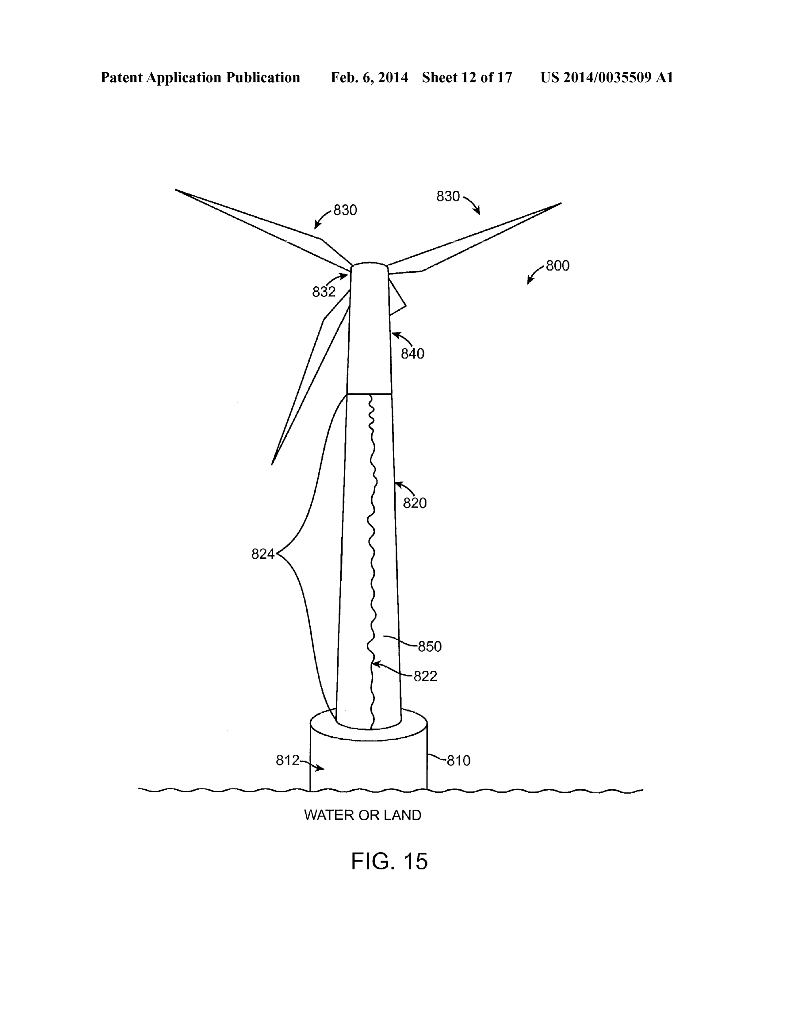
0051 FIG. 3A shows a schematic view of a sailboat 10 in 0056 FIG. 6 is a top view of a multi-hulled boat 300 with accordance with one embodiment with a system and method a system and method of adjusting the location and position of of adjusting the location and position of the foresail 40 in the foresail in accordance with a further embodiment. As comparison with a sailboat 10 without a system and method shown in FIG. 6, the multi-hulled boat 300 consists of two or of adjusting the location and position of the foresail 40. As more hulls 310, joined by a structure 320, the most basic shown in FIG. 3A, the control system 130 is configured to being a frame, or other Suitable structure, which spans from adjust or change the relative location of the foresail 40 to the one hull 310 to the other hull 310. The multi-hulled Sailboat bow 42 of the boat 10 during tacking maneuvers, such that the 300 can be sail and/or engine-powered. In accordance with an bow 42 of the boat 10 can sail into the wind more than if the exemplary embodiment, the two or more hulls 310 can have foresail 40 and forestay 48 is fixed to the bow of the boat 10. two differently shaped or sized hulls with lateral symmetry, or 0052 FIG. 3B shows a schematic view of a sailboat with alternatively, two or more hulls with longitudinal symmetry. out a system and method of adjusting the location and posi For example, a trimaran has a main hull 310 in the center and tion of the foresail. As shown in FIG.3B, a typical sailboat 10 symmetric stabilizing hulls 310 on either side. The boat 300 performs a tacking maneuver by sailing at an angle into the also includes one or more rudders 302 to guide the boat 300. wind. However, as shown in FIG. 3A, if the relative position 0057. It can be appreciated that a multi-hulled sailboat can of the foresail 40 to the bow 42 of the boat 10 is changed or have several advantages compared to a single-hull boat. For altered without change the relative position of the mainsail 30 example, by increasing the distance between the center of and foresail 40 to one another, the bow 42 of the boat 10 can gravity and the center of buoyancy provides higher stability sail more into the wind resulting in a shorter distance or path compared to boats with a single hull, which allows multi of travel for the sailboat during tacking. hulls to have narrower hulls and thus substantially less wave 0053 FIG. 4 shows a cross-sectional view of a portion of forming resistance, which in turn results in greater speed the track system 100 on a sailboat with a system and method without applying more effort. In the case of boats under sail, of adjusting the location and position of the foresail 40 in stability serves to hold the vessel upright against the sideways accordance with one embodiment. The track system 100 pref force of the wind on the sails. This stability is provided in erably includes a track fixture 110, and a fixed track 120. The multi-hulls by the weight of the boat itself, in contrast to foresail 40 (not shown) is attached to the forestay 48, which is mono-hull sailboat, which typically uses an underwater coun secured to the track fixture 110 at an upper end 112. As shown terweight, a ballasted keel for this purpose, especially on in FIG. 4, the track fixture 110 can include an upper end 112, larger sailboats. Multi-hull sailboats are typically much wider a main body 114, an upper wheel 116, and a pair of lower than the equivalent mono-hull, which allows them to carry no wheels 118. The fixed track 120 can include an upper groove ballast, and the reduced weight also makes them faster than 122 configured to receive the upper wheel 116 and a pair of mono-hulls under equivalent conditions. It can also be appre lower grooves 124 configured to receive the pair of lower ciated that multi-hulls typically will not sink or be abandoned wheels 118. The track fixture 110 moves from side to side if flooded, as opposed to ballasted mono-hulls who do indeed (starboard to port) on the fixed track 120 resulting in the sink when flooded. In addition, the comfort of more onboard relative position of the forestay 48 (and the foresail 40) to the accommodation space and more level boats under sail offer bow 42 of the boat 10 facing in a more windward direction Substantially improved conditions for crew and passengers, during tacking maneuvers. which contributes to the greatly increasing popularity of 0054 FIG. 5 shows a top view of a sailboat 10 with a multi-hull sailboats during the past few decades. system and method of adjusting the location and position of 0.058 As shown in FIG. 6, in accordance with an exem the foresail 40 in accordance with another embodiment. As plary embodiment, the multi-hulled boat 300 includes a mast shown in FIG. 5, a beam or spar system 200 comprised of a 330 and a track system 340. As described above, a leading foresail track system 210, a foresail beam 220, and a pivot edge of the foresail 40 is attached to the track system 330, member 230. The foresail beam 220 is attached to the pivot which extends from one hull 310 to another hull 310. The member 230 (or mast 50) at one end (mast end) 222 and the track system 340 preferably has an arc shape thereto, which other end (bow end) 224 of the foresail beam 220 moves from mirrors the movement of a leading edge of the foresail 40 side to side (starboard to port). The foresail beam 220 is during tacking maneuvers, such that the distance 342 from the
Page 23
US 2014/0035509 A1 Feb. 6, 2014
mast 330 to the track system 340 remains constant at all times. mechanical device that is used to wind a wire rod or wire rope In accordance with one embodiment, as shown in FIG. 6, the (also called “cable'). In its simplest form, it consists of a foresail 40 (FIG. 2) can be attached to the track system 340. spool and attached crank. In addition, the winch 150 can also The track system 340 is attached to each of the hulls 310 of the include gear assemblies and can be powered by electric, boat 300 and is configured to change the location or position hydraulic, pneumatic or internal combustion drives. The of the foresail 40 relative to the hulls 310 of the boat 300 winch 150 can also include a solenoid brake and/or a during a tacking maneuver. It can be appreciated that tacking mechanical brake or ratchet, which prevents the winch 150 typically describes the position of a sailboats bow with from unwinding.
respect to the wind. For example, if the vessel's bow is posi 0062 FIG. 8 is a top view of a multi-hulled boat 300 tioned so that the wind is blowing across the starboard (right) having one or more track systems 340 for adjusting the loca side of the vessel, then the vessel is said to be on a starboard tion and position of the foresail in accordance with a further tack. If the wind is blowing across the port (left) side of the embodiment. As shown in FIG. 8, the sailboat 300 includes a vessel, then the vessel is said to be on a port tack. It can be plurality (i.e., two or more) track system340, each of the track appreciated that by definition, this is opposite to the side, systems 340 configured to receive a foresail 40 (not shown). which the boom is carried, since it can be difficult when a boat Each of the track systems 340 extends from one hull 310 to is sailing downwind or nearly downwind from which side the another hull 310. The track system 340 preferably has an arc wind is coming. In addition, a sailing vessel on a starboard shape thereto, which mirrors the movement of a leading edge tack always has the right-of-way over another sailing vessel of the foresail 40 during tacking maneuvers, such that the on “port tack” by both the rules of the road and racing rules. distance 342 from the mast 330 to each of the track systems 0059. The track system 340 preferably includes a move 340 remains constant at all times. The track systems 340 are able track fixture 110 as shown in FIG. 2, upon which the attached to each of the hulls 310 of the boat 300 and are forestay 48 is securely fixed or attached, a fixed track 120 configured to change the location or position of the foresail 40 configured to receive the track fixture 110, and a control relative to the hulls 310 of the boat 300 during a tacking system 130 for securing the location of the track fixture 110 maneuver. In accordance with an exemplary embodiment, within the track 120 relative to the bow 42 of the boat 10. In each of the track systems 340 can also include a beam or spar accordance with one embodiment, the control system 130 for system 350 as shown in FIG. 8. If one or more beam or spar securing the location of the track fixture 110 can include a systems 350 (FIG. 8) are used, each of the foresail beams 352 winch 140, a flexible wire or rod 150 attached to the track are preferably at a different height relative to the deck 320 fixture 110, and a guide system 160. The winch 140 is pref and/or mast 330 so that the foresail beams 352 can move erably a mechanical device that is used to wind up the flexible freely. If the sailboat 300 has more than one foresail 40, wire or rod 150 (also called “cable'). In its simplest form, it depending on the conditions, one or more of the foresails 40 consists of a spool and attached crank. The spool can also be can be used at any time, such as during tacking maneuvers. called the winch drum. The winch 140 can include suitable 0063 FIG. 9 shows a cross-sectional view of a portion of gear assemblies and can be powered by electric, hydraulic, a sailboat 10 with an adjustable keel 400 in accordance with pneumatic or internal combustion drives. In addition, the another exemplary embodiment. As shown FIG. 9, the sail winch 150 can include a solenoid brake and/or a mechanical boat 10 with an extendable keel 400 includes a foil member brake or ratchet (not shown) that prevents the winch 150 from 450 (shown in a perspective view), an extendable outer mem unwinding. ber 470 and a fixed inner member 480. The foil member 450 0060 FIG. 7 shows a top view of a multi-hull boat 300 is attached to the extendable outer member 470 and uses the with a system and method of adjusting the location and posi forward motion of the boat 10 to generate lift to counter the tion of the foresail 40 in accordance with another embodi lateral force from the sails (i.e., mainsail 30 and foresail 40). ment. As shown in FIG. 7, a beam or spar system 350 com Sailboats 10 typically have much larger keels than non-sail prised of a foresail track system 340, a foresail beam 352, and ing hulls. In addition, the keel 400 is made of a heavy material a pivot member 354. The foresail beam 352 is attached to the to provide ballast to stabilize the sailboat 10. Accordingly, it pivot member 354 (or mast 330) at one end (mast end) 356 would be desirable to have the ability to adjust the depth or and the other end (bow end) 358 of the foresail beam 352 length of the keel 400, which provides a righting moment of moves from side to side (starboard to port). The foresail beam the sailboat 10 during tacking. Thus, the sailboat 10 will be 352 is preferably attached to a lower portion of the mast 330 quicker and will be faster during sailing competitions and/or and extends approximately horizontal to a deck 304 of the races. In addition, the perpendicular distance from weight to boat 300. The foresail (not shown) includes a leading edge (or pivot is increased. In addition, with the use of an extendable clew or free end), which is attached to the bow end 358 of the keel 400, a larger righting moment can be produced. The foresail beam 352, a trailing edge, and a top edge (or head), extendable keel 400 also provides for easier transportation of which is generally attached to an upper portion of the mast the sailboat 10 by retracting the keel 400 and allows for the 330. sailboat 10 to sail in shallower water with the keel 400 0061. In accordance with another exemplary embodiment, retracted.
the foresail beam 352 is preferably attached to an optional 0064. In accordance with another exemplary embodiment, foresail track system 340, which assists the foresail beam 352 the extendable outer member 410 is positioned on an exterior in movement from side to side. The forestay 48 (not shown) is or outer portion of the fixed inner member 420. The outer preferably securely fixed or attached to the bow end 358 of the member 410 has outer wall 412, which surrounds the fixed foresail beam 352. The system as shown in FIG. 7, the beam inner member 420, and can be raised and/or lower as needed. or spar system 350 can also include a control system 130 as A suitable fit between the outer member 410 and the inner shown in FIG. 2 comprised of a winch 140, a flexible wire or member 420 preferably exists such that the sailboat 10 does rod 150 attached to the track fixture 110, and a guide system not take water on and the fit is suitable to withstand the 160. As described above, the winch 140 is preferably a corrosive environment that most sailboats 10 typically
Page 24
US 2014/0035509 A1 Feb. 6, 2014
encounter. As shown in FIG. 9, the extendable outer member support 500, the lower section 512 is filled with a liquid or 410 is in a raised or retracted position, which surrounds the medium, Such as water, and the upper section 514 is prefer fixed inner member 420. Upon lowering or extending the ably inflated with a gas, Such as air. In accordance with an outer member 410, the outer member extends further into the embodiment, handles (not shown) can be provided on the water or away from the hull 20 of the sailboat 10. lower and/or upper sections 512,514. Lifting the handles lifts 0065. In accordance with one embodiment, the adjustable the upper section 514 and pre-inflates the upper section 514 keel 400 also includes a control system (not shown), which with air.
includes a mechanical system, which controls the position of (0071. In accordance with an embodiment, water fills at the outer member 410 relative to the fixed inner member 420, least a portion of the lower section 512. The filling of the which in turn controls the depth of the adjustable keel 400. In lower section 512 with water can increase the air pressure accordance with one embodiment, the control system con within the upper section 514. In addition, the increased air sists of a spool or drum and an attached crank. The control pressure helps to shape the upper section 514. In accordance system also preferably includes suitable gear assemblies and/ with one embodiment, the lower section 512 has vents (not or can be powered by electric, hydraulic, pneumatic or inter shown) in fluid communication with the upper section 514. nal combustion drives. The control system can also include a The vents release excess pressure from the lower section 512. solenoid brake and/or a mechanical brake that prevents the The vents also guide air from the lower section 512 into the system from unwinding and/or releasing from a fixed posi upper section 514 as the liquid or medium (e.g., water) fills tion. the pre-shaped lower section 512. This increases the air pres 0066. As shown in FIG. 9, the keel 400 also preferably sure in the upper section 514 and enables the upper section includes a foil member 450 having a winged foil 452 (or 514 to become rigid to shape and support the lower section underwater wing) positioned on a distal end 402 of the keel 512. Air pressure also shapes the upper section 514 to inhibit 400. The foil member 450 with a winged foil 452 provides lift the solar panels 538 (FIG. 12) from being displaced from the in a largely upwardly direction (rather than laterally, as for a support 500.
leeway reducing keel) to reduce the wetted area of the hull 20 0072. As shown in FIG. 12, the inflatable solar panel Sup and thence its drag as the sailboat 10 moves forwardly. port 500 includes at least one cavity 530, which is adapted to 0067 FIG. 10 shows a cross-sectional view of a sailboat receive a solar panel 538. The solar panel 538 is preferably an 10 with an adjustable keel 400 in an extended position with a array of solar-thermal panels or photovoltaic (PV) modules, winged keel 450 in accordance with another embodiment. As or other Suitable Solar panel, which converts Sunlight into an shown in FIG. 10, the sailboat 10 has an extendable keel 400, energy source. The at least one cavity 530 includes a base 534 which includes a winged keel 450 having a foil member 452, and a plurality of vertical orangular edges 532, which forms an extendable outer member 410 and a fixed inner member an outer perimeter of the cavity 530. In accordance with one 420. The winged keel 450 is attached to the extendable outer embodiment, a pair of elastic straps 536 can be added to each member 410 and uses the forward motion of the boat 10 to of the cavities 530 and/or alternatively, a pair of elastic straps generate lift to counter the lateral force from the sails (i.e., 536 can extend across the angled sections 516, 518 of the mainsail 30 and foresail 40). As shown in FIG. 10, the outer upper section 514 to provide a means to retain the Solar panel wall 412 of the extendable outer member 410 is connected to 538 within each of the cavities 530. the keel 400 and moves upward when the keel 400 is raised (0073 FIG. 13 is a perspective view of an inflatable solar and moves downward when the keel 400 is lowered. panel system 600, which is designed to floatin a body of water 0068 FIG. 11 is a perspective view of an inflatable solar 650 in accordance with another exemplary embodiment. The panel support 500 in accordance with another exemplary inflatable solar panel system 600 includes one or more solar embodiment. As shown in FIG. 11, the inflatable solar panel panel supports 500, and an anchor (e.g., weight) 610, which system 500 includes an inflatable support structure 510 com secures the system 600 to an area within the body of water prised of a pair of inflatable and/or water-filled sections 512, (not shown). The system 600 can also be equipped with a light 514. In accordance with an embodiment, the lower section 620 and/or warning system 630 in the form of a siren, a horn 512 includes an inlet 540, and an outlet 542 for filling and and/or a bell provides warning to oncoming ships and/or draining the water from the lower section 512. In an alterna boaters of the existence of the inflatable solar panel system tive embodiment, the upper section 514 has an inlet 550 and 600. The light 620 and warning system 630 are preferably an outlet 552 for inflation and deflation of the upper section positioned above and/or on an upper surface orportion 570 of 514. The inlets 540, 550 and the outlets 542,552 are prefer the one or more solar panel supports 500. As shown in FIG. ably one-way valves in the form of a relief valve or other 13, the light 620 and warning system 630 is located above the Suitable valving arrangement. one or more solar panel supports 500, however, the light 620 0069. In accordance with one embodiment, the lower sec and warning system 630 can be located on an upper Surface or tion 512 is preferably water fillable and holds water to weight portion 570 of the support structure 510. Alternatively, the the support 500. The upper section 514 is preferably air fin system 600 can be designed without an anchor or weight 610 able and normally holds air to shape the support structure 510. for use on land and/or structures wherein the system 600 will The upper section 514 preferably has a horizontal base 520, not float and/or drift away from a desired location. and a pair of angled sides 516, 518, which join together 0074. In accordance with an exemplary embodiment, the forming an angled surface 522 having at least one cavity 530, inflatable solar panel system 600 is preferably deployed in a which receives a Solar panel (not shown). In accordance with body of water 650, which is traveled by boats, ship and the one embodiment, the solar panel is preferably any suitable like. The body of water can be any navigable waterway, river, panel or array of smaller panels, which converts Sunlight into steam, lake and/or ocean. The one or more solar panels Sup a source of energy or energy source. ports 500 are preferably filled with air and/or water, and fixed 0070. The solar panel support 500 is preferably portable or attached to an area within the body of water via the anchor and compresses and folds for easy transport. To set up the 610. The lower section 512 is preferably water finable and
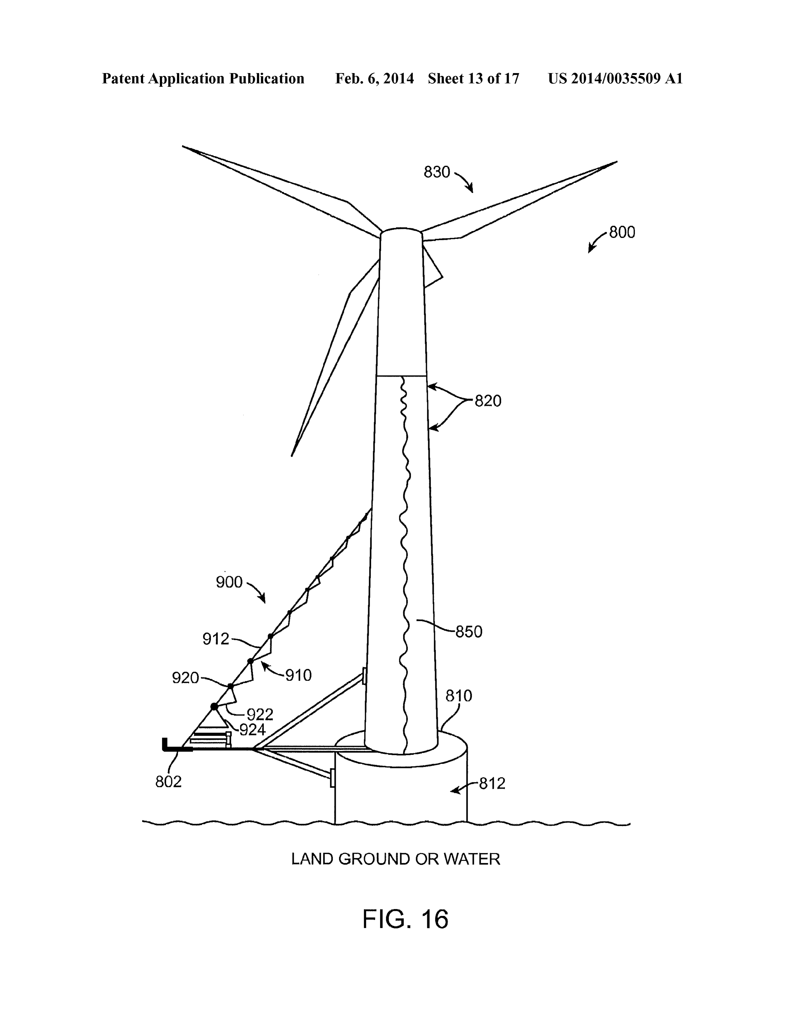
Page 25
US 2014/0035509 A1 Feb. 6, 2014
normally holds water to weight the support 500. However, in with an exemplary embodiment, the liquid medium is prefer accordance with an alternative embodiment, the lower section ably non-toxic. The lower section 512 also preferably 512 can be configured as a rechargeable battery 560, which includes a collector, which conducts the charge to the outside preferably includes one or more cells, each cell housing pref of the battery and through a load. erably a pair of electrodes—one positive, one negative, which 0079. During use, when a load completes the circuit are immersed in a liquid (e.g., water) containing electrically between the two terminals, the water-based battery produces charged particles, or ions. In accordance with an exemplary electricity through a series of electromagnetic reactions embodiment, the liquid is preferably water in the form of between the anode, cathode and electrolyte. The anode expe fresh and/or salt water, and the ions for example, can be riences an oxidation reaction in which two or more ions sodium and chlorine. However, the lower section 512 can (electrically charged atoms or molecules) from the electrolyte include other suitable liquids and/or materials, which can be combine with the anode, producing a compound and releas used to form rechargeable batteries within the lower section ing one or more electrons. At the same time, the cathode goes 512, can be used. through a reduction reaction in which the cathode Substance, 0075. In accordance with an exemplary embodiment, the ions and free electrons also combine to form compounds. The liquid is preferably water in the form of fresh, salt water reaction in the anode creates electrons, and the reaction in the and/or a combination of fresh and salt water, Thus, in addi cathode absorbs them, such that the net product is electricity. tion, to providing ballast to the support 510, the lower section 0080 FIG. 14 is a perspective view of a system 700 for 512 acts a water-based rechargeable battery 560 for storing transporting a plurality of inflatable solar panel systems 500. electricity generated by the solar panels 538, which is then As shown in FIG. 14, the system 700 includes a track 710, stored within the at least one cavity 530 of the support struc which has a flatbed and/or deck 720 for transporting one or ture 510. In accordance with an exemplary embodiment, the more support structures 510. The plurality of support struc at least one cavity 530 comprises a plurality of cavities. tures 510 are preferably placedon the flatbed and/or deck 720 0076. In accordance with an exemplary embodiment, the in a partially filled manner or a fully filled manner, which lower section 512 includes one or more cells (or cavities), and prevents the support structures 510 from sliding around and preferably a plurality of cells (or cavities), which each house allows the structures 510 can be delivered to the site in a two electrodes and water in the form of fresh and/or saltwater. complete or ready to use manner. In accordance with an The water is preferably added to the lower section 512 upon exemplary embodiment, no foundation and/or additional placement of the support structure 510 at the desired location. straps or tie downs are needed since the weight of the lower For example, in accordance with an embodiment, the support section 512 secures each of the Support structures 510 to the structure 510 can be transported to a remote location and the flatbed and/or deck 720 of the truck during transportation of lower section 512 can be filled with water, which secures the the structures 510. Alternatively, if the support structures 510 support structure 512 to the desired location and forms a do not contain water within the lower section 512 and/or water-based rechargeable battery having one or more electro additional precautions are needed due to the terrain and/or chemical cells that can store the electrical power or electricity distance in which the structures 510 are to be transported, the generated by the Solar panels. structures can be tied down or secured to the truck 710 as 0077. In accordance with an exemplary embodiment, the needed with ties and other Suitable securing measures (not lower section 512 preferably has material therein, which can shown).
provide a storage source (i.e., rechargeable battery, which I0081. In accordance with another exemplary embodiment includes one or more electrochemical cells that convert stored as shown in FIG. 15, a wind turbine (or windmill) 800 can be chemical energy into electrical energy) for the one or more used to generate a source of electrical energy, and which can solar panel supports 500. The lower section 512 is preferably be stored on site until the generated energy is needed later by made of a flexible metal material, and/or plastic or plastic like adding a storage system or battery within the base 810 or material that can house the materials, which form the battery. tower 820 of the wind turbine (or windmill)800. Windmills or Each of the one or more solar panel supports 500 are prefer wind turbines 800 generally have either a vertical or a hori ably pre-wired and includes all the materials for a water Zontal axis, and are built with a propeller-type rotor on a based battery include a cathode, which connects to the posi horizontal axis (i.e., a horizontal main shaft) in order that they tive terminal, and an anode, which connects to the negative may face directly into a wind. Most horizontal axis turbines terminal. In accordance with an exemplary embodiment, a include two or three-blades 830, although, windmills or wind liquid medium in the form of fresh, Salt and/or a combination turbines 800 can have between one to five or more blades 830. of fresh and salt water is all that is needed to complete the The rotor converts the linear motion of the wind into rota rechargeable battery. During storage of the Source of electri tional energy that can be used to drive a generator. cal power and/or electricity generated by the Solar panel, a 0082 In accordance with an alternative embodiment, the positive active material is oxidized, producing electrons, and wind turbine 800 is a vertical axis wind turbine (“VAWT) the negative material is reduced, consuming electrons. These (not shown), Vertical-axis wind turbines are typically of a electrons constitute the current flow in the external circuit. long axis type, allowing large columns of air to be harnessed. The liquid medium (or electrolyte) may serve as a simple The two main types of VAWTs are the Savonius turbine, buffer for ion flow between the electrodes. which is a high speed, low torque turbine, and the Darrieus 0078. As described above, the cathode and anode form the turbine, which is a low speed, high torque turbine. The Dar electrode, which are preferably separated via a barrier, which rieus turbine resembles an eggbeater, where two vertically prevents the electrodes from making contact with one oriented blades revolve around a vertical shaft. The Darrieus another, and allowing electrical charges to flow freely models use an airfoil design so that a wind turbine airfoil between the cathode and anode. The medium (or electrolyte), works in the same way as an airplane wing so that an airfoil preferably in the form of a liquid medium allows the electric has a flat side and a curved side. The result of airpassing over charges to flow between the cathode and anode. In accordance the two sides is a force known as “lift.” One advantage to the
Page 26
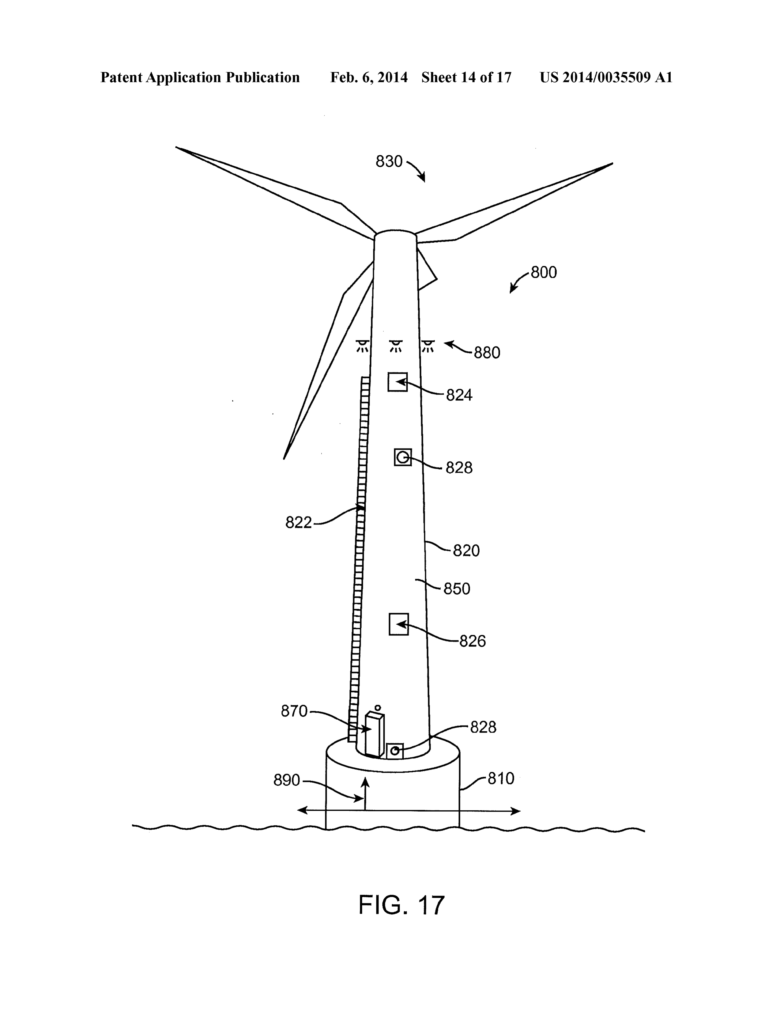
US 2014/0035509 A1 Feb. 6, 2014
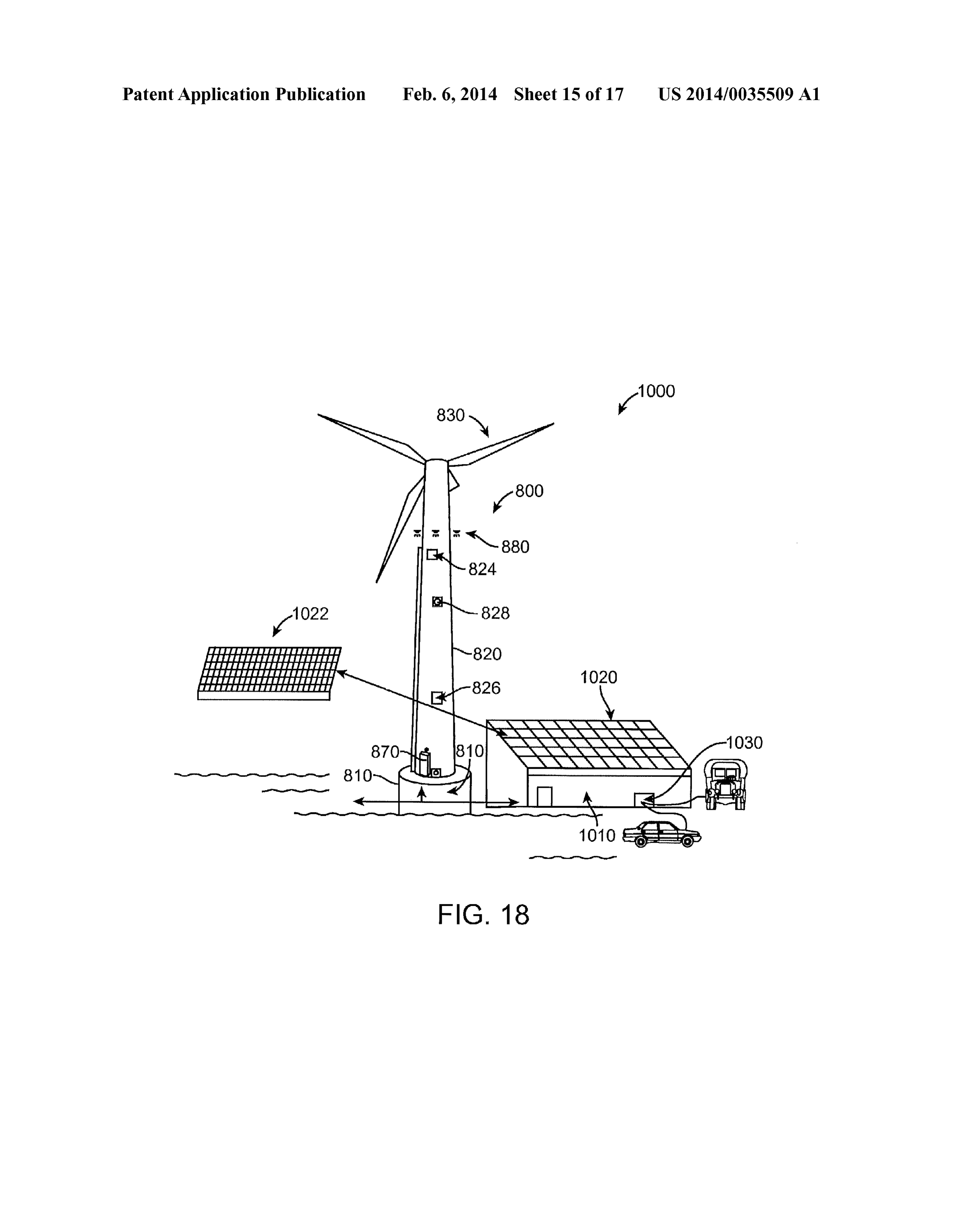
Vertical axis wind turbines is that the gearbox and generators off the machine at about 55 mph. In most cases, wind turbines can be placed close to the ground, which makes these com 800 do not operate at wind speeds above about 55 mph ponents easier to service and repair, and that VAWTs do not because of the potential damage to the windmills that can need to be pointed into the wind. occur with high-speed winds.
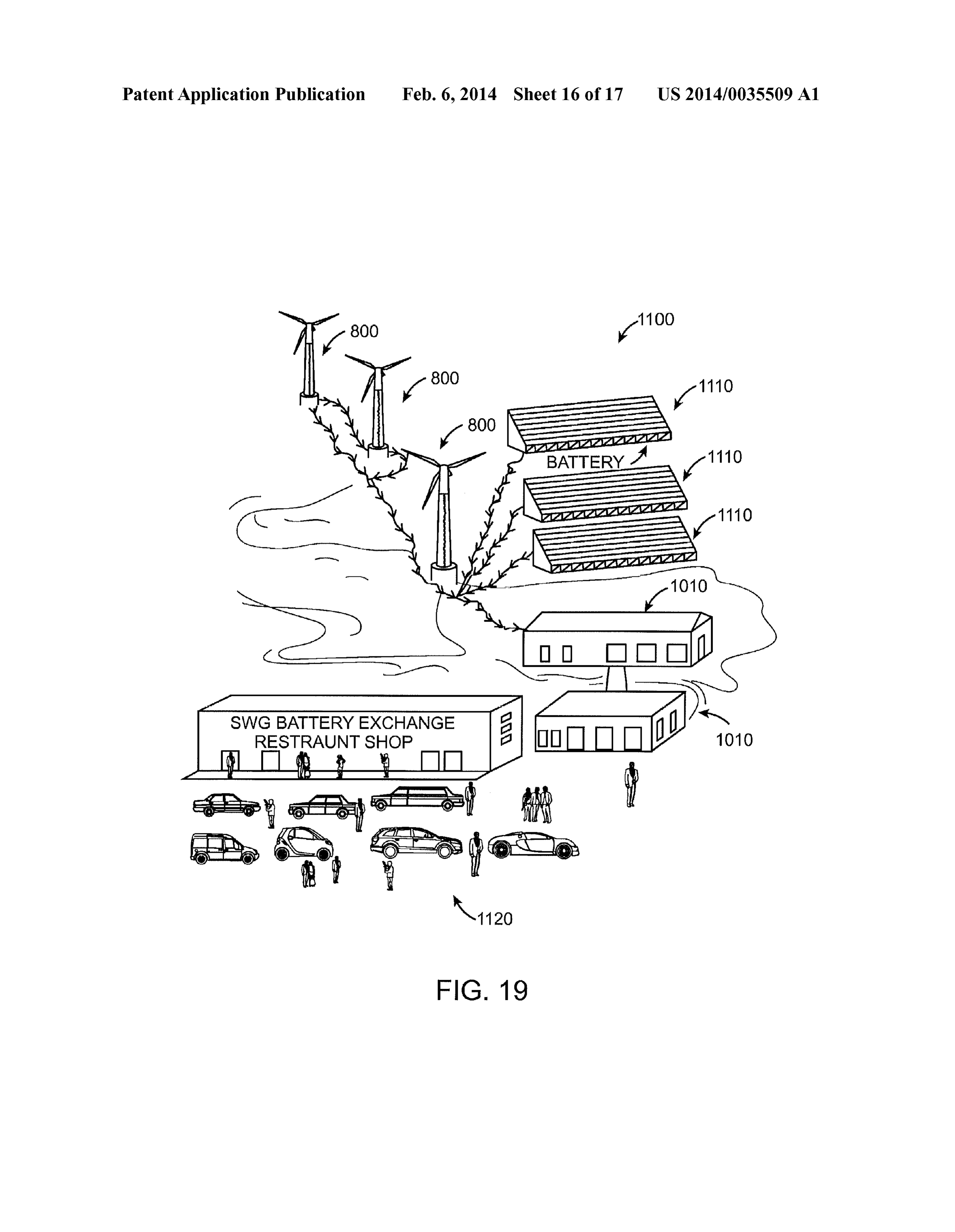
I0083 FIG. 15 is a perspective view of a windmill in the 0087. As shown in FIG. 15, the wind turbine 800 has a forin of a horizontal wind turbine 800. Typically, windmills plurality of blades 830, and more preferably three blades 830, and/or wind turbines utilize wind created by the uneven heat which are connected to a hub (not shown), which in combi ing of the atmosphere by the Sun, the irregularities of the nation with the blades 830 forms the rotor 832. In accordance earth's Surface, and rotation of the earth to generate a source with an exemplary embodiment, the wind turbine 800 of alternative or Solar energy. In addition, wind flow patterns includes a high-speed shaft drives the generator, and a low can be modified by the earth's terrain, bodies of water, and speed shaft, which is turned by a rotor at about 30 to 60 vegetation. In most windmills or wind turbines 800, the wind rotations per minute. An "upwind turbine, is so-called turns the blades, which spin a shaft, which connects to a because it operates facing into the wind. Alternatively, other generator and makes electricity. In most uses, a plurality of turbines can be designed to run "downwind.” facing away wind turbines generates electricity for the utility grid. The from the wind. The wind turbine 800 also preferably includes electricity is sent through transmission and distribution lines a wind Vane (not shown), which measures wind direction and to homes, businesses, Schools, and so on. As described above, communicates with the yaw drive to orient the turbine prop most modern wind turbines fall into two basic groups: the erly with respect to the wind. The yaw drive is used to keep the horizontal-axis variety, as shown in FIGS. 15-18, and the rotor facing into the wind as the wind direction changes for Vertical-axis design (not shown), like the eggbeater-style Dar upwind turbines, which face into the wind, and which is rieus model, named after its French inventor. powered with a yaw motor. The wind turbine or windmill also 0084 As shown in FIG. 15, horizontal-axis wind turbines preferably includes an anemometer, which measures the wind 800 typically either have two or three blades. These two or speed and transmits wind speed data to a controller. For three-bladed wind turbines operate “upwind, with the blades emergencies, the wind turbine 800 is preferably equipped facing into the wind. In accordance with an exemplary with a disc brake, which can be applied mechanically, elec embodiment, it would be desirable to have a wind turbine 800 trically to stop the rotor.
with an on-site water based rechargeable battery that can be I0088. As shown in FIG. 15, the tower 820 has a cavity (or used in connection with photovoltaic systems for use in hollow-out space or core) 822, which is configured to hold a remote, off-grid locations, where electricity is not available liquid medium, such as water. In accordance with an exem and/or connections to an utility grid is not available. plary embodiment, in remote locations, wherein water Stor 0085. As shown in FIG. 15, a windmill 800 in the form of age is limited, the cavity within the tower 820 can be config a wind turbine includes a base 810 having a tower 820 ured to hold and/or store water. The cavity 822 preferably has thereon, and one or more blades 830. The base 810 is prefer a height 824 thereto, which can vary depending on the loca ably made of steel and/or concrete to support the tower 820 tion of the wind turbine 800 and intended use and needs of the and the one or more blades 830. The tower 820 is preferably storage portion of the turbine 800. In addition, the base 810 made from tubular steel (shown here), concrete, or steel lat can include a cavity 812 therein, which can also be used to tice. Because wind speed increases with height, taller towers store or hold a liquid medium, Such as water. 820 enable turbines 800 to capture more energy and generate I0089. In accordance with another exemplary embodiment, more electricity. As shown in FIG. 15, the wind turbine 800 the cavity 812, 822 is configured as a rechargeable battery preferably has either two or three blades 830, and wind blow 850, which preferably includes one or more cells, each of the ing over the blades 830 causes the blades 830 to “lift” and one or more cells housing a pair of electrodes—one positive, rotate. In accordance with an exemplary embodiment, the one negative, which are immersed in a liquid (e.g., water) blades 830 are preferably turned, or pitched, out of the wind containing electrically charged particles, or ions. In accor to control the rotor speed and keep the rotor from turning in dance with an exemplary embodiment, the liquid is prefer winds that are too high or too low to produce electricity. ably water in the form of fresh or salt water, and the ions for I0086. The windmill 800 also preferably includes anacelle example, can be sodium and chlorine. However, the cavity 840, which sits atop the tower and contains the gearbox, 812, 822 can include other suitable liquids and/or materials, low-speed and high-speed shafts, generator, controller, and which can be used to form a rechargeable battery within the brake. The gearbox houses the gears, which connect the low cavity 812, 822 of the base 810 or tower 820. The base 810 or speed shaft to the high-speed shaft. The low-speed shaft to tower 820 housing the water-based rechargeable battery 850 high-speed shaft provides for an increase of the rotational acts as a storage unit, which stores the generated electrical speeds from approximately 30 to 60 rotations per minute power, which can be transferred via wires to a power grid (rpm) to upwards of approximately 1000 to 1800 rpm, which and/or saved for use by devices connected to the wind turbine is the rotational speed required by most generators to produce 800. As described above in connection with FIG. 13, the wind electricity. A power line is preferably attached to the genera turbine 800 houses a water-based rechargeable battery 850, tor and can be positioned either within the tower 820 or which includes all the materials for a water-based battery alternatively, can be run on an exterior surface of the tower including a cathode, which connects to the positive terminal, 820. Since gear boxes are often costly and heavy, in accor and an anode, which connects to the negative terminal. In dance with an exemplary embodiment, a direct-drive genera accordance with an exemplary embodiment, a liquid medium tor that operates at a lower rotational speed and does not in the form of fresh, salt and/or a combination of fresh and salt require a gear box can also be used in place of a traditional water completes the rechargeable battery 850. During storage gear box. The wind turbine 800 also preferably includes a of the source of electrical power and/or electricity generated controller, which aids with the startup of the wind turbine 800 by the rotating blades 830 of the wind turbine 800, a positive at wind speeds of about 8 to 16 miles per hour (mph) and shuts active material is oxidized, producing electrons, and the nega
Page 27
US 2014/0035509 A1 Feb. 6, 2014
tive material is reduced, consuming electrons. These elec tower 820. The plurality of solar panels 910 are preferably trons constitute the current flow in the external circuit. The attached or fixed to the wire and/or line 912 by a connector liquid medium (or electrolyte) serves as a buffer for ion flow 920 such as a connecting rod or hook. The units 900 also between the electrodes. The cathode and anode form the includes a system for the unfolding the plurality of solar electrode, which are preferably separated via a barrier, which panels 910 and extending the connector 920 (i.e., connecting prevents the electrodes from making contact with one rod or hook) upward towards the windmill prwind turbine another, and allowing electrical charges to flow freely 8OO.
between the cathode and anode. The medium (or electrolyte), 0094. In accordance with an exemplary embodiment, preferably in the form of a liquid medium allows the electric when not in use, the solar panels 910 can be retracted and charges to flow between the cathode and anode. In accordance stored on the ground or deck of the windmill 800. The system with an exemplary embodiment, the liquid medium is prefer for extension and retraction of the solar panels 910 is prefer ably non-toxic. The wind turbine 800 can include a collector, ably a Suitable mechanical device (not shown) that can extend which conducts the charge to the outside of the battery and and retract the plurality of solar panels 910 as needed. In through a load. accordance with an exemplary embodiment, the mechanical 0090. During use, when a load completes the circuit device preferably includes a spool (or winch drum) and between the two terminals, the water-based battery produces attached crank. The mechanical device or winch can be pow electricity through a series of electromagnetic reactions ered by electric, hydraulic, pneumatic or internal combustion between the anode, cathode and electrolyte. The anode expe drives, and includes a Solenoid brake and/or a mechanical riences an oxidation reaction in which two or more ions brake or ratchet that prevents it from unwinding. (electrically charged atoms or molecules) from the electrolyte (0095. The one or more solar units 900 are preferably con combine with the anode, producing a compound and releas trolled by a computer system (not shown), which receives ing one or more electrons. At the same time, the cathode goes information from a sensor and/or other device of the current through a reduction reaction in which the cathode Substance, weather conditions and/or needs of the wind turbine 800, to ions and free electrons also combine to form compounds. The control the use of the panels (i.e., extension and retraction of reaction in the anode creates electrons, and the reaction in the the panels as needed). In addition, the plurality of solar panels cathode absorbs them, such that the net product is electricity. 910 can be positioned on a rotatable member, which rotates 0091. In addition, if the storage capacity of the battery with the relative position of the sun to maximize the produc housed within the base cavity 812, or tower cavity 822 is full, tion of electrical power from the plurality of solar panels 910. the excess generated electrical power (overage) from the I0096. A protective cover (not shown) can be placed over wind turbine 800 can be sent to other wind turbines 800 the stack of solar panels 910 during storage thereof or when having storage capacity or sold and/or transferred to a larger the solar panels 910 are not in use. As shown in FIG.16, a pair storage area or grid. In accordance with an exemplary of solar panels 922,924 are attached to each preferably via the embodiment, a trickle charger (not shown) can monitor the connector 920, which preferably is a connecting rod or hook, battery 850 of to ascertain whether the battery storage within and can include a pair of hinges, such that the plurality of solar the wind turbine 800 is operating properly. panels 910 can be stored in a stack (i.e., Z-fold) when not in 0092 FIG. 16 is a perspective view of a windmill 800 in use. As shown in FIG. 16, the panel system 900 comprises a the form of a wind turbine in accordance with another exem pair of solar panels 922,924 having a hinge between to allow plary embodiment. As shown in FIG.16, the wind turbine 800 the plurality of panels 910 to be stacked when not in use. The include one or more solar units 900 in the form a plurality of plurality of panels 922,924 can also include at least one edge solar panels 910, which are attached to the tower 820 of the member (not shown), which assists with the alignment of the wind turbine 800. The plurality of solar panels 910 are pref solar panels 910 during use. The at least one edge member is erably connected to the same power grid (not shown) as the preferably a wire, a hook attaching the outer edge of the Solar wind turbine 800 and in combination with the wind turbine panels to one another or other Suitable method ofattaching the 800 produce a source of electrical power, which can be fed panels to one another.
into the power grid and/or stored for later use within the wind (0097 FIG. 17 is a perspective view of a windmill in the turbine and/or separate storage facility. The solar panels 910 form of a wind turbine 800 in accordance with a further are preferably any suitable panel or array of Smaller panels, exemplary embodiment. As shown in FIG. 17, the tower 820 which converts Sunlight into an energy source. In accordance of the wind turbine 800 is equipped with an exterior ladder with an exemplary embodiment, any solar panel 910 can be (outside the tower) 822 and/or an interior ladder (inside the used including flat solar thermal collector, such as a Solar hot tower) (not shown), which can be used to access the outside water or air panel used to heat water, air, or otherwise collect and inside of the tower portion 820 of the wind turbine 800 as Solar thermal energy, or any photovoltaic module, which is an needed. The tower 820 is also preferably equipped with one or assembly of solar cells used to generate electricity. The solar more watertight doors and/or opening 824, 826, which are panels 910 are preferably flat, and can be various heights and positioned on an upper portion and a lower portion of the widths. The solar panels 910 can be slightly curved or of a tower 820, respectively. The one or more watertight doors suitable flexible design. In addition, each solar panel 910 can and/or openings 824, 826, provide access to the tower cavity be comprised of an array of Solar-thermal panels or photovol 822 as need for cleaning and/or other necessary maintenance. taic (PV) modules, which are be connected either in parallel In addition, the tower 820 is also preferably fitted with one or or series depending upon the design objective. more pump station fittings or connections 828, wherein liquid 0093. In accordance with one embodiment, the one or preferably in the form of water can be added and/or removed more solar units 900 preferably include a plurality of solar from an interior portion or cavity 822 of the tower 820 as panels 910, which are attached to the tower 820 via a wire needed. The tower 820 also includes an instrument control and/or line 912, which extends from a lower portion or deck panel and system 870, which controls the wind turbine and/or 802 of the windmill or wind turbine 800 upwards along the battery portion of the wind turbine, which is house within the
Page 28
US 2014/0035509 A1 Feb. 6, 2014
tower 820. The instrument control panel and system 870 can solar power station 1100, which provides and/or services include a combined control panel and system for both the electric vehicles and the like 1120. In accordance with wind turbine 800 and the battery portion 850, or alternatively, another exemplary embodiment, the generated electrical cur two or more instrument control panels and systems 870 can be rent or power can be transmitted through an insulated water used, which control the wind turbine 800 and the battery 850 line (not shown).
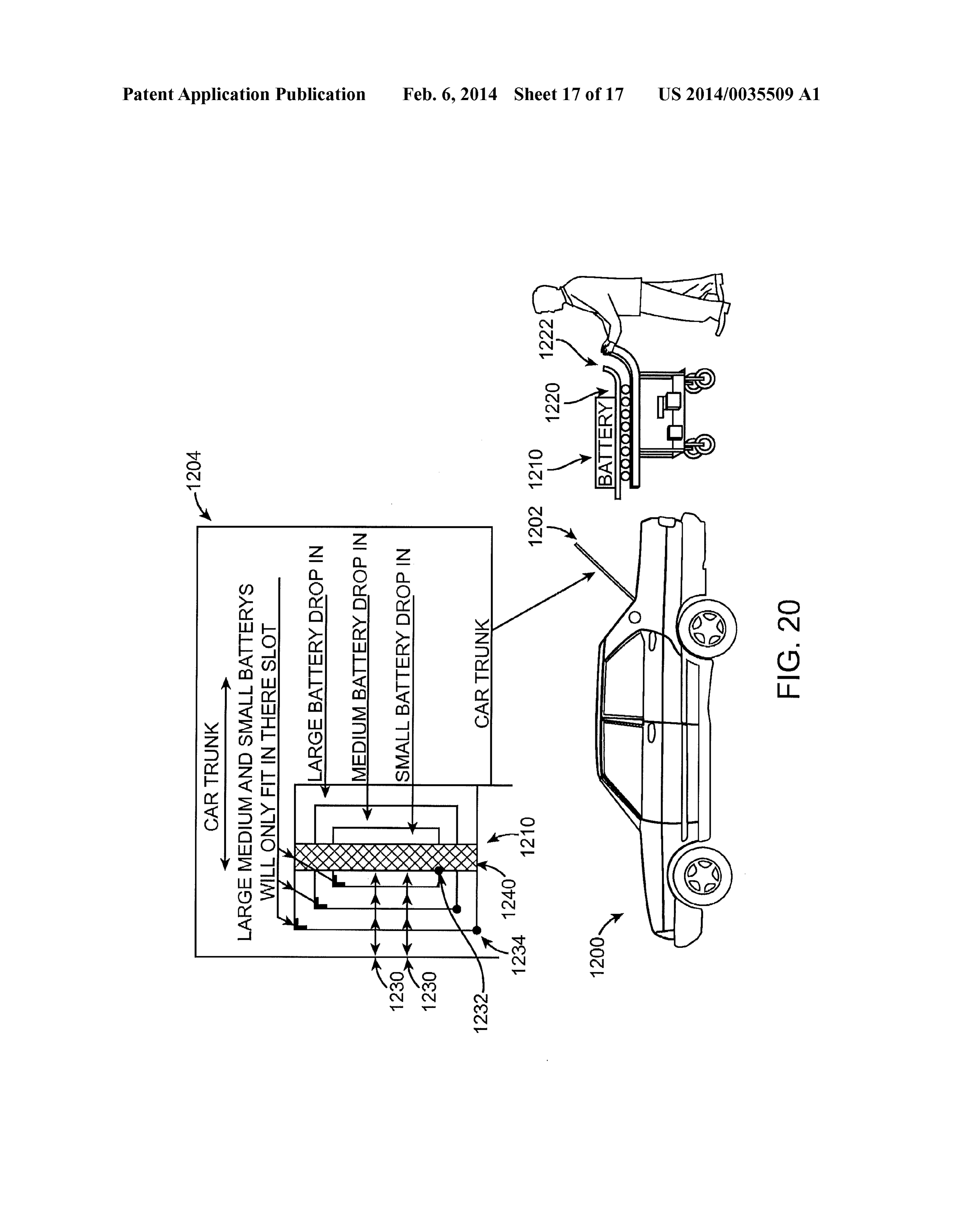
separately. In addition, the tower 820 has a ground system 0101 FIG.20 is a perspective view of a system for loading 880, which controls the electrical charge generated by the and unloading of batteries, which power an electric vehicle or wind turbine and stored within the tower 820, The wind turbine 800 is attached to a power grid and/or other wind truck 1200 in accordance with an exemplary embodiment. As turbine via a cable 890, which transmits electrical current shown in FIG. 20, an electrical vehicle or truck 1200 prefer and/or power as needed and/or requested. ably includes a removable or replaceable source of electrical power or battery 1210, which powers the vehicle or truck 0098 FIG. 18 is a perspective view of a wind and solar 1200. In. accordance with an exemplary embodiment, the station 1000 in accordance with an exemplary embodiment. trunk 1202 of the vehicle 1200 has a housing 1204, which can As shown in FIG. 18, the windmill station 1000 includes at receive a source of power or battery 1210, which can have one least one wind turbine 800, at least one battery housing (or or more sizes. For example, the housing 1204 can be config electrical storage facility) 1010, which includes optional solar ured to receive a source of power and/or battery 1210 having panels 1020. The optional solar panels 1020 are preferably one or more sizes, e.g., Small, medium and/or large, or any comprised of a plurality of Solar arrays, which convert Sun other Suitable destination of size, e.g., a certain number of light into electricity or electrical power. The optional solar Volts. In accordance with an exemplary embodiment, the panels 1020 are preferably placed on the roof or deck of the housing 1204 has a generally rectangular shape, which electrical storage facility 1010. In addition, optionally one or receives the source of electrical power and/or battery 1210 more solar support structures 510 as shown in FIGS. 11 and having a corresponding shape (e.g., rectangular). 12 can be used. The wind and solar station 1000 preferably is located in remote locations such that electric vehicles and the 0102. As shown in FIG. 20, the housing 1204 has a plu like can receive a source of electrical power as needed via a rality of electrical connections 1230, which are configured to plug-in station 1030. The plug-in station 1030 is preferably receive a corresponding electrical connection (not shown) on attached and/or at least connected to the battery housing a lower surface of the source of electrical power or battery 1010. The battery housing 1010 preferably stores a source of 1210. After the source of electrical power or battery is placed electrical power generated from the one or more wind tur within the housing 1204, in accordance with an exemplary bines 800. In accordance with an exemplary embodiment, the embodiment, a pin or other like device 1232 can be inserted optional solar panels 1020 provide power in the form of into a corresponding opening or hole 1234, which secures the electrical charge so as to maintain a constant or sufficient source of electrical power or battery 1210 within the housing storage levels within the battery housing 1010 to meet the 1204. In accordance with an exemplary embodiment, the needs of the Surround area and/or demands of any intercon housing 1204 includes a center slot 1240, which guides the nected municipalities and/or other users of the stored electri source of electrical power or battery 1210 in place. The center cal power. slot 1240 is preferably configured that sources of electrical 0099 FIG. 19 is a perspective view of a wind and solar city power or batteries 1210 of different sizes can universally be 1100 in accordance with an exemplary embodiment. As placed within the housing 1204. In addition, the size of the shown in FIG. 19, the wind and solar city 1100 include one or source of electrical power or battery 1210 can determine the more wind turbines 800, one or more battery housings 1010, distance (e.g., number of miles) that the vehicle can travel and one or more optional solarpanels arrays 1110. Each of the before needing to be charged. In accordance with an exem one or more wind turbines 800 and the one or more optional plary embodiment, each of the sources of electrical power or solar panel arrays 1110 are preferably connected to each other batteries 1210 can universally be exchanged at all or most any and Supply either alternating current (AC) or direct current wind and/or Solar city 1100 having charging capabilities as (DC) to the one or more battery housings 1010. The one or described herein.
more wind turbines 800 generate a source of electricity, 0103) In accordance with another exemplary embodiment, which is stored within the wind turbine 800 and/or alterna the source of power or battery 1210 is manually loaded into tively, the source of electricity is transferred to the one or the trunk of the vehicle 1200 using a battery loading device more battery housings 1010. In accordance with an exem 1220 in the form of a hand cart 1222, which includes a manual plary embodiment, the direct current, or alternatively, alter system for loading and unloading of the source of power or nating current can be provided to a battery Supply warehouse battery into the trunk of the vehicle 1200. The loading device 1110. The battery supply warehouse 1110 provides a 1220 is configured such that when the source of electrical rechargeable battery or battery source 1210 (FIG. 20), which power (i.e., battery)) is in place, a handle is pullbackwards or station personnel remove and/or replace within an electric towards the operator, which advances the battery 1210 into vehicle 1200. In addition, the battery supply warehouse 1110 the trunk of the vehicle 1200 and the center slot 1240 within can be used to charge and/or recharge used batteries. the housing 1204. The loading device 1220 preferably 0100. In accordance with an alternative embodiment, includes one or more bearings, which allows the battery 1210 rather than supply a source of direct current (DC), an alter into the trunk of the vehicle. The loading device 1220 is also nating current (AC) can be used if the system requires. In preferably designed to remove a source of electrical power or addition, if one or more of the battery housings has excess or battery from the trunk 1202 of the vehicle or truck in a similar extra electrical power, the excess or extra electrical power can manner by pulling backwards on the handle of the loading be supplied to a power grid, e.g., a municipal electric com device 1220, which dislodges the battery 1210 from the hous pany. As shown in FIG. 19, each of the battery stations 1110 ing 1204 and places the battery 1210 on the deck of the is preferably attaches or connects with at least one wind and loading device 1220.
Page 29
US 2014/0035509 A1 Feb. 6, 2014
0104. The loading device 1220 is preferably configured to 38. The wind turbine of claim 37, wherein the first and handle two or more batteries 1210, (i.e., “out with old in with second liquid mediums are fresh water. the new') such that the operator of the loading device 1220 39. The wind turbine of claim 37, wherein the cavities needs to make only one trip to each of the vehicles 1200. For within the base and the tower are configured as a rechargeable example, in accordance with an exemplary embodiment, the batteries, each of the rechargeable batteries includes one or loading unit 1220 can be configured to house one battery 1210 more cells, each of the one or more cells having a positive on each side thereof. In addition, the loading device 1220 is electrode and a negative electrode, which is immersed in the preferably configured to load and unload batteries 1210 into first and the second liquid mediums containing electrically any type of vehicle and/or truck 1200. charged particles and/or ions.
0105. It will be understood that the foregoing description 40. The wind turbine of claim 39, comprising: is of the preferred embodiments, and is, therefore, merely a power grid in electrical communication with the wind representative of the article and methods of manufacturing turbine.
the same. It can be appreciated that many variations and modifications of the different embodiments in light of the 41. The wind turbine of claim 39, wherein the first and above teachings will be readily apparent to those skilled in the second liquid mediums are fresh water and/or salt water. art. Accordingly, the exemplary embodiments, as well as 42. The wind turbine of claim 40, comprising: alternative embodiments, may be made without departing at least one wind turbine having a base, a tower, the tower from the spirit and scope of the articles and methods as set having a cavity therein, which houses a rechargeable forth in the attached claims. battery, and one or more blades, which produce a source 1.-27. (canceled) of electricity, which is stored in the rechargeable battery 28. A wind turbine comprising: housed in the tower of the wind turbine; a base; an electrical connector configured to transfer the source of a tower, the tower having a cavity therein, which houses a electricity stored in the wind turbine and/or the at least rechargeable battery; and one wind turbine from the wind turbineto the at least one one or more blades, which produce a source of electricity, wind turbine and/or the at least one wind turbine to the which is stored in the rechargeable battery housed in the wind turbine.
tower of the wind turbine. 43. The wind turbine of claim 36, wherein the first liquid 29. The wind turbine of claim 28, wherein the rechargeable medium is fresh water.
battery includes two electrodes, which are immersed in a 44. The wind turbine of claim37, wherein the second liquid liquid containing electrically charged particles. medium is fresh water.
30. The wind turbine of claim 28, further comprising a 45. The wind turbine of claim 36, comprising: generator, which is connected to the one or more blades and a rechargeable battery housed within the tower, the produces a source of electricity, which is stored within the rechargeable battery having one or more cells, each of rechargeable battery.
31. The wind turbine of claim 28, further comprising a the one or more cells having a positive electrode and a nacelle, which sits atop the tower and contains a gearbox, negative electrode, which is immersed in the first liquid low- and high-speed shafts, a generator, a controller, and/or a medium containing electrically charged particles and/or brake. ions;
32. The wind turbine of claim 28, further comprising one or a generator, which is connected to the one or more blades more Solar units in the form a plurality of Solar panels, which and produces a source of electricity, which is stored are attached to the tower of the wind turbine via wire and/or within the rechargeable battery; and line, which extends from a lower portion of the wind turbine a nacelle, which sits atop the tower and contains a gearbox, upwards along the tower. low- and high-speed shafts, a controller, and/or a brake. 33. The wind turbine of claim 32, wherein the plurality of 46. A system for removing a removable source of electrical Solar panels includes a system for the unfolding the plurality power from an electric Vehicle, comprising: of Solar panels and extending the plurality of Solar panels a vehicle having a housing configured to receive a source of upward towards an upper portion of the wind turbine, and electrical power, the housing having a central slot con wherein not in use, the Solar panels can be retracted and stored figured to guide Sources of electrical power having dif in a Z-fold stack. ferent sizes into the housing, each of the different sizes 34. The wind turbine of claim 28 further comprising one or of the sources of electrical power corresponding to a more wind turbines and at least one least one battery housing, distance the electric vehicle can travel, and wherein the which stores the source of electrical power generated by the source of electrical power has a plurality of electrical one or more wind turbines. connections configured to electrically engage a plurality 35. The wind turbine of claim 34, further comprising a of electrical connections within the housing. plurality of Solar arrays, which are placed on a roof and/or 47. The system of claim 46, comprising: deck of the at least one battery housing. a battery loading device configured to manually load and 36. A wind turbine comprising: unload the one or more source electrical sources into the a base; vehicle, wherein the battery loading device includes a a tower, the tower having a cavity therein configured to handle, which is configured to dislodge the Source of hold a first liquid medium; and electrical power from the vehicle and place the source of one or more blades, which produce a source of electricity. electrical power on the battery loading device, and con 37. The wind turbine of claim 36, wherein the base includes figured to advance the source of electrical power from a cavity configured to hold a second liquid medium. the battery loading device onto the plurality of electrical
Page 30
Drawing sheet — no readable text.

Provenance
- Collection
- Patents citing this work
- Pages
- 30
- Method
- pdftotext (the PDF's own text layer) + pdftoppm 300dpi page scans
- Patent office record
- patents.google.com →
- Source
- Google Patents citing-documents table
- Assignee
- Bradford G. Baruh
- Inventors
- Bradford G. Baruh
- Published
- 2014-02-06
- Transcribed from
- patentimages.storage.googleapis.com →