patent · US20130014728A1
Heat engine and power generation system using the heat engine
17 January 2013
Page 1 — bibliographic record
(19) United States (12) Patent Application Publication (10) Pub. No.: US 2013/0014728A1
Ozaki et al. (43) Pub. Date: Jan. 17, 2013 (54) HEAT ENGINE AND POWER GENERATION Publication Classification
SYSTEMUSING THE HEAT ENGINE
(75) Inventors: Yoriyasu Ozaki, Kyoto (JP); Masakatsu F02P 5/145 (2006.01) Uchiyama, Kyoto (JP) FO2B 47/02 (2006.01) (52) U.S. Cl. .................. 123/25 A: 123/445; 123/406.19
(73) Assignee: MASA INTERNATIONAL CORP. The present invention has a problem aiming to provide a heat Kyoto (JP) engine that emits neither carbon dioxide nor nitrogen oxide and is capable of achieving a simplified structure, and another (21) Appl. No.: 13/636,848 problem aiming to provide a power generation system using the heat engine.
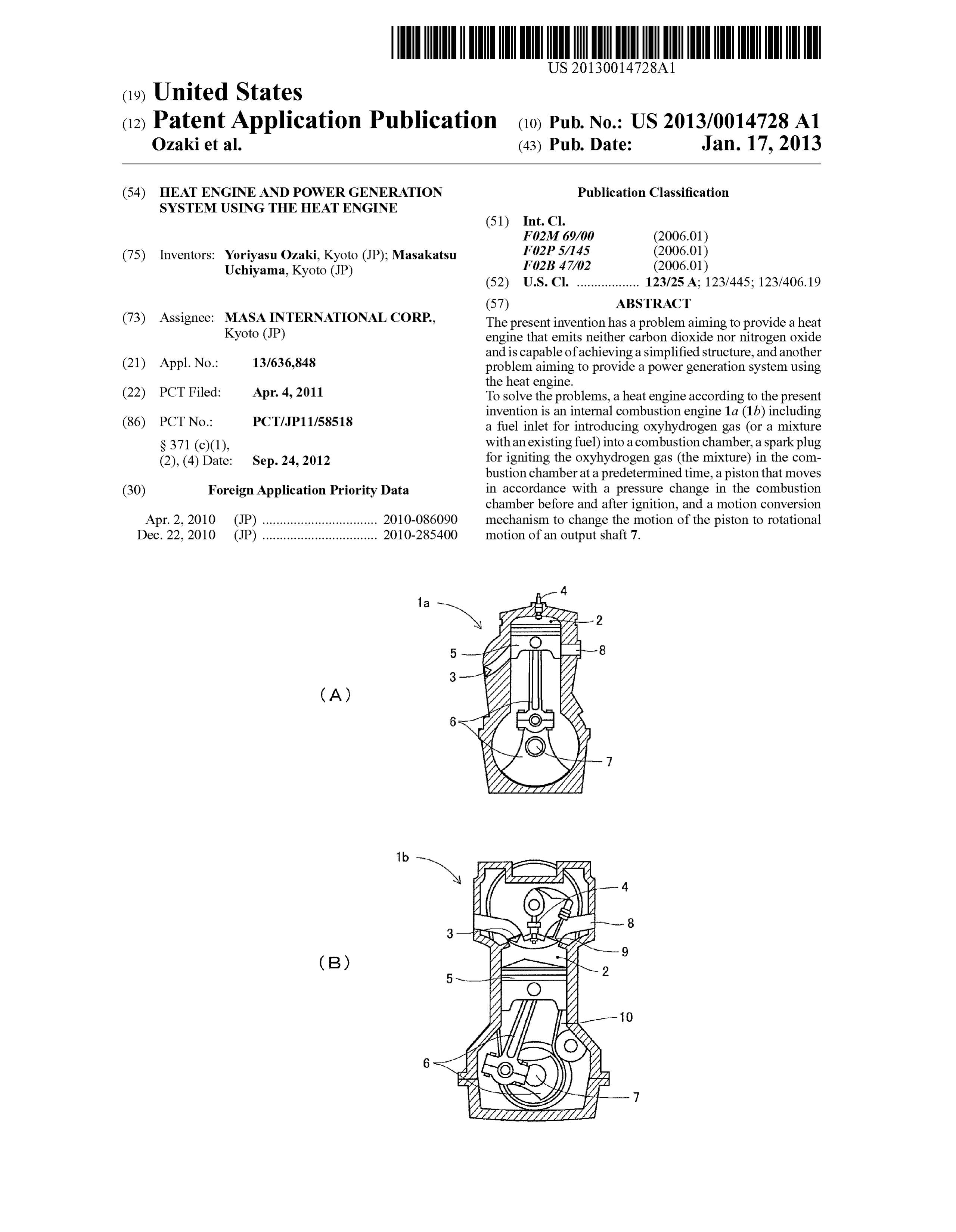
(22) PCT Filed: Apr. 4, 2011 To solve the problems, a heat engine according to the present invention is an internal combustion engine 1a (1b) including (86). PCT No.: PCT/P11158518 a fuel inlet for introducing oxyhydrogen gas (or a mixture S371 (c)(1), with an existing fuel) into a combustion chamber, a sparkplug (2), (4) Date: Sep. 24, 2012 for igniting the oxyhydrogen gas (the mixture) in the com bustion chamber at a predetermined time, a piston that moves (30) Foreign Application Priority Data in accordance with a pressure change in the combustion chamber before and after ignition, and a motion conversion
Apr. 2, 2010 (JP) ................................. 2010-086090 mechanism to change the motion of the piston to rotational Dec. 22, 2010 (JP) ................................. 2010-2854OO motion of an output shaft 7.
Page 2
Drawing sheet — no readable text.
Page 3
Drawing sheet — no readable text.
Page 4
Patent Application Publication Jan. 17, 2013 Sheet 3 of 6 US 2013/001.4728A1
NERNAL COMBUSTION
OXYHYDROGEN GAS
OXYHYDROGEN GAS
PRODUCING DEVICE
INTERNAL COMBUSTION
MIXENG FOSSIL-DERVED
OXYHYDROGEN GAS
OXYHYDROGEN GAS
PRODUCING DEVICE 2O
NJECON DEVICE
INTERNA. COMBUSTION
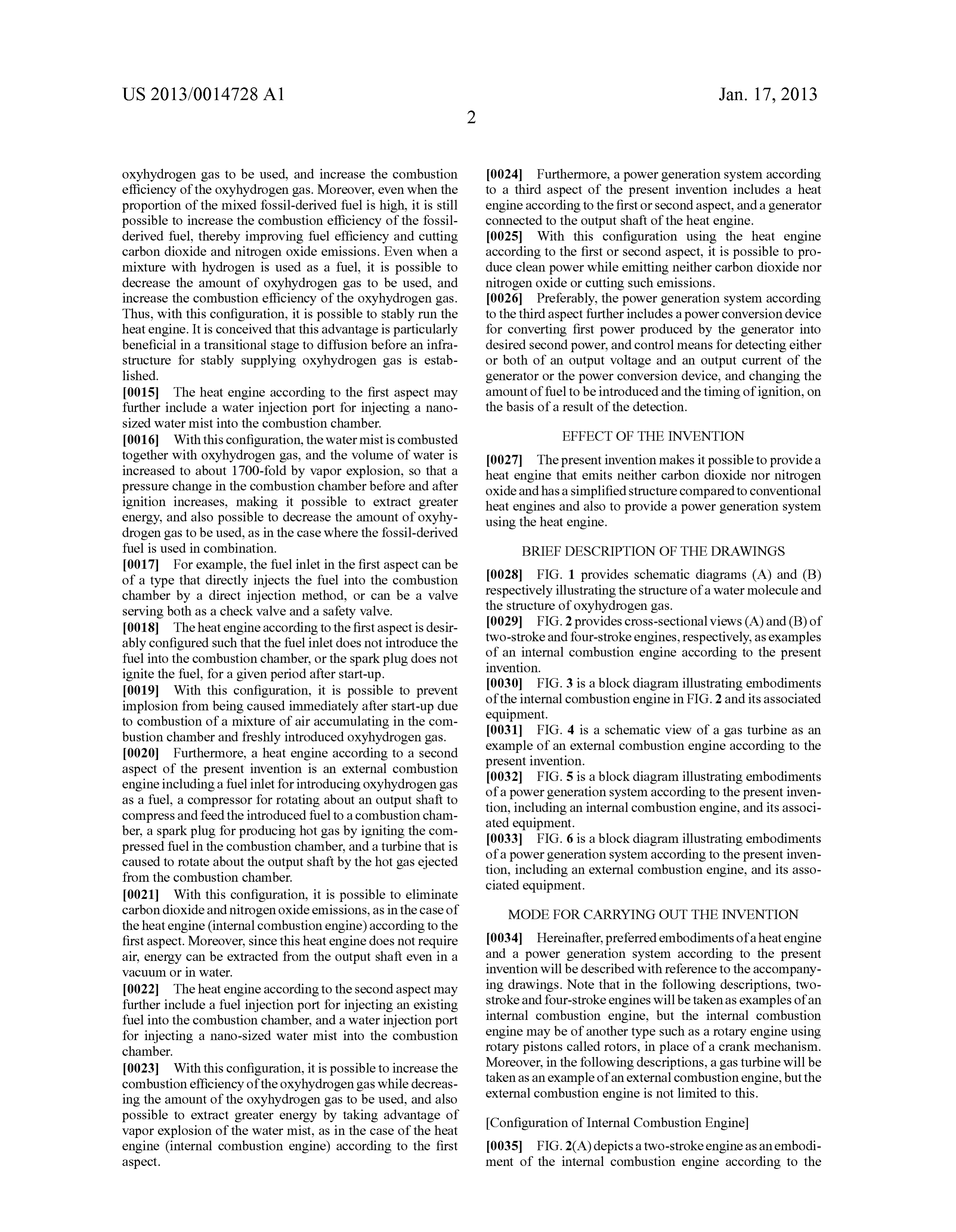
ENGINE
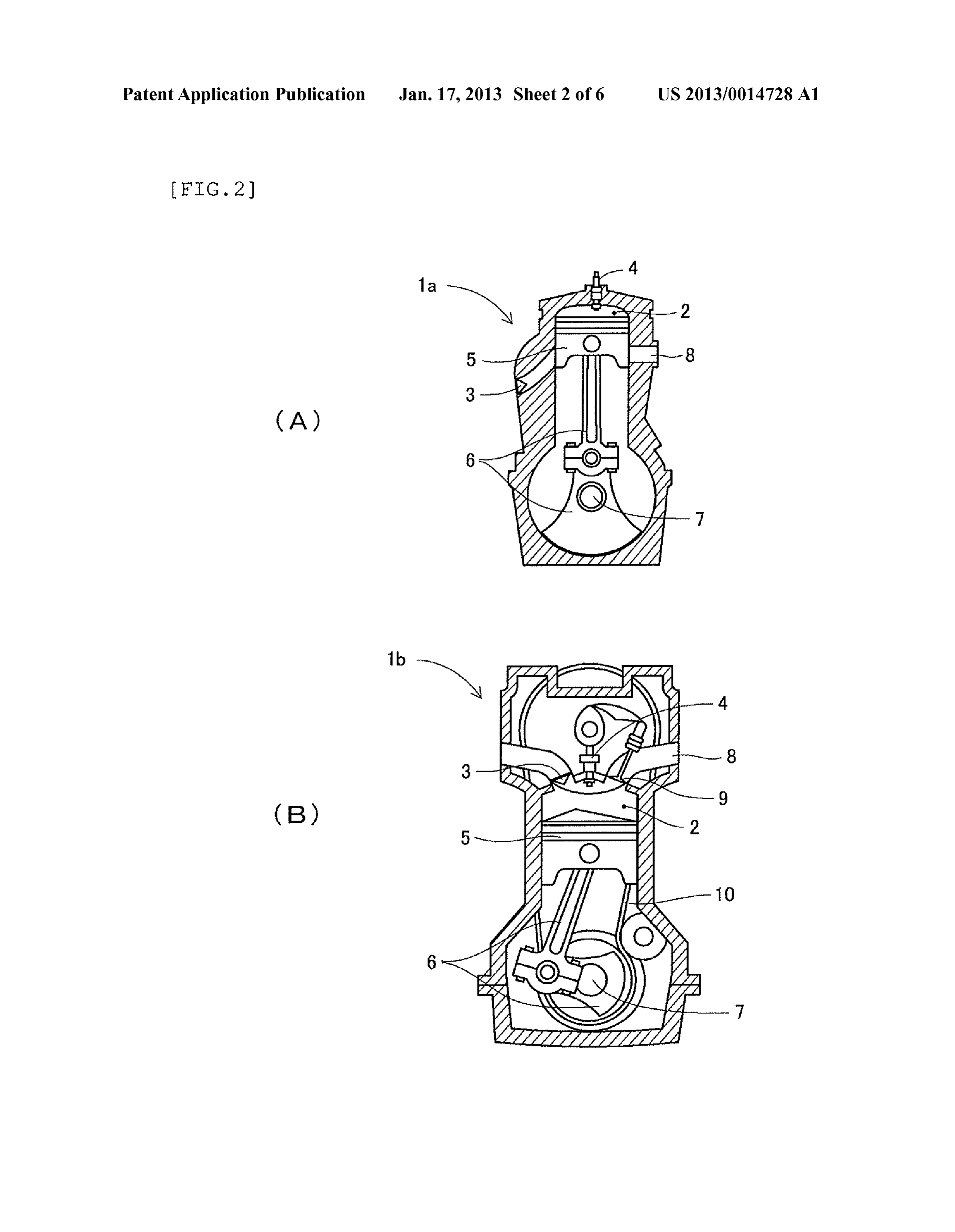
OXYHYDROGEN GAS
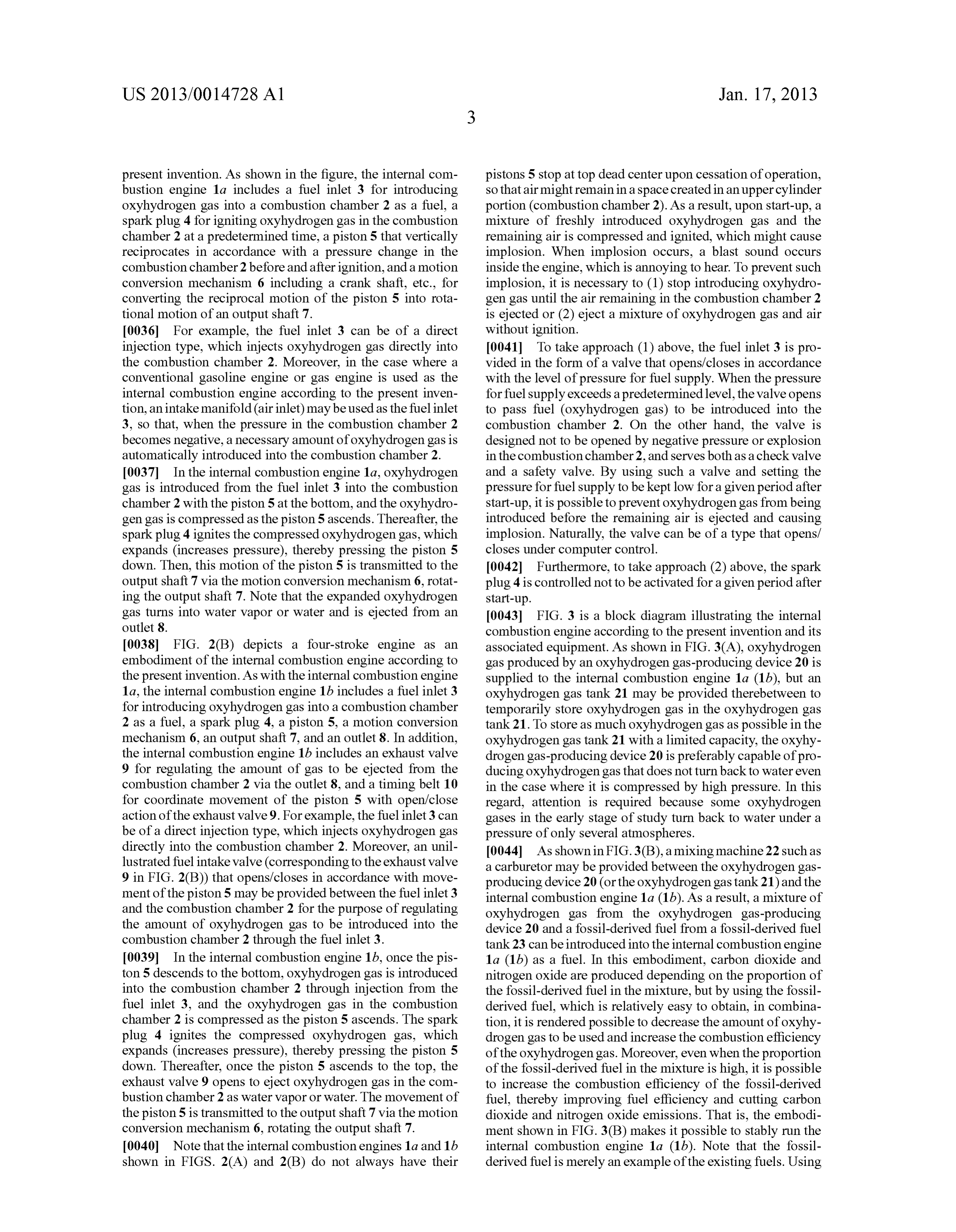
OXYHYDROGEN GAS 20
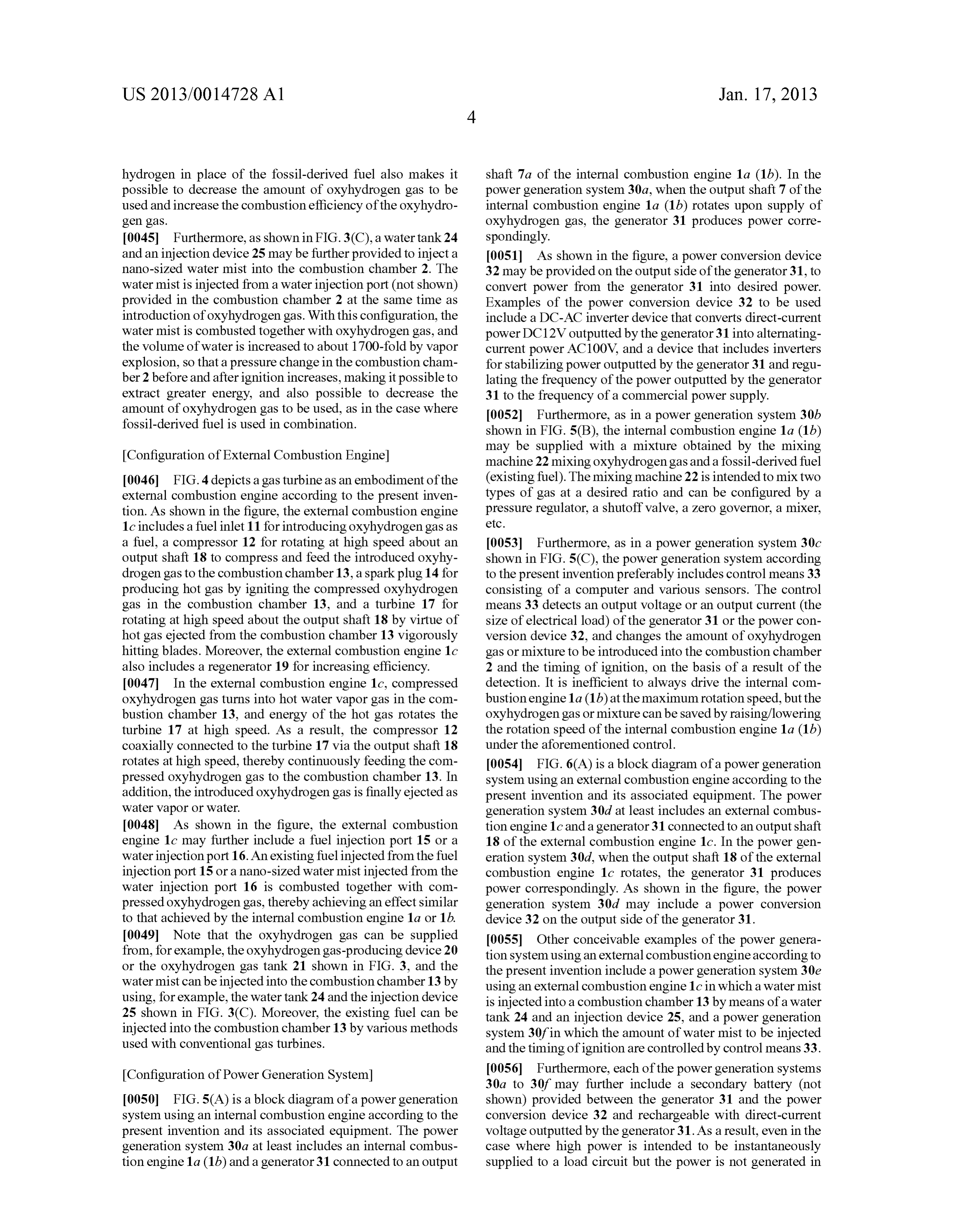
PRODUCING DEVICE
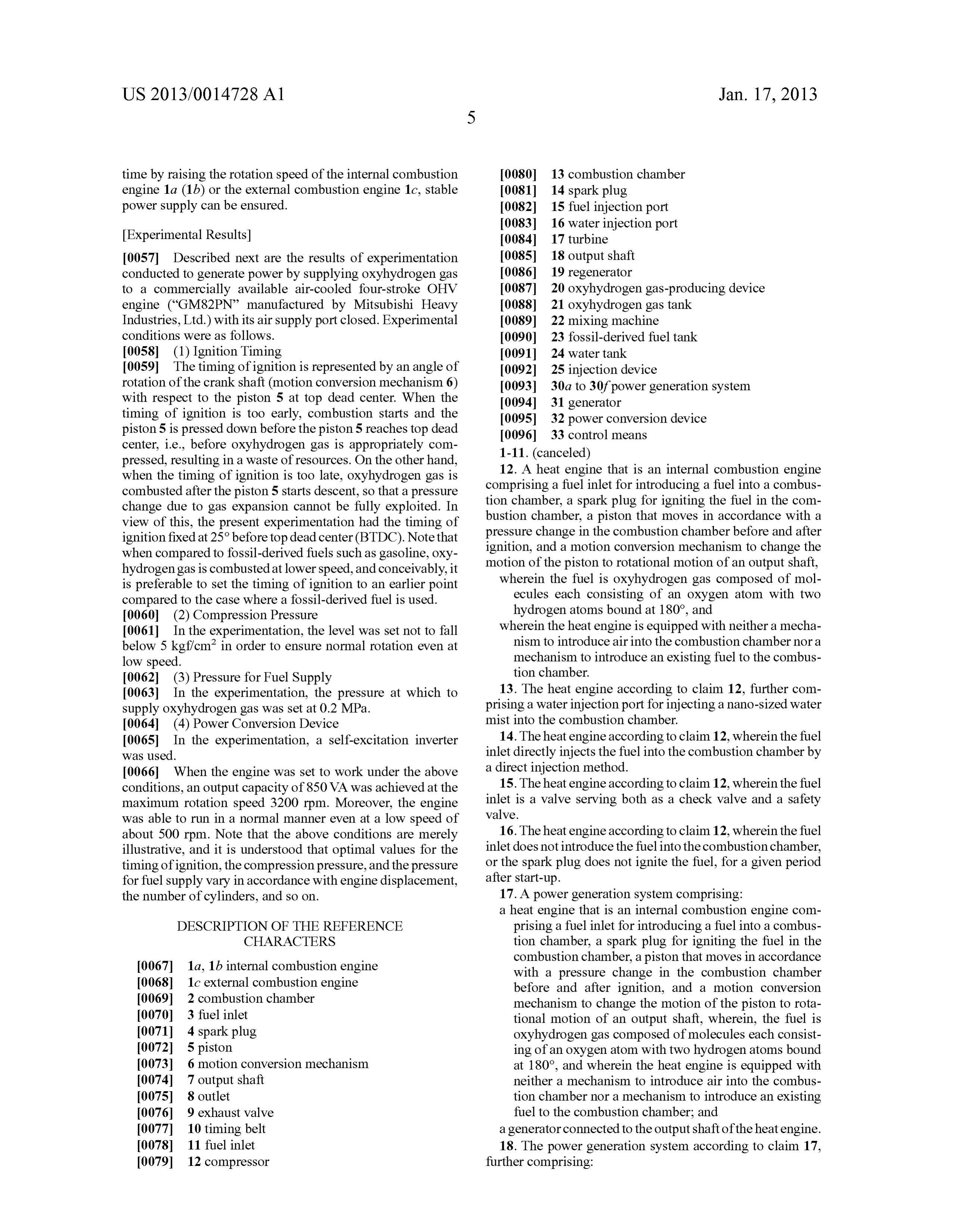
Page 5
Drawing sheet — no readable text.
Page 6
Drawing sheet — no readable text.
Page 7
Drawing sheet — no readable text.
Page 8
US 2013/OO 14728A1 Jan. 17, 2013
HEAT ENGINE AND POWER GENERATION dioxide and nitrogen oxide to be produced, to a certain SYSTEMUSING THE HEAT ENGINE degree. However, so long as the fossil-derived fuel is used as a fuel, it is not possible to eliminate production of carbon
TECHNICAL FIELD dioxide and nitrogen oxide.
0001. The present invention relates to a heat engine 0008 Furthermore, by using hydrogen as a fuel in place of including an internal or external combustion engine and a the fossil-derived fuel, it is rendered possible to eliminate power generation system using the heat engine. production of carbon dioxide and nitrogen oxide. However, heat engines of such a type, as with conventional heat engines,
BACKGROUND ART require complex mechanisms to strictly regulate the mixing ratio of hydrogen and air and introduce air into the combus 0002 Generally, in an internal combustion engine, such as tion chambers.
a two-stroke or four-stroke engine, a mixture of fossil-derived 0009. The present invention has been achieved under the fuel. Such as gasoline, heavy oil, light oil, or propanegas, and above circumstances, with a problem thereof being to provide air is combusted in a combustion chamber, causing a pressure a heat engine that emits neither carbon dioxide nor nitrogen change in the combustion chamber to generate energy. Spe oxide and is capable of dispensing with a mechanism to cifically, conventional internal combustion engines use both introduce air into a combustion chamber and a mechanism to the fossil-derived fuel and air to generate energy, and there regulate the mixing ratio of fuel and air, thereby achieving a fore cannot dispense with a mechanism to regulate the mixing simplified structure, and another problem being to provide a ratio of fossil-derived fuel and air to be included in a mixture power generation system using the heat engine. and the amount of mixture to be fed into the combustion chamber. Examples of such a mechanism include a carburetor Solution to the Problems and a fuel injector.
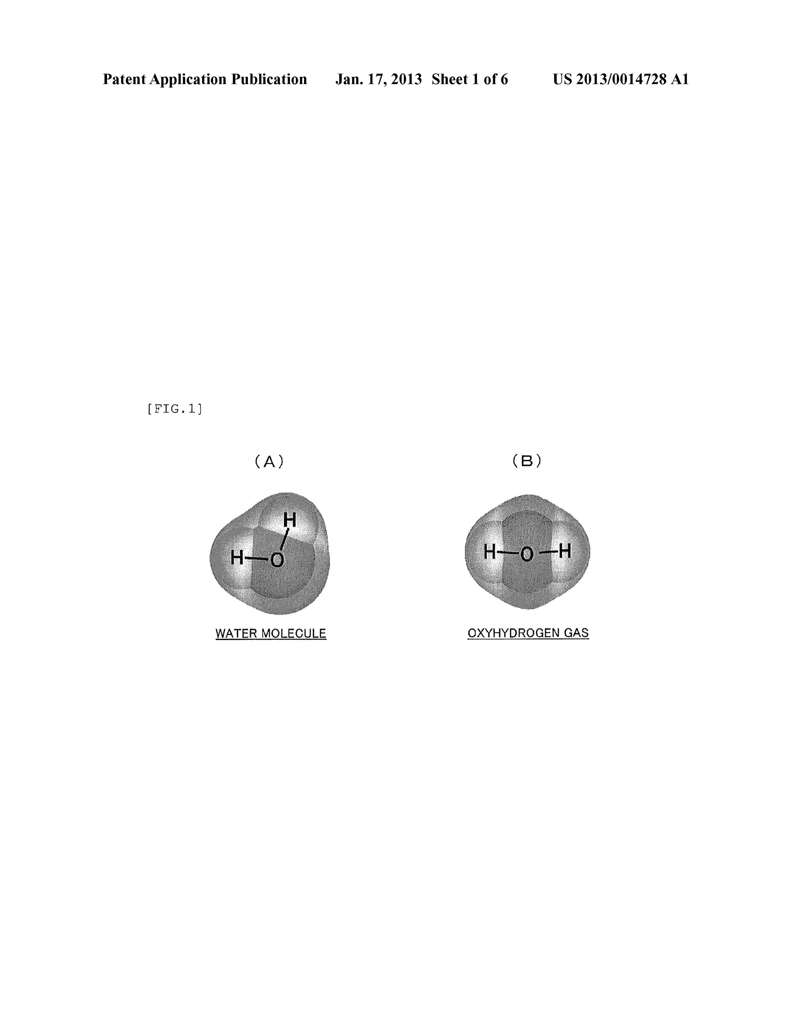
0003. Furthermore, in an external combustion engine such 0010. The present inventors diligently conducted studies as a gas turbine, a mixture of air compressed by a compressor to solve the aforementioned problems, and arrived at the and a fossil-derived fuel is combusted in a combustion cham present invention based on findings that the problems can be ber, energy of the resultant hot gas being Swiftly ejected from Solved by using as a fuel "oxyhydrogen gas containing the combustion chamber is used to rotate the turbine, and hydrogen and oxygen at a ratio of 2:1 (an example thereof is energy is extracted from the rotating shaft of the turbine. That hydrogen-oxygen gas disclosed in Japanese Patent No. is, as with conventional internal combustion engines, conven 3975467, in which an oxygen atom and two hydrogen atoms tional external combustion engines use both the fossil-de are considered to be bound at 180 degrees (see FIG. 1 (B)), rived fuel and air to generate energy. rather than at about 105 degrees as in a water molecule (see 0004. In the internal and external combustion engines FIG. 1(A))).
(collectively referred to below as “heat engines'), more than 0011 Specifically, aheat engine according to a first aspect a small amount of carbon dioxide (CO) is produced when a of the present invention is an internal combustion engine mixture is combusted. For example, where the fossil-derived including a fuel inlet for introducing oxyhydrogen gas into a fuel is gasoline or propanegas, 16 molecules or 3 molecules, combustion chamber as a fuel, a spark plug for igniting the respectively, of carbon dioxide, i.e., 16CO, or 3CO, are fuel in the combustion chamber, a piston that moves in accor produced, as shown in the following reaction formulae: dance with a pressure change in the combustion chamber before and after ignition, and a motion conversion mechanism to change the motion of the piston to rotational motion of an output shaft.
0012 Oxyhydrogen gas originally contains oxygen, and
Moreover, since 70% or more of air is nitrogen, nitrogen therefore does not need to be mixed with air upon combus oxide (NO) is produced together with such carbon dioxide tion. Moreover, since oxyhydrogen gas is composed of hydro when the mixture is combusted. gen and oxygen, water or water vapor is produced by com 0005 Carbon dioxide emissions from heat engines are one bustion. Thus, with this configuration, it is possible to of the factors of global warming, and have a seriously adverse eliminate carbon dioxide and nitrogen oxide emissions, and effect on global environment. In addition, nitrogen oxide omit a mechanism to regulate the mixing ratio of air and fuel exceeding a standard level causes photochemical Smog and and a mechanism to introduce air into the combustion cham acid rain, and also adversely affects the human respiratory ber, thereby achieving a simplified structure. In addition, system. Accordingly, particularly in recent years, research since this heat engine does not require air, energy can be and development has been actively conducted to reduce emis extracted from the output shaft even in a vacuum or in water. sions of these substances. 0013. In the heat engine according to the first aspect, the 0006 Note that the aforementioned conventional art is fuel can be a mixture of oxyhydrogen gas and an existing fuel. based on information about general technology obtained by 0014. The wording “existing fuel herein refers to a fuel as the present applicant, and as offiling of the present applica generally used in conventional heat engines. Examples of the tion, the applicant has no information about prior art docu “existing fuel include hydrogen and so on, in addition to ments that disclose the aforementioned conventional art and fossil-derived fuels, such as gasoline, heavy oil, light oil, other prior art. propane gas, natural gas, paraffin (kerosene), jet fuel, and
DISCLOSURE OF THE INVENTION
rocket fuel. In the case where a mixture obtained by mixing oxyhydrogen gas with a fossil-derived fuel is used, carbon dioxide and nitrogen oxide are produced depending on the
Problems to be Solved by the Invention proportion of the mixed fossil-derived fuel, but by using the 0007 Technologies obtained by research and develop fossil-derived fuel, which is relatively easy to obtain, in com ment as mentioned above can reduce the amount of carbon bination, it is rendered possible to decrease the amount of
Page 9
US 2013/OO 14728A1 Jan. 17, 2013
oxyhydrogen gas to be used, and increase the combustion 0024. Furthermore, a power generation system according efficiency of the oxyhydrogen gas. Moreover, even when the to a third aspect of the present invention includes a heat proportion of the mixed fossil-derived fuel is high, it is still engine according to the first or second aspect, and a generator possible to increase the combustion efficiency of the fossil connected to the output shaft of the heat engine. derived fuel, thereby improving fuel efficiency and cutting 0025. With this configuration using the heat engine carbon dioxide and nitrogen oxide emissions. Even when a according to the first or second aspect, it is possible to pro mixture with hydrogen is used as a fuel, it is possible to duce clean power while emitting neither carbon dioxide nor decrease the amount of oxyhydrogen gas to be used, and nitrogen oxide or cutting Such emissions. increase the combustion efficiency of the oxyhydrogen gas. 0026. Preferably, the power generation system according Thus, with this configuration, it is possible to stably run the to the third aspect further includes a power conversion device heat engine. It is conceived that this advantage is particularly for converting first power produced by the generator into beneficial in a transitional stage to diffusion before an infra desired second power, and control means for detecting either structure for stably Supplying oxyhydrogen gas is estab or both of an output Voltage and an output current of the lished. generator or the power conversion device, and changing the 0015 The heat engine according to the first aspect may amount of fuel to be introduced and the timing of ignition, on further include a water injection port for injecting a nano the basis of a result of the detection. sized water mist into the combustion chamber.
0016. With this configuration, the water mist is combusted EFFECT OF THE INVENTION together with oxyhydrogen gas, and the Volume of water is 0027. The present invention makes it possible to provide a increased to about 1700-fold by vapor explosion, so that a heat engine that emits neither carbon dioxide nor nitrogen pressure change in the combustion chamber before and after oxide and has a simplified structure compared to conventional ignition increases, making it possible to extract greater heat engines and also to provide a power generation system energy, and also possible to decrease the amount of oxyhy using the heat engine.
drogen gas to be used, as in the case where the fossil-derived fuel is used in combination. BRIEF DESCRIPTION OF THE DRAWINGS 0017 For example, the fuel inlet in the first aspect can be of a type that directly injects the fuel into the combustion 0028 FIG. 1 provides schematic diagrams (A) and (B) chamber by a direct injection method, or can be a valve respectively illustrating the structure of a water molecule and serving both as a check valve and a safety valve. the structure of oxyhydrogen gas. 0018. The heat engine according to the first aspect is desir (0029 FIG. 2 provides cross-sectional views (A) and (B) of ably configured such that the fuel inlet does not introduce the two-stroke and four-stroke engines, respectively, as examples fuel into the combustion chamber, or the spark plug does not of an internal combustion engine according to the present ignite the fuel, for a given period after start-up. invention.
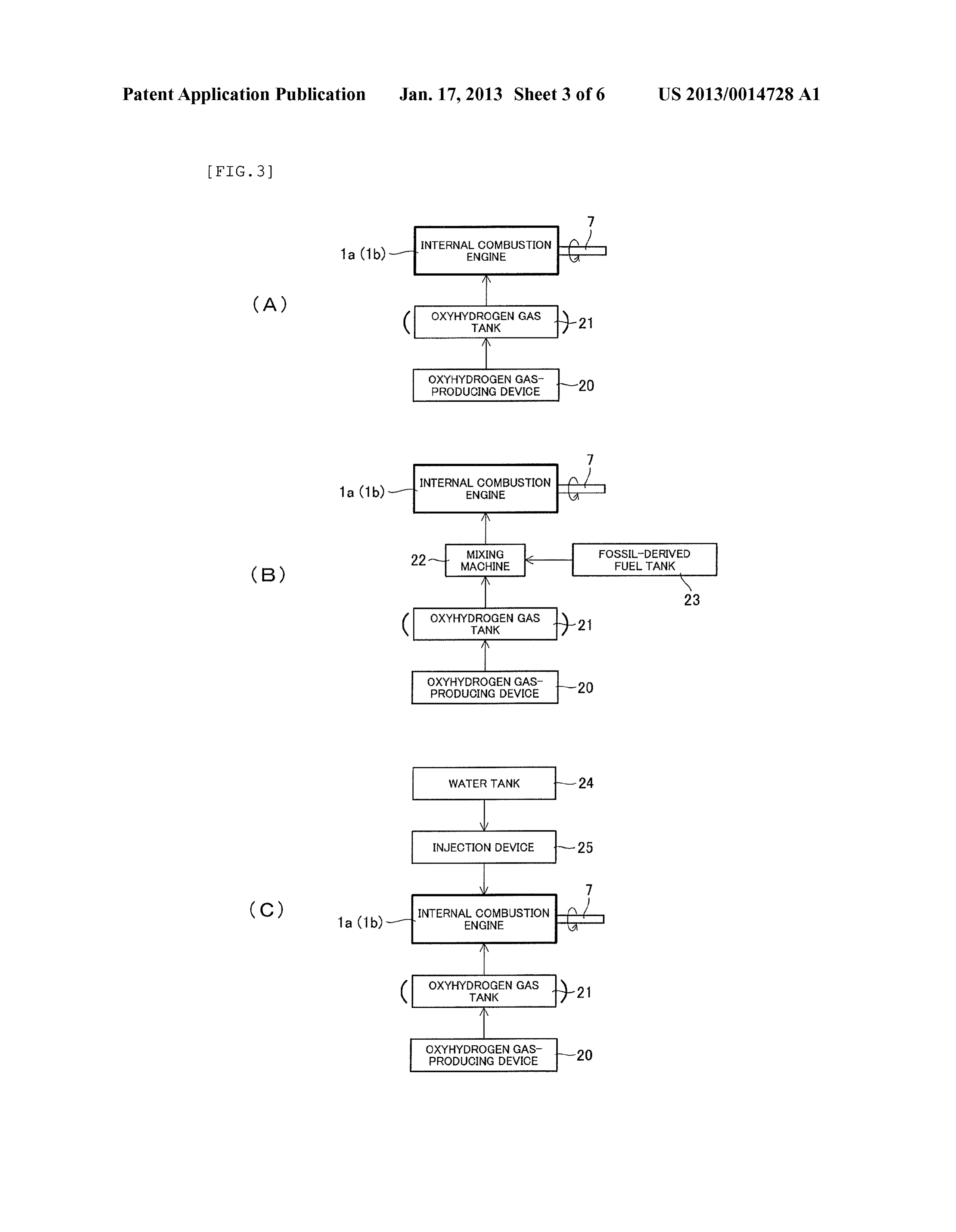
0019. With this configuration, it is possible to prevent 0030 FIG. 3 is a block diagram illustrating embodiments implosion from being caused immediately after start-up due of the internal combustion engine in FIG. 2 and its associated to combustion of a mixture of air accumulating in the com equipment.
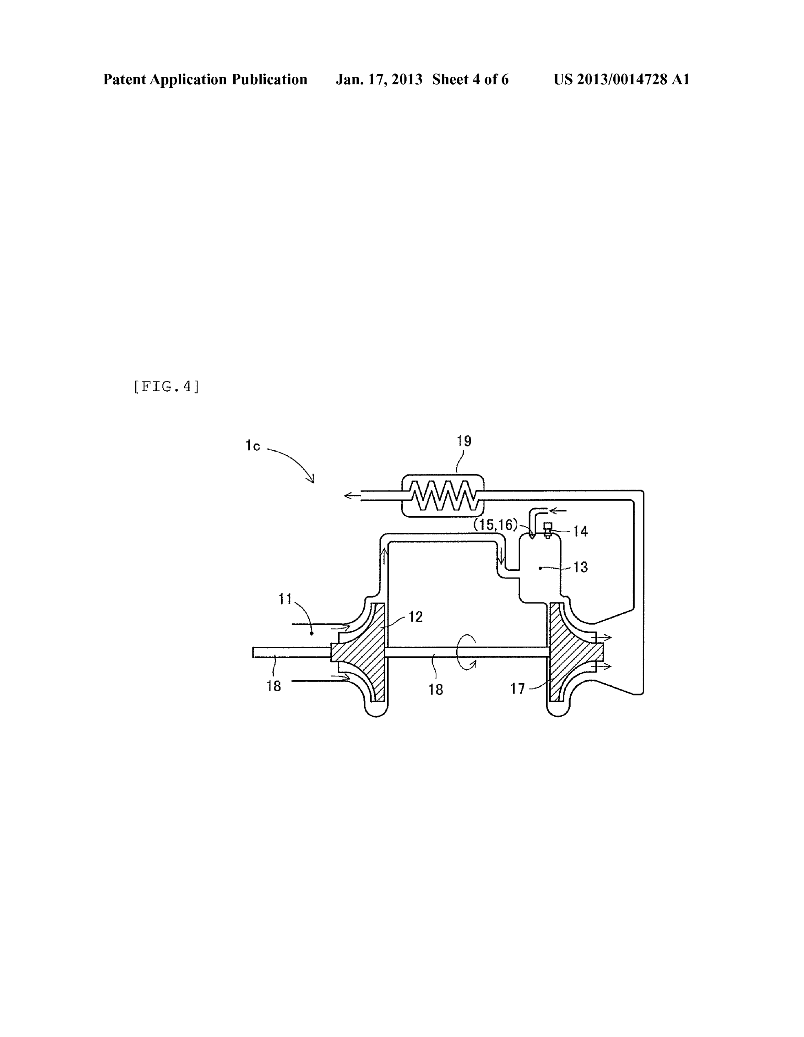
bustion chamber and freshly introduced oxyhydrogen gas. 0031 FIG. 4 is a schematic view of a gas turbine as an 0020. Furthermore, a heat engine according to a second example of an external combustion engine according to the aspect of the present invention is an external combustion present invention.
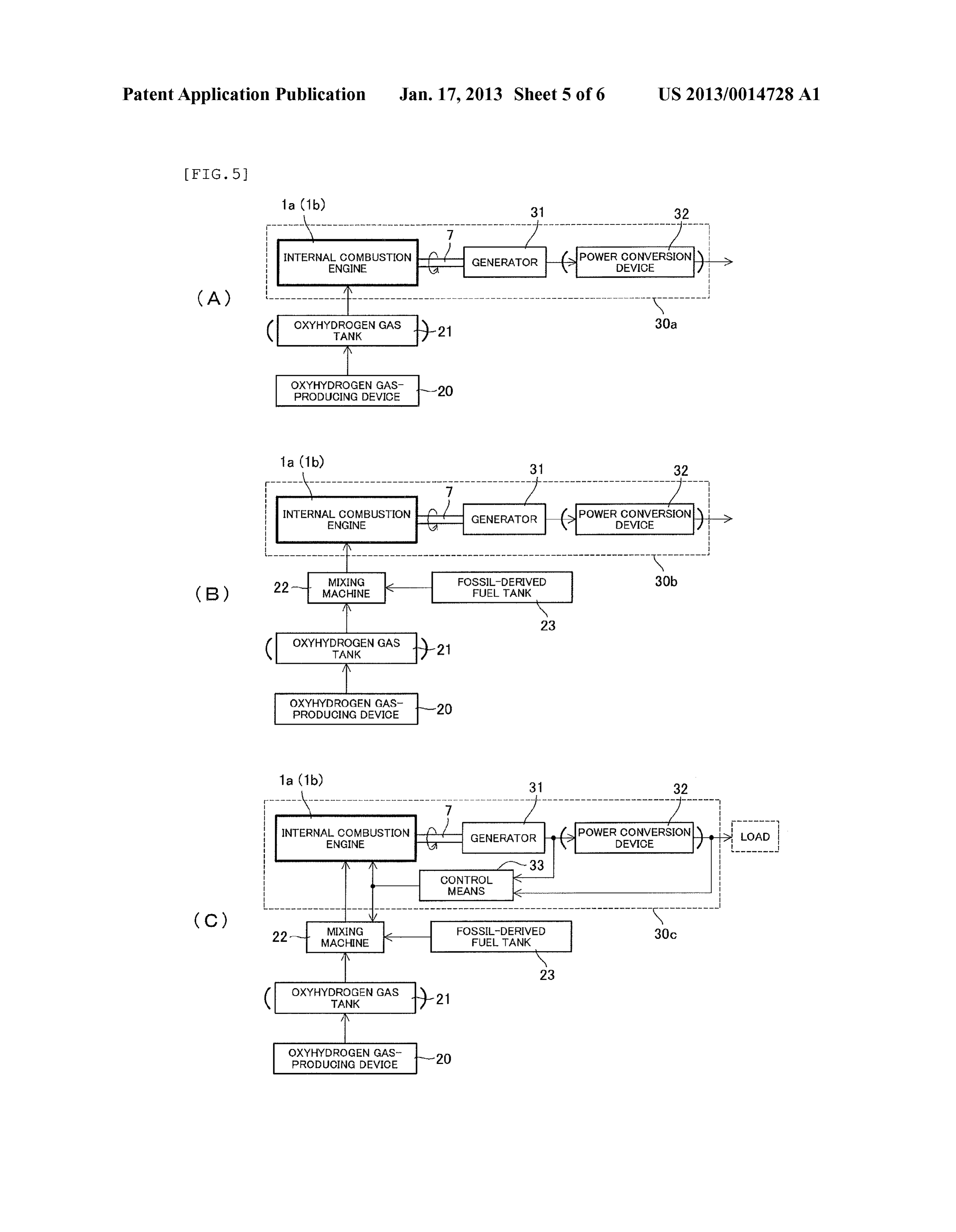
engine including a fuel inlet for introducing oxyhydrogen gas 0032 FIG. 5 is a block diagram illustrating embodiments as a fuel, a compressor for rotating about an output shaft to of a power generation system according to the present inven compress and feed the introduced fuel to a combustion cham tion, including an internal combustion engine, and its associ ber, a spark plug for producing hot gas by igniting the com ated equipment.
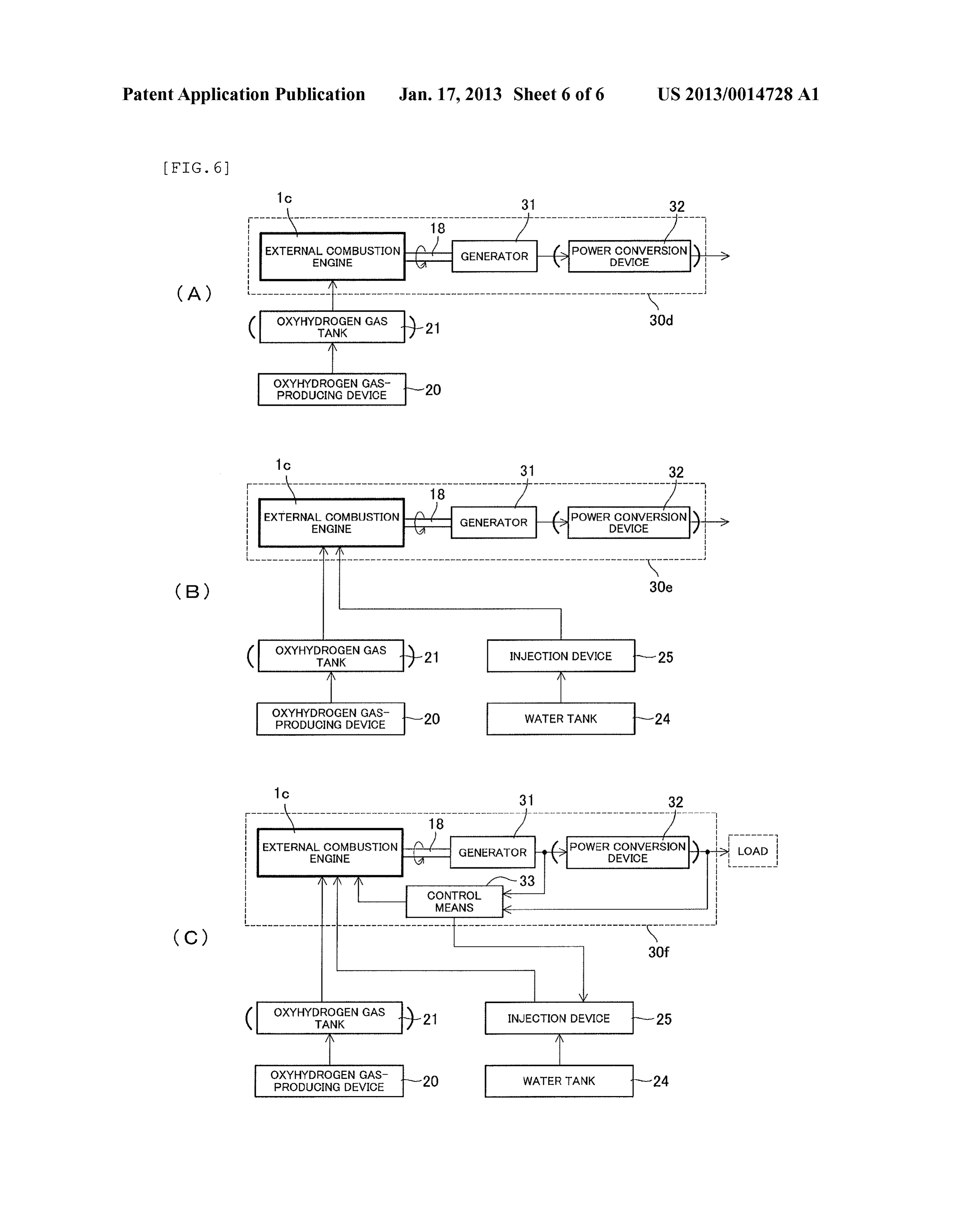
pressed fuel in the combustion chamber, and a turbine that is 0033 FIG. 6 is a block diagram illustrating embodiments caused to rotate about the output shaft by the hot gas ejected of a power generation system according to the present inven from the combustion chamber. tion, including an external combustion engine, and its asso ciated equipment.
0021. With this configuration, it is possible to eliminate carbon dioxide and nitrogen oxide emissions, as in the case of MODE FOR CARRYING OUT THE INVENTION the heat engine (internal combustion engine) according to the first aspect. Moreover, since this heat engine does not require 0034. Hereinafter, preferred embodiments of a heat engine air, energy can be extracted from the output shaft even in a and a power generation system according to the present vacuum or in water. invention will be described with reference to the accompany 0022. The heat engine according to the second aspect may ing drawings. Note that in the following descriptions, two further include a fuel injection port for injecting an existing stroke and four-stroke engines will be taken as examples of an fuel into the combustion chamber, and a water injection port internal combustion engine, but the internal combustion for injecting a nano-sized water mist into the combustion engine may be of another type such as a rotary engine using chamber. rotary pistons called rotors, in place of a crank mechanism. 0023. With this configuration, it is possible to increase the Moreover, in the following descriptions, a gas turbine will be combustion efficiency of the oxyhydrogen gas while decreas taken as an example of an external combustion engine, but the ing the amount of the oxyhydrogen gas to be used, and also external combustion engine is not limited to this. possible to extract greater energy by taking advantage of Configuration of Internal Combustion Engine vapor explosion of the water mist, as in the case of the heat engine (internal combustion engine) according to the first 0035 FIG.2(A) depicts a two-stroke engine as an embodi aspect. ment of the internal combustion engine according to the
Page 10
US 2013/OO 14728A1 Jan. 17, 2013
present invention. As shown in the figure, the internal com pistons 5 stop at top dead center upon cessation of operation, bustion engine 1a includes a fuel inlet 3 for introducing so that air might remain in a space created in an upper cylinder oxyhydrogen gas into a combustion chamber 2 as a fuel, a portion (combustion chamber 2). As a result, upon start-up, a spark plug 4 for igniting oxyhydrogen gas in the combustion mixture of freshly introduced oxyhydrogen gas and the chamber 2 at a predetermined time, a piston 5 that vertically remaining air is compressed and ignited, which might cause reciprocates in accordance with a pressure change in the implosion. When implosion occurs, a blast Sound occurs combustion chamber 2 before and after ignition, and a motion inside the engine, which is annoying to hear. To prevent such conversion mechanism 6 including a crank shaft, etc., for implosion, it is necessary to (1) stop introducing oxyhydro converting the reciprocal motion of the piston 5 into rota gen gas until the air remaining in the combustion chamber 2 tional motion of an output shaft 7. is ejected or (2) eject a mixture of oxyhydrogen gas and air 0036. For example, the fuel inlet 3 can be of a direct without ignition.
injection type, which injects oxyhydrogen gas directly into 0041. To take approach (1) above, the fuel inlet 3 is pro the combustion chamber 2. Moreover, in the case where a vided in the form of a valve that opens/closes in accordance conventional gasoline engine or gas engine is used as the with the level of pressure for fuel supply. When the pressure internal combustion engine according to the present inven for fuel supply exceeds a predetermined level, the valve opens tion, an intake manifold (air inlet) may be used as the fuel inlet to pass fuel (oxyhydrogen gas) to be introduced into the 3, so that, when the pressure in the combustion chamber 2 combustion chamber 2. On the other hand, the valve is becomes negative, a necessary amount of oxyhydrogen gas is designed not to be opened by negative pressure or explosion automatically introduced into the combustion chamber 2. in the combustion chamber 2, and serves both as a check valve 0037. In the internal combustion engine 1a, oxyhydrogen and a safety valve. By using Such a valve and setting the gas is introduced from the fuel inlet 3 into the combustion pressure for fuel supply to be kept low for a given period after chamber 2 with the piston 5 at the bottom, and the oxyhydro start-up, it is possible to prevent oxyhydrogen gas from being gen gas is compressed as the piston 5 ascends. Thereafter, the introduced before the remaining air is ejected and causing spark plug 4 ignites the compressed oxyhydrogen gas, which implosion. Naturally, the valve can be of a type that opens/ expands (increases pressure), thereby pressing the piston 5 closes under computer control.
down. Then, this motion of the piston 5 is transmitted to the 0042. Furthermore, to take approach (2) above, the spark output shaft 7 via the motion conversion mechanism 6, rotat plug 4 is controlled not to be activated for a given period after ing the output shaft 7. Note that the expanded oxyhydrogen start-up.
gas turns into water vapor or water and is ejected from an 0043 FIG. 3 is a block diagram illustrating the internal outlet 8. combustion engine according to the present invention and its 0038 FIG. 2(B) depicts a four-stroke engine as an associated equipment. As shown in FIG. 3(A), oxyhydrogen embodiment of the internal combustion engine according to gas produced by an oxyhydrogen gas-producing device 20 is the present invention. As with the internal combustion engine Supplied to the internal combustion engine 1a (1b), but an 1a, the internal combustion engine 1b includes a fuel inlet 3 oxyhydrogen gas tank 21 may be provided therebetween to for introducing oxyhydrogen gas into a combustion chamber temporarily store oxyhydrogen gas in the oxyhydrogen gas 2 as a fuel, a spark plug 4, a piston 5, a motion conversion tank 21. To store as much oxyhydrogen gas as possible in the mechanism 6, an output shaft 7, and an outlet 8. In addition, oxyhydrogen gas tank 21 with a limited capacity, the oxyhy the internal combustion engine 1b includes an exhaust valve drogen gas-producing device 20 is preferably capable of pro 9 for regulating the amount of gas to be ejected from the ducing oxyhydrogen gas that does not turn back to water even combustion chamber 2 via the outlet 8, and a timing belt 10 in the case where it is compressed by high pressure. In this for coordinate movement of the piston 5 with open/close regard, attention is required because some oxyhydrogen action of the exhaust valve 9. For example, the fuel inlet 3 can gases in the early stage of study turn back to water under a be of a direct injection type, which injects oxyhydrogen gas pressure of only several atmospheres. directly into the combustion chamber 2. Moreover, an unil 0044 As shown in FIG.3(B), a mixing machine 22 such as lustrated fuel intake valve (corresponding to the exhaust valve a carburetor may be provided between the oxyhydrogen gas 9 in FIG. 2(B)) that opens/closes in accordance with move producing device 20 (or the oxyhydrogen gas tank21) and the ment of the piston 5 may be provided between the fuel inlet 3 internal combustion engine 1a (1b). As a result, a mixture of and the combustion chamber 2 for the purpose of regulating oxyhydrogen gas from the oxyhydrogen gas-producing the amount of oxyhydrogen gas to be introduced into the device 20 and a fossil-derived fuel from a fossil-derived fuel combustion chamber 2 through the fuel inlet 3. tank 23 can be introduced into the internal combustion engine 0039. In the internal combustion engine 1b, once the pis 1a (1b) as a fuel. In this embodiment, carbon dioxide and ton 5 descends to the bottom, oxyhydrogen gas is introduced nitrogen oxide are produced depending on the proportion of into the combustion chamber 2 through injection from the the fossil-derived fuel in the mixture, but by using the fossil fuel inlet 3, and the oxyhydrogen gas in the combustion derived fuel, which is relatively easy to obtain, in combina chamber 2 is compressed as the piston 5 ascends. The spark tion, it is rendered possible to decrease the amount of oxyhy plug 4 ignites the compressed oxyhydrogen gas, which drogen gas to be used and increase the combustion efficiency expands (increases pressure), thereby pressing the piston 5 of the oxyhydrogen gas. Moreover, even when the proportion down. Thereafter, once the piston 5 ascends to the top, the of the fossil-derived fuel in the mixture is high, it is possible exhaust valve 9 opens to eject oxyhydrogen gas in the com to increase the combustion efficiency of the fossil-derived bustion chamber 2 as water vapor or water. The movement of fuel, thereby improving fuel efficiency and cutting carbon the piston 5 is transmitted to the output shaft 7 via the motion dioxide and nitrogen oxide emissions. That is, the embodi conversion mechanism 6, rotating the output shaft 7. ment shown in FIG. 3(B) makes it possible to stably run the 0040. Note that the internal combustion engines 1a and 1b internal combustion engine 1a (1b). Note that the fossil shown in FIGS. 2(A) and 2CB) do not always have their derived fuel is merely an example of the existing fuels. Using
Page 11
US 2013/OO 14728A1 Jan. 17, 2013
hydrogen in place of the fossil-derived fuel also makes it shaft 7a of the internal combustion engine 1a (1b). In the possible to decrease the amount of oxyhydrogen gas to be power generation system 30a, when the output shaft 7 of the used and increase the combustion efficiency of the oxyhydro internal combustion engine 1a (1b) rotates upon Supply of gen gas. oxyhydrogen gas, the generator 31 produces power corre 0045. Furthermore, as shown in FIG.3(C), a water tank 24 spondingly.
and an injection device 25 may be further provided to inject a 0051. As shown in the figure, a power conversion device nano-sized water mist into the combustion chamber 2. The 32 may be provided on the output side of the generator 31, to water mist is injected from a water injection port (not shown) convert power from the generator 31 into desired power. provided in the combustion chamber 2 at the same time as Examples of the power conversion device 32 to be used introduction of oxyhydrogen gas. With this configuration, the include a DC-AC inverter device that converts direct-current water mist is combusted together with oxyhydrogen gas, and power DC12V outputted by the generator 31 into alternating the volume of water is increased to about 1700-fold by vapor current power AC10OV, and a device that includes inverters explosion, so that a pressure change in the combustion cham for stabilizing power outputted by the generator 31 and regu ber 2 before and after ignition increases, making it possible to lating the frequency of the power outputted by the generator extract greater energy, and also possible to decrease the 31 to the frequency of a commercial power Supply. amount of oxyhydrogen gas to be used, as in the case where 0.052 Furthermore, as in a power generation system 30b fossil-derived fuel is used in combination.
shown in FIG. 5(B), the internal combustion engine 1a (1b)
Configuration of External Combustion Engine may be Supplied with a mixture obtained by the mixing machine 22 mixing oxyhydrogen gas and a fossil-derived fuel 0046 FIG.4 depicts a gas turbine as an embodiment of the (existing fuel). The mixing machine 22 is intended to mix two external combustion engine according to the present inven types of gas at a desired ratio and can be configured by a tion. As shown in the figure, the external combustion engine pressure regulator, a shutoff valve, a Zero governor, a mixer, 1c includes a fuel inlet 11 for introducing oxyhydrogen gas as etc.
a fuel, a compressor 12 for rotating at high speed about an 0053. Furthermore, as in a power generation system 30c output shaft 18 to compress and feed the introduced oxyhy shown in FIG. 5(C), the power generation system according drogen gas to the combustion chamber 13, a spark plug 14 for to the present invention preferably includes control means 33 producing hot gas by igniting the compressed oxyhydrogen consisting of a computer and various sensors. The control gas in the combustion chamber 13, and a turbine 17 for means 33 detects an output Voltage or an output current (the rotating at high speed about the output shaft 18 by virtue of size of electrical load) of the generator 31 or the power con hot gas ejected from the combustion chamber 13 vigorously version device 32, and changes the amount of oxyhydrogen hitting blades. Moreover, the external combustion engine 1c gas or mixture to be introduced into the combustion chamber also includes a regenerator 19 for increasing efficiency. 2 and the timing of ignition, on the basis of a result of the 0047. In the external combustion engine 1c, compressed detection. It is inefficient to always drive the internal com oxyhydrogen gas turns into hot water vapor gas in the com bustion engine 1a (1b) at the maximum rotation speed, but the bustion chamber 13, and energy of the hot gas rotates the oxyhydrogen gas or mixture can be saved by raising/lowering turbine 17 at high speed. As a result, the compressor 12 the rotation speed of the internal combustion engine 1a (1b) coaxially connected to the turbine 17 via the output shaft 18 under the aforementioned control. rotates at high speed, thereby continuously feeding the com 0054 FIG. 6(A) is a block diagram of a power generation pressed oxyhydrogen gas to the combustion chamber 13. In system using an external combustion engine according to the addition, the introduced oxyhydrogen gas is finally ejected as present invention and its associated equipment. The power water vapor or water. generation system 30d at least includes an external combus 0048. As shown in the figure, the external combustion tion engine 1c and a generator 31 connected to an output shaft engine 1c may further include a fuel injection port 15 or a 18 of the external combustion engine 1c. In the power gen water injection port 16. An existing fuel injected from the fuel eration system 30d, when the output shaft 18 of the external injection port 15 or a nano-sized water mist injected from the combustion engine 1c rotates, the generator 31 produces water injection port 16 is combusted together with com power correspondingly. As shown in the figure, the power pressed oxyhydrogen gas, thereby achieving an effect similar generation system 30d may include a power conversion to that achieved by the internal combustion engine 1a or 1b. device 32 on the output side of the generator 31. 0049. Note that the oxyhydrogen gas can be supplied 0055. Other conceivable examples of the power genera from, for example, the oxyhydrogen gas-producing device 20 tion system using an external combustion engine according to or the oxyhydrogen gas tank 21 shown in FIG. 3, and the the present invention include a power generation system 30e water mist can be injected into the combustion chamber 13 by using an external combustion engine 1c in which a water mist using, for example, the water tank 24 and the injection device is injected into a combustion chamber 13 by means of a water 25 shown in FIG. 3(C). Moreover, the existing fuel can be tank 24 and an injection device 25, and a power generation injected into the combustion chamber 13 by various methods system 30f in which the amount of water mist to be injected used with conventional gas turbines. and the timing of ignition are controlled by control means 33. Configuration of Power Generation System 0056 Furthermore, each of the power generation systems 30a to 30f may further include a secondary battery (not 0050 FIG. 5(A) is a block diagram of a power generation shown) provided between the generator 31 and the power system using an internal combustion engine according to the conversion device 32 and rechargeable with direct-current present invention and its associated equipment. The power voltage outputted by the generator 31. As a result, even in the generation system 30a at least includes an internal combus case where high power is intended to be instantaneously tion engine 1a (1b) and a generator 31 connected to an output Supplied to a load circuit but the power is not generated in
Page 12
US 2013/OO 14728A1 Jan. 17, 2013
time by raising the rotation speed of the internal combustion 0080 13 combustion chamber engine 1a (1b) or the external combustion engine 1c, stable 0081. 14 spark plug power Supply can be ensured. I0082 15 fuel injection port
I0083) 16 water injection port
Experimental Results 0084 17 turbine 0057. Described next are the results of experimentation I0085 18 output shaft conducted to generate power by Supplying oxyhydrogen gas I0086) 19 regenerator to a commercially available air-cooled four-stroke OHV 0.087 20 oxyhydrogen gas-producing device engine (“GM82PN' manufactured by Mitsubishi Heavy 0088 21 oxyhydrogen gas tank
Industries, Ltd.) with its air Supply port closed. Experimental 0089 22 mixing machine conditions were as follows. 0090. 23 fossil-derived fuel tank 0058 (1) Ignition Timing 0091 24 water tank 0059. The timing of ignition is represented by an angle of 0092) 25 injection device rotation of the crank shaft (motion conversion mechanism 6) (0.093 30a to 30fpower generation system with respect to the piston 5 at top dead center. When the 0094 31 generator timing of ignition is too early, combustion starts and the (0.095 32 power conversion device piston 5 is pressed down before the piston 5 reaches top dead 0096. 33 control means center, i.e., before oxyhydrogen gas is appropriately com pressed, resulting in a waste of resources. On the other hand, 1-11. (canceled) when the timing of ignition is too late, oxyhydrogen gas is 12. A heat engine that is an internal combustion engine combusted after the piston 5 starts descent, so that a pressure comprising a fuel inlet for introducing a fuel into a combus change due to gas expansion cannot be fully exploited. In tion chamber, a spark plug for igniting the fuel in the com view of this, the present experimentation had the timing of bustion chamber, a piston that moves in accordance with a ignition fixed at 25° before top dead center (BTDC). Note that pressure change in the combustion chamber before and after when compared to fossil-derived fuels such as gasoline, oxy ignition, and a motion conversion mechanism to change the hydrogen gas is combusted at lower speed, and conceivably, it motion of the piston to rotational motion of an output shaft, is preferable to set the timing of ignition to an earlier point wherein the fuel is oxyhydrogen gas composed of mol compared to the case where a fossil-derived fuel is used. ecules each consisting of an oxygen atom with two 0060 (2) Compression Pressure hydrogen atoms bound at 180°, and 0061. In the experimentation, the level was set not to fall wherein the heat engine is equipped with neither a mecha below 5 kgf/cm in order to ensure normal rotation even at nism to introduce air into the combustion chamber nor a low speed. mechanism to introduce an existing fuel to the combus 0062 (3) Pressure for Fuel Supply tion chamber.
0063. In the experimentation, the pressure at which to 13. The heat engine according to claim 12, further com Supply oxyhydrogen gas was set at 0.2 MPa. prising a water injection port for injecting a nano-sized water 0064 (4) Power Conversion Device mist into the combustion chamber.
0065. In the experimentation, a self-excitation inverter 14. The heat engine according to claim 12, wherein the fuel was used. inlet directly injects the fuel into the combustion chamber by 0066. When the engine was set to work under the above a direct injection method.
conditions, an output capacity of 850VA was achieved at the 15. The heat engine according to claim 12, wherein the fuel maximum rotation speed 3200 rpm. Moreover, the engine inlet is a valve serving both as a check valve and a safety was able to run in a normal manner even at a low speed of valve.
about 500 rpm. Note that the above conditions are merely 16. The heat engine according to claim 12, wherein the fuel illustrative, and it is understood that optimal values for the inlet does not introduce the fuel into the combustion chamber, timing of ignition, the compression pressure, and the pressure or the spark plug does not ignite the fuel, for a given period for fuel Supply vary in accordance with engine displacement, after start-up.
the number of cylinders, and so on. 17. A power generation system comprising: a heat engine that is an internal combustion engine com
DESCRIPTION OF THE REFERENCE prising a fuel inlet for introducing a fuel into a combus CHARACTERS tion chamber, a spark plug for igniting the fuel in the 0067 1a, 1b internal combustion engine combustion chamber, a piston that moves in accordance with a pressure change in the combustion chamber 0068 1c external combustion engine before and after ignition, and a motion conversion 0069. 2 combustion chamber mechanism to change the motion of the piston to rota 0070 3 fuel inlet tional motion of an output shaft, wherein, the fuel is 0071 4 spark plug Oxyhydrogen gas composed of molecules each consist 0072 5 piston ing of an oxygen atom with two hydrogen atoms bound 0073 6 motion conversion mechanism at 180°, and wherein the heat engine is equipped with (0074 7 output shaft neither a mechanism to introduce air into the combus 0075 8 outlet tion chamber nor a mechanism to introduce an existing 0076 9 exhaust valve fuel to the combustion chamber; and 0.077 10 timing belt a generator connected to the output shaft of the heat engine. 0078 11 fuel inlet 18. The power generation system according to claim 17. (0079 12 compressor further comprising:
Page 13
US 2013/OO 14728A1 Jan. 17, 2013
a power conversion device for converting first power pro fuel to be introduced and the timing of ignition, on the duced by the generator into desired second power; and basis of a result of the detection. control means for detecting either or both of an output
Voltage and an output current of the generator or the power conversion device, and changing the amount of

Provenance
- Collection
- Patents citing this work
- Original assignee
- Masa International Corp
- Pages
- 13
- Method
- pdftotext (the PDF's own text layer) + pdftoppm 300dpi page scans
- Patent office record
- patents.google.com →
- Source
- Google Patents citing-documents table
- Inventors
- Yoriyasu Ozaki; Masakatsu Uchiyama; Masa International Corp
- Published
- 2013-01-17
- Transcribed from
- patentimages.storage.googleapis.com →