patent · US1715775
Apparatus for producing oil gas
4 June 1929
Page 1 — bibliographic record
June 4, 1929. F. T. NEWITT ET AL 1,715,775 APPARATUS FOR PRODUCING OIL. Gas
Filed March ll, 1924
NYNS
7% 2.N o 2 2 al 37 sNNa2N a2 S
147 A. INVENTORS
N Š N - S. A 7. Zar AP/2727 SNS

Page 2
Patented June 4, 1929. 1,715,775
UNITED STATES PATENT OFFICE.
FRANK. T. NEWITT, OF PLATTEVILLE, AND SIMEON H. LA PLANT AND LEWIS
I. TURNER, OFSALIDA, COLORADo, ASSIGNORSTO THEL. T. N. MANUFACTURING &
DEVELOPMENT
. AGREEMENT SYSTEM, UNDER
ORGANIZED of PLATTEVILLE, COLORADo,
THE LAws OF COLORADO.A COMMON-LAw TRUST
Application filed March 11, 1924. Serial No. 698,418.
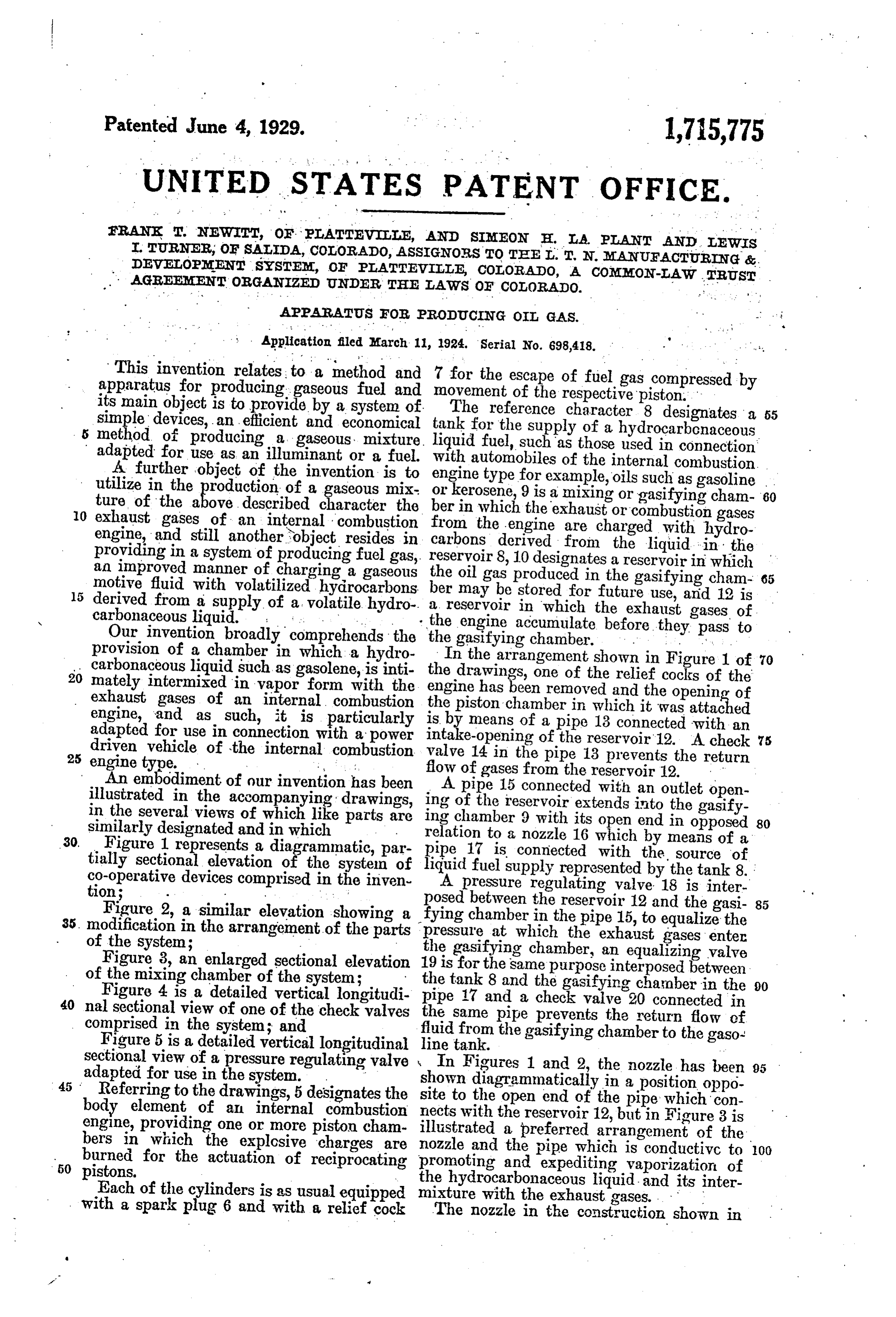
This invention relates to a method and apparatus for producing gaseous fuel and 7 for the escape of fuel gas compressed by its main object is to provide by a system of movement of the respective piston. simple devices, an efficient and economical tank for the supplycharacter
The reference
8 designates a 55 hydrocarbonaceous 5 method of producing a gaseous mixture. liquid fuel, such as those used in connection adapted for use as an illuminant or a fuel. with automobiles of the internal combustion. A further object of the invention is to : utilize in the production of a gaseous mix engine type for example, oils such as gasoline . . ture of the above, described character the ber in which9the or kerosene, is a mixing orgasifying cham-60 10 exhaust gases of an internal combustion from the engineexhaust are or combustion gases charged with hydro engine, and still another object resides in carbons derived from the liquid in the providing in a system of producing fuel gas, reservoir 8, 10 designates a reservoir an improved manner of charging a gaseous the oil gas produced in the gasifying cham- in which motive fluid with volatilized hydrocarbons ber may be stored for future use, and 12 is 65 15 carbonaceous derived from liquid.
a supply. of. a. . volatile
. . a reservoir in which the exhaust gases of
Our invention broadly comprehends the the the gasifying engine accumulate chamber. before
provision of a chamber in which a hydro . . carbonaceous liquid such as gasolene, is inti theIndrawings, the arrangement shown in Figure 1 of 70 20 mately intermixed in vapor form with the engine has beenoneremoved of the relief cocks of the and the opening of exhaust gases of an internal combustion the piston chamber in which it was attached engine, and as such, it is particularly is by means of a pipe 13 connected with an adapted for use in connection with a power intake-opening of the reservoir'12. A check 75 driven vehicle of the internal combustion valve 14 in the pipe 13 prevents the return
An embodiment of our invention has been flow of gases from the reservoir 12. illustrated in the accompanying drawings, ing of the15reservoir
A pipe connected with an outlet open extends into the gasify in the several views of which like parts are ing chamber 9 with its open end in opposed 80 similarly designated and in which 30. Figure 1 represents a diagrammatic, par relation to a nozzle 16 which by means of a tially sectional elevation of the system of pipe liquid 17 is connected with the source of fuel supply represented by the tank 8.
co-operative devices comprised in the inven A pressure regulating valve 18 is inter
posed between
Figure 2, a similar elevation showing a fying chamber in the reservoir 12 and the gasi- 85 35, modification in the arrangement of the parts pressure at whichthethepipe 15, to equalize the exhaust gases enter of the system; the gasifying chamber, an equalizing valve Figure 3, an enlarged sectional elevation 19 is for the same purpose interposed between of the mixing chamber of the system;
Figure 4 is a detailed vertical longitudi thepipe tank 8 and the gasifying chamber in the 90 17 and a check valve 20 connected in 40 nal sectional view of one of the check valves the same pipe prevents the return flow of comprised in the system; and
Figure 5 is a detailed vertical longitudinal line tank. the gasifying chamber to the gaso fluid from sectional view of a pressure regulating valve In Figures 1 and 2, the nozzle has been 95 adapted for use in the system. . shown diagrammatically in a position oppo 45 Referring to the drawings, 5 designates the site to the open end of the pipe which con body element of an internal combustion nects engine, providing one or more piston cham illustrated with the reservoir 12, but in Figure 3 is bers in which the explosive charges are nozzle and athepreferred arrangement of the burned for the actuation of reciprocatings promoting and expediting isvaporization 50 pistons.
pipe which conductive to 100
Each of the cylinders is as usual equippe the hydrocarbonaceous liquid. and its inter with a spark plug 6 and with a relief cock mixture with the exhaust gases. . . . . The nozzle in the construction shown in
Page 3
Figure 3, is constituted by the end of the so-called vacuum system, this pressure is au pipe 15 leading from the tank 12, which as in tomatically produced in the operation of the the diagrammatic view, is disposed in aline engine, but it may be obtained by the use of ment with the end of the pipe 17 connected a pump or other similar compliance as indi to the reservoir 8. ', cated at 30 in Figure 2, or it may be sup The nozzle extends, however, into the plied by connecting the upper portion of pipe 15 and its orifice is controlled by a the tank, with the combustion space of an tapering needle valve 21 at the end of a stem other piston chamber of the engine through 22 which is slidably supported in a bearing the medium of a pipe .31 as shown in 23. - Figure 1. . . .
The end portion of the pipe 15 extending The last mentioned method of supplying into the mixing chamber, is preferably con the pressure to the gasoline has the added nected with the body portion of the same advantage of adding to the carbonaceous through the medium of an elbow 24 provided fuel by any unconsumed or uncombusted with a stuffing box 25 through which the fuel which may. be left in the combustion 80 stem 22 passes for its connection with a hand chamber through imperfect combustion. lever, pedal or other device to effect, its In the operation of the system, the gaso longitudinal movement for the adjustment line forcibly introduced into the gasifying of the valve 21 relative to the orifice of the chamber is brought into violent contact nozzle. S. with the hot exhaust gases which enter the 85 The valve has exteriorly of the nozzle a chamber likewise under pressure. Theim disk-shaped collar 26 upon which the liquid pact of the two fluids causes the liquid to fuel discharged from the pipe 17 impinges be finely divided and diffused in the hot and which causes it to be finely divided and gases discharged from the engine with the 25 diffused into the hot exhaust or combustion result that it is completely vaporized and gases entering the gasifying chamber in that condition is intimately and thor through the pipe 15. The discharge end of oughly intermixed with the exhaust gases. a conduit 15 forms a tubular outlet which The result of the mixture thus produced is extends through one wall of the mixing a gaseous fuel which is useful as either a 30 chamber and terminates short of the oppo fuel or an illuminant. . . . . . . . . . 9. site wall through which the nozzle extends. By the use of a valve controlling the dis The nozzle which is of a diameter less than charge of liquid from the nozzle, as shown that of the tubular outlet projects into the at 32 in Figures 1 and 2, or as illustrated in same, and the deflecting or baffle disk 26 detail in Figure 3, the richness of the mix which is arranged in the path of the dis ture may be regulated according to warying OO charge from the nozzle is of a diameter less conditions and requirements, and it will be than that of the interior of the tubular out readily apparent that although the reser let and it partially constricts the same and it voirs 12 and 10 are advantageous and under forms an annular space or passage between certain circumstances indispensable, the op 40 its periphery and the walls of the tubular crative condition of the system is not detri 05 outlet. The exhaust gases pass over or mentally impaired by placing the mixing across the periphery of the baffle disk or chamber in direct connection with the ex member in an annular stream against which haust opening of the engine or by conduct the gasoline from the nozzle is sprayed. As ing the mixture produced in the chamber 9 45. the outlet and the baffle are heated by the directly to the burners. O exhaust gases the gasoline is in the form of It will furthermore be understood that if a fine spray or vapor when it commingles so desired, the exhaust gases may be ob with the exhaust gases and as it leaves the tained by a suitable valve controlled con outlet pipe into the mixing chamber it is nection with the exhaust-manifold of the 50 in gaseous form and thoroughly mixes with engine and that any appliance of the gen 5 the exhaust gases in the mixing chamber. eral type illustrated in Figures 4 and 5 may The gasifying chamber has an outlet be employed to regulate and check the flow opening which by means of a pipe 37 is con of fluids between the elements of the system nected with the reservoir 10, a check valve as hereinbefore described. . . . . . . . . . . . . . 55 40 in the pipe prevents the return flow of The system illustrated in Figure 2 differs 20 the oil gas to the mixing chamber, and a from the other only in that it provides for valve-controlled pipe 29 connected with an a repeated charge of the exhaust gases with outlet of the reservoir 10 is provided to con hydrocarbons derived from the liquid in the duct the oil gas to the burners of a stove, tank 8 before the mixture passes to the 60 lamp or other similar contrivance. reservoir 10. The outlet of the primary 25 It is preferred that in the operation of gasifying chamber is in this construction, the system, the gasoline or other volatile provided with a pipe 33 which extends into liquid be forced from the tank and into the a secondary gasifying chamber 34 in axial. gasifying chamber under mechanical pres alinement with a nozzle 35 at the end of an 65 sure. In motor vehicles equipped with the extension 36 of the gasoline feed pipe 17 30
Page 4
and an outlet of the secondary mixing said combustion tubular gas conduit outlet extending intohaving an open the gasifying chamber is conriected to the storage tank chamber by means of a pipe 37, manually adjusted minatingthrough one wall thereof and ter. valves 38 and 39 in the pipes control the connectedshort of an opposite wall, a nozzle the end of the oil conduit and 70 flow of gases and liquid to the secondary extending tothrough the said opposite wall of chamber and a check valve 40 prevents the the gasifying chamber, a valve extending return flow of gases from the reservoir 10 into said nozzle for controlling the discharge as before.
While our process and apparatus as above therefrom a baffle and having a stem provided with member of less diameter than the
O described, are particularly adapted for the production of gas suitable for use as a fuel same and formingpartially tubular outlet and a constricting passage between the its in heater or stoves and other similar ap periphery and the said tubular outlet, said pliances, or as an illuminant in lamps, it baffle member being arranged in the path of will be evident that under favorable con 80 ditions it may also be employed as an ex the4.discharge of the nozzle. An apparatus for producing oil gas plosion mixture for use in the operation of including in combination; an oil gasifying an internal combustion engine. chamber, an oil tank, an oil conduit leading Having thus described our invention, from the storage what we claim and desire to secure by Let ber, a combustiontankgas to the gasifying cham 85.
conduit leading from a 20 ters Patent is: combustion chamber of an internal combus 1. An apparatus for producing oil gas tion engine to the oil gasifying chamber, including in combination; an oil gasifying said combustionextending gas conduit chamber, an oil tank, an oil conduit leading tubular from the storage tank to the gasifying cham chamberoutlet intohaving an open the gasifying ber, a combustion gas conduit leading from minating through one wall thereof and ter. 90 a combustion chamber of an internal com short of an opposite wall, a nozzle connected to the end of the oil conduit and bustion engine to the oil gasifying chamber, said combustion gas conduit having an open extending through the said opposite wall of tubular outlet extending into the gasifying the ing gasifying chamber, and a valve extend 95 into said nozzle for controlling the dis 30 chamber through one wall thereof and ter charge thereof and having a stem arranged minating short of an opposite wall, a nozzle within and extending along the tubular out connected to the end of the oil conduit and let to the exterior thereof, said stem being extending through the said opposite wall of provided with a baffle disk of less diameter the gasifving chamber and discharging into than the tubular outlet and partially con 00 the combustion gas tubular outlet, and an stricting the same and forming an annular oil gas outlet leading from the gasifying passage around it. chamber. 5. An apparatus for producing oil gas in 2. An apparatus for producing oil gas including in combination; an oil gasifying cluding in combination an oil gasifying 05 . chamber, a conduit for combustion gases 40 chamber, an oil tank, an oil conduit leading extending through one wall of the gasifying from the storage tank to the gasifying cham chamber and terminating short of the oppo ber, a combustion gas conduit leading from site wall, a nozzle extending through the a combustion chamber of an internal com latter wall and being of less diameter than bustion engine to the oil gasifying chamber, the combustion gas conduit and projecting 10 said combustion gas conduit having an open tubular outlet extending into the gasifying into the same for discharging oil into the chamber through one wall thereof and ter counter to thegasdirection combustion conduit in a direction of the combustion minating short of an opposite wall, a nozzle connected to the end of the oil conduit and gases, a valve for controlling the discharge extending through the said opposite wall of of oil, said valve having a stem extending through the combustion gas conduit, and a the gasifying chamber, a valve controlling baffle mounted on the stem and located the discharge from the said nozzle and hav within the combustion ing a baffle of less diameter than the tubular of the discharge nozzle gas conduit in front outlet and partially constricting the same eter lass than the combustion gas of and being a diam 20 conduit to 55 and forming a passage between its periphery provide an intervening space between its and the said tubular outlet, said baffle being arranged in the path of the discharge of the periphery and the combustion gas conduit and adapted to cause oil to be sprayed into nozzle. the combustion gases passing through the 25 3. An apparatus for producing oil gas in combustion cluding in combination; an oil gasifying In testimony gas conduit.
chamber, an oil tank, an oil conduit leading signatures. whereof we have affixed our from the storage tank to the gasifying cham FRANKT. NEWITT. ber, a combustion gas conduit leading from SIMEON H. LA PLANT. a combustion chamber of an internal com LEWIS I. TURNER. . 65 bustion engine to the oil gasifying chamber,
Provenance
- Collection
- Cited prior art
- Original PDF
- patentimages.storage.googleapis.com →
- Filed
- 1924-03-11
- Pages
- 4
- Method
- pdftotext (the PDF's own text layer) + pdftoppm 300dpi page scans
- Source
- Google Patents bibliographic record
- Granted
- 1929-06-04
- Inventors
- Frank T Newitt; Plant Simeon H La; Lewis L Turner; L T N Manufacturing & Dev System
- Transcribed from
- patentimages.storage.googleapis.com →