patent · US1542765
Internal-combustion engine
16 June 1925
Page 1
Drawing sheet — no readable text.
Page 2
Drawing sheet — no readable text.
Page 3
Drawing sheet — no readable text.
Page 4
Patented June 16, 1925. 1,542765
UNITED STATES PATENT OFFICE.
FRANK B. B. GARSON, oF LAWRENCE, MAssACHUSETTS,
INTERNAL-CoMBUSTION ENGINE.
Application filed June 8, 1923. Serial No. 644,198.
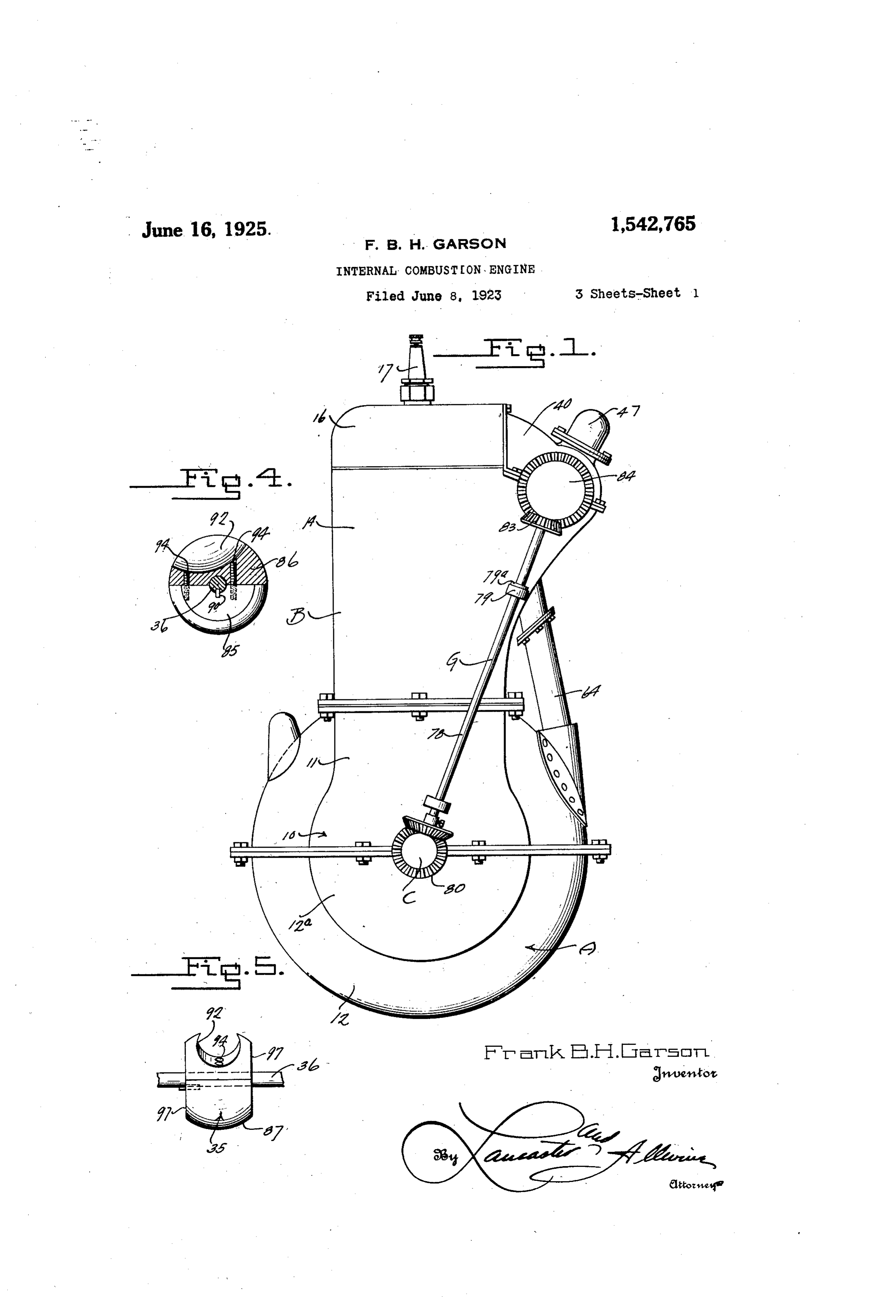
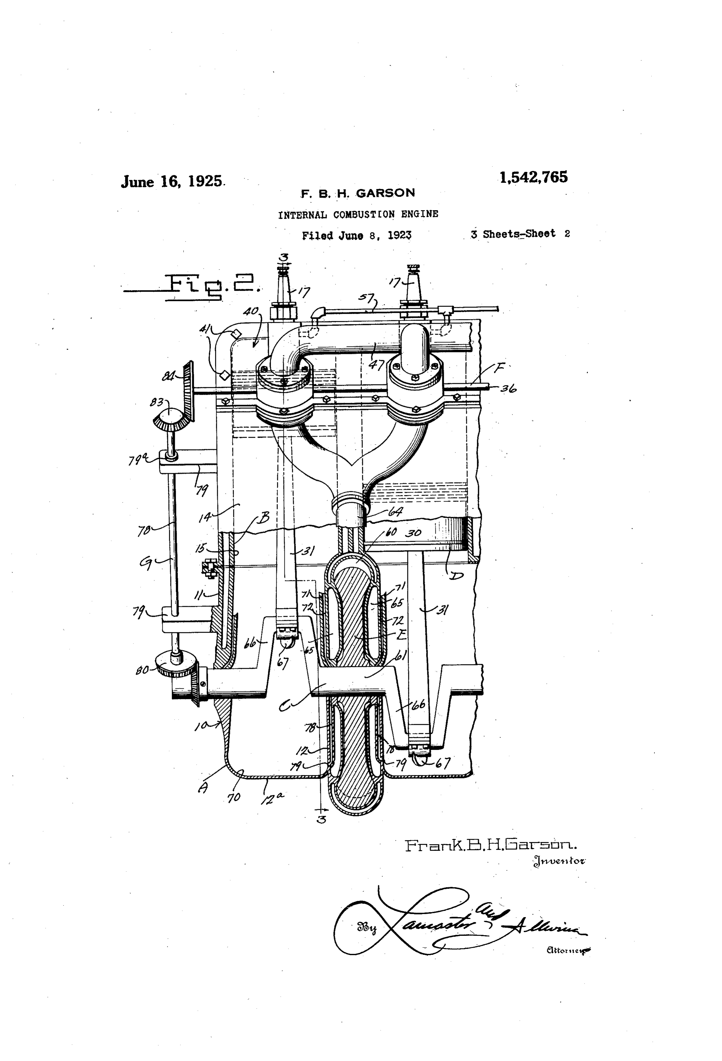
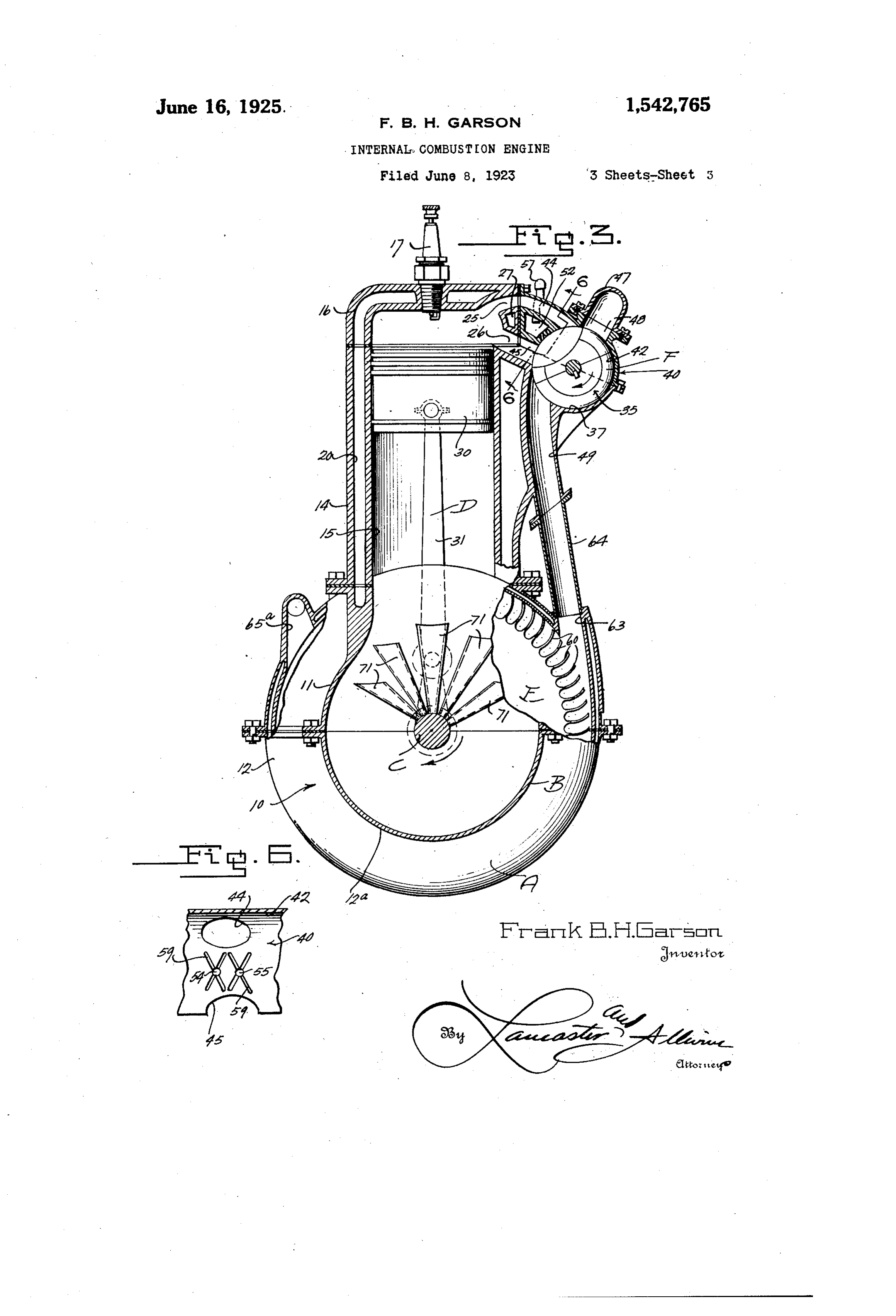
To all whom it may concern bodiment of this invention, the letter A Be it known that I, FRANK B. H. GARson, may generally designate the internal com a citizen of the United States, residing at bustion engine, which may include a hous Lawrence, in the county of Essex and State ing construction B; crank shaft C, piston 60 of Massachusetts, have invented certain new means D for operating the crank shaft C; and useful Improvements in Internal-Com a turbine E connected to the crank shaft C, bustion Engines, of which the following is rotary valve means F for control of intake a specification. w and exhaust gases, and means G for drive This invention relates to improvements of the valve F by the crank shaft C. 65 O in internal combustion engines. Referring to the housing B, the same may The primary object of this invention is include a sectional crankcase 10, including the provision of an internal combustion en as parts thereof upper and lower crank case gine in which the expansion and explosive portions 11 and 12, which embody novel qualities of a fuel used therein are utilized casings 12 for the accommodation of the 70 5 to the maximum extent for power genera turbines E to be subsequently described. tion. - The cylinder block 14 is provided as a part A further object of this invention is the of the housing B, within which the cylinder provision of a novel type of rotary valve chambers 15 are formed in any desired num control for the intake and exhaust of fuel ber according to the type of engine desired. 20 charges of internal combustion engines. A detachable cylinder head 16 is also pro A further object of this invention is the vided, in the top whereof the detachable provision of means for utilizing exhaust spark plugs 17 may fit. It is preferred that gases after their escape from the internal the engine A be of the water cooled type, combustion engine cylinder chambers, con and to this end water compartments 20 are 25 veying them to a turbine operatively con provided about the cylinder chambers 15 as nected to the internal combustion engine in ordinary construction. For each cylin crank shaft where their complete forces may der of the internal combustion engine, in be used in the generation of power. take and exhaust ports 25 and 26 respec 85 Other objects and advantages of this in tively are provided in the cylinder blocks 30 vention will be apparent during the course or heads 14 and 16, to one side of the inter of the following detailed description. nal combustion engine; said intake and ex In the accompanying drawings, forming haust ports or passageways communicating a part of this specification, and wherein with the rotary valve means F to be subse similar reference characters designate cor quently described. Between the intake and 35 responding parts throughout the several exhaust ports 25 and 26 of each cylinder Views. chamber, the water passage 27 is provided. Figure 1 is an end elevation of an inter The crank shaft C is of any approved type, nal combustion engine constructed in ac and is preferably supported intermediate cordance with features of this invention. sections 11 and 12 of the crank case 10. 95 40 Figure 2 is a fragmentary view, partly in The piston means D may include the ordi section, and partly in side elevation, show nary pistons 30 operating within the cylin in Figure
Ey. features of this invention. der 15, and connected with the throws of 3 is a transverse cross sectional the crank shaft as by means of the connect view, taken through the internal combus ing rods 31.
45 tion engine substantially on the line 3-3
Referring to the construction of the in of Figure 2. - ternal combustion engine housing B, for Figures 4 and 5 are views showing the the accommodation of the rotary valve con construction of a rotary valve employed in trol, it is preferred to provide a complete the internal combustion engine for the con rotary valve 35 for each cylinder of the 05 50 trol of fuel intake and exhaust gases. internal combustion engine; said rota Figure 6 is a fragmentary view, illustrat valves being mounted upon a shaft 36, whic ing a valve seating surface, showing more extends longitudinally of the motor and is particularly the means for feeding lubri operated from the crank shaft C by means
cant to the valve. - of the transmission G to be subsequently 110 In the drawings, wherein for the purpose described. The cylinder block 14 of the of illustration is shown the preferred em housing B is preferably provided with a
Page 5
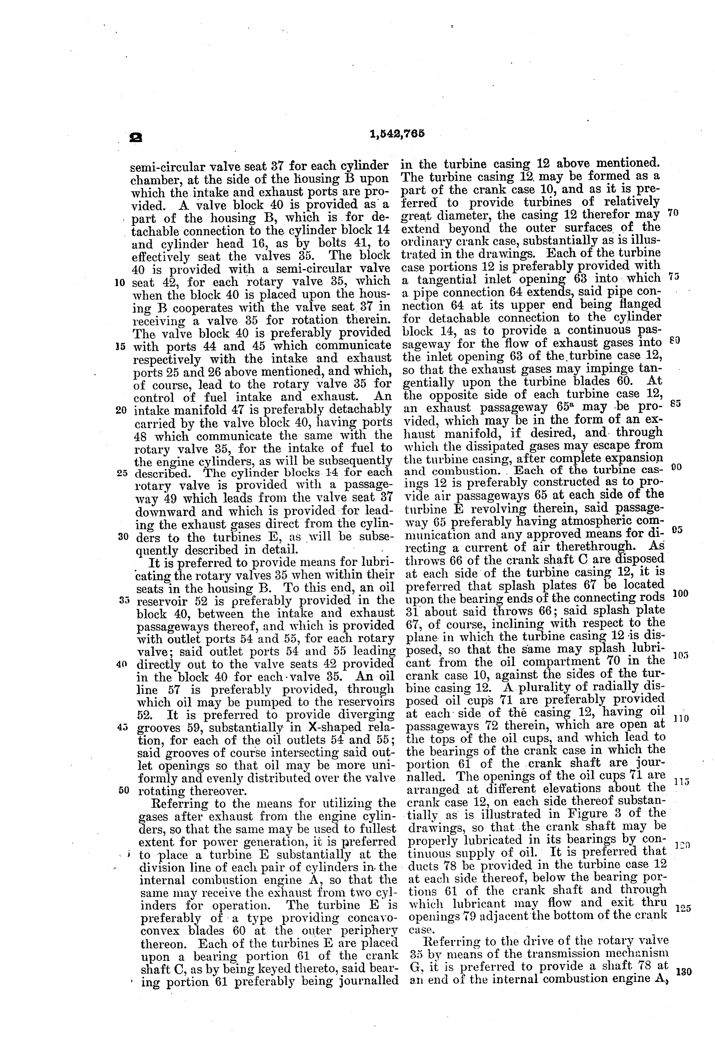
semi-circular valve seat 37 for each cylinder in the turbine casing 12 above mentioned. chamber, at the side of the housing B upon The turbine casing 12 may be formed as a which the intake and exhaust ports are pro part of the crank case 10, and as it is pre vided. A valve block 40 is provided as a ferred to provide turbines of relatively 70 part of the housing B, which is for de great diameter, the casing 12 therefor may extend beyond the outer surfaces of the tachable connection to the cylinder block 14 ordinary and cylinder head 16, as by bolts 41, to crank case, substantially as is illus effectively seat the valves 35. The block case trated in the drawings. Each of the turbine 40 is provided with a semi-circular valve portions 12 is preferably provided with 5 0. seat 42, for each rotary valve 35, which a tangential inlet opening 63 into , which when the block 40 is placed upon the hous a pipe connection 64 Eis, said pipe con ing B cooperates with the valve seat 37 in nection 64 at its upper end being flanged receiving a valve 35 for rotation therein. for detachable connection to the cylinder The valve block 40 is preferably provided block 14, as to provide a continuous pas 80 5 with ports 44 and 45 which communicate sageway for the flow of exhaust gases into respectively with the intake and exhaust the inlet opening 63 of the turbine case 12, so that the exhaust gases may impinge tan ports 25 and 26 above mentioned, and which, gentially upon the turbine blades 60. At of course, lead to the rotary valve 35 for control of fuel intake and exhaust. An the opposite side of each turbine case 12, 20 intake manifold 47 is preferably detachably an exhaust passageway 65 may be pro carried by the valve block 40, having ports vided, which may be in the form of an ex 48 which communicate the same with the haust manifold, if desired, and through rotary valve 35, for the intake of fuel to which the dissipated gases may escape from the engine cylinders, as will be subsequently the turbine casing, after complete expansion 00 described. The cylinder blocks. 14 for each and combustion. Each of the turbine cas rotary valve is provided with a passage ings 12 is preferably constructed as to pro way 49 which leads from the valve seat 37 vide air Epassageways 65 at each side of the downward and which is provided for lead turbine revolving therein, said passage ing the exhaust gases direct from the cylin way 65 preferably having atmospheric com 30 ders to the turbines E, as will be subse munication and any approved means for di quently described in detail. recting a current of air therethrough. As It is preferred to provide means for lubri throws 66 of the crank shaft C are disposed cating the rotary valves 35 when within their at each side of the turbine casing 12, it is preferred that splash plates 67 be located 00 seats in the housing B. To this end, an oil 35 reservoir 52 is preferably provided in the upon the bearing ends of the connecting rods block 40, between the intake and exhaust 31 about said throws 66; said splash plate passageways thereof, and which is provided 67, of course, inclining with respect to the with outlet ports 54 and 55, for each rotary plane in which the turbine casing 12 is dis posed, so that the same may splash lubri valve; said outlet ports 54 and 55 leading cant from the oil compartment 70 in the directly out to the valve seats 42 provided in the block 40 for each. valve 35. An oil crank case 10, against the sides of the tur line 57 is preferably provided, through bine casing 12. A plurality of radially dis which oil may be pumped to the reservoirs at eachoilside posed cups 71 are preferably provided of the casing 12, having oil 10 52. It is preferred to provide diverging 45 grooves 59, substantially in X-shaped rela passageways 72 therein, which are open at tion, for each of the oil outlets 54 and 55; the tops of the oil cups, and which lead to said grooves of course intersecting said out the bearings of the crank case in which the let openings so that oil may be more uni portion 61 of the crank shaft are jour formly and evenly distributed over the valve nalled. The openings of the oil cups 71 are rotating thereover. arranged at different elevations about the Referring to the means for utilizing the crank case 12, on each side thereof substan gases after exhaust from the engine cylin tially as is illustrated in Figure 3 of the drawings, so that the crank shaft may be ders, so that the same may be used to fullest properly lubricated in its bearings by con li) extent for power generation, it is preferred tinuous supply of oil. It is preferred that to place a turbine E substantially at the ducts 78 be provided in the turbine case 12 division line of each pair of cylinders in the at each side thereof, below the bearing por internal combustion engine A, so that the tions 61 of the crank shaft and through Sane may receive the exhaust from two cyl which lubricant may flow and exit thru inders for operation. The turbine E is preferably of a type providing concavo CS. openings 79 adjacent the bottom of the crank 125 convex blades 60 at the outer periphery Referring to the drive of the rotary valve thereon. Each of the turbines E are placed upon a bearing portion 61 of the crank 35 by means of the transmission mechanism shaft C, as by being keyed thereto, said bear G, it is preferred to provide a shaft 78 at 30 ing portion 61 preferably being journalled an end of the internal combustion engine A
Page 6
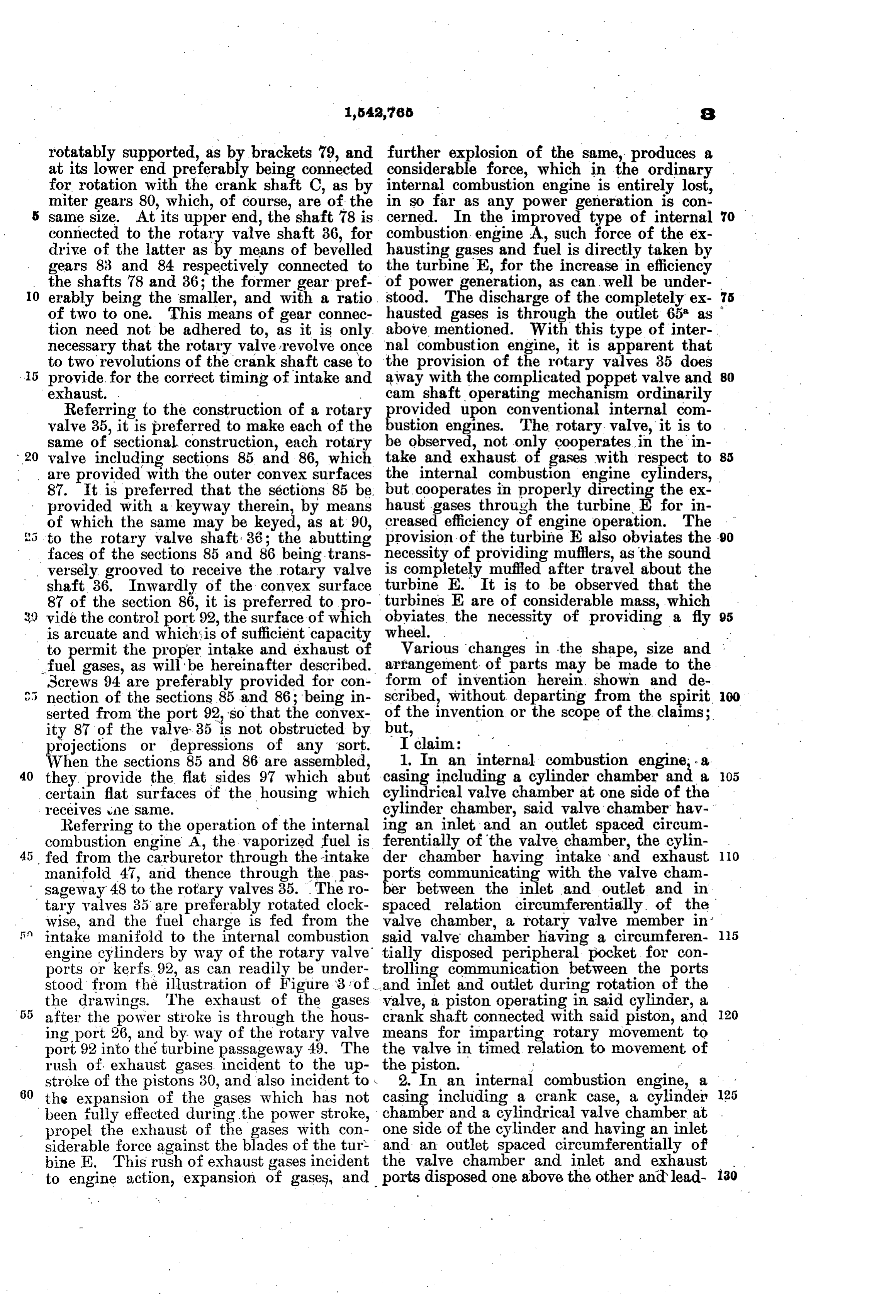
rotatably supported, as by brackets 79, and further explosion of the same, produces a at its lower end preferably being connected considerable force, which in the ordinary for rotation with the crank shaft C, as by internal combustion engine is entirely lost, miter gears 80, which, of course, are of the in so far as any power generation is con same size. At its upper end, the shaft 78 is cerned. In the improved type of internal 70 connected to the rotary valve shaft 36, for combustion engine A, such force of the ex drive of the latter as by means of bevelled hausting gases and fuel is directly taken by gears 83 and 84 respectively connected to the turbine E, for the increase in efficiency the shafts is and 36; the former gear pref of power generation, as can well be under O erably being the smaller, and with a ratio. stood. The discharge of the completely ex 75 of two to one. This means of gear connec hausted gases is through the outlet 65 as tion need not be adhered to, as it is only above mentioned. With this type of inter necessary that the rotary valve revolve once nal combustion engine, it is apparent that to two revolutions of the crank shaft case to the provision of the rotary valves 35 does 80 provide for the correct timing of intake and away with the complicated poppet valve and exhaust. . camshaft operating mechanism ordinarily Referring to the construction of a rotary provided upon conventional internal com valve 35, it is preferred to make each of the bustion engines. The rotary, valve, it is to . same of sectional construction, each rotary be observed, not onl cooperates in the in 20 valve including sections 85 and 86, which take and exhaust o gases with respect to 85 are provided with the outer convex surfaces the internal combustion engine cylinders, 87. It is preferred that the sections 85 be. but cooperates in properly directing the ex provided with a keyway therein, by means haust gases through the turbine, for in of which the same may be keyed, as at 90, creased efficiency of engine operation. The to the rotary valve shaft 36; the abutting provision of the turbine E also obviates the -90 faces of the sections 85 and 86 being trans necessity of providing mufflers, as the sound versely grooved to receive the rotary valve is completely muffled after travel about the shaft 36. Inwardly of the convex surface turbine E. It is to be observed that the 87 of the section 86, it is preferred to pro- turbines E are of considerable mass, which 95 obviates the necessity of providing a fly vide the control port 92, the surface of which wheel.
is arcuate and which is of sufficient capacity to permit the proper intake and exhaust of Various changes in the shape, size and arrangement of parts may be made to the fuel gases, as will be hereinafter described. form
Screws 94 are preferably provided for con of invention herein. shown and de nection of the sections 85 and 86; being in scribed, without departing from the spirit. OO serted from the port 92, so that the convex of the invention or the scope of the claims; ity 87 of the valve 35 is not obstructed by but, projections or depressions of any sort. I claim:
When the sections 85 and 86 are assembled, 1. In an internal combustion engine, a
they provide the flat sides 97 which abut casing including a cylinder chamber and a certain flat surfaces of the housing which cylindrical valve chamber at one side of the receives the same. W cylinder chamber, said valve chamber hav Referring to the operation of the internal ing an inlet and an outlet spaced circum combustion engine A, the vaporized fuel is ferentially of the valve chamber, the cylin 10 fed from the carburetor through the intake der chamber having intake and exhaust manifold 47, and thence through the pas orts communicating with the valve cham sageway 48 to the rotary valves 35. The ro er between the inlet and outlet and in tary valves 35 are preferably rotated clock spaced relation circumferentially of the wise, and the fuel charge is fed from the valve chamber, a rotary valve member in is in intake manifold to the internal combustion said valve chamber having a circumferen 15 engine cylinders by way of the rotary valve tially disposed peripheral pocket for con ports or kerfs. 92, as can readily be under trolling communication between the ports stood from the illustration of Figure 3 of . and inlet and outlet during rotation of the the drawings. The exhaust of the gases valve, a piston operating in said cylinder, a 20 after the power stroke is through the hous crank shaft connected with said piston, and ing port 26, and by way of the rotary valve means for imparting rotary movement to port 92 into the turbine passageway 49. The the valve in timed relation to movement of rush of exhaust gases incident to the up the piston. - stroke of the pistons 30, and also incident to . 2. In an internal combustion engine, 60 the expansion of the gases which has not casing including a crank case, a cylinder 125
been fully effected during the power stroke, chamber and a cylindrical valve chamber at . propel the exhaust of the gases with con one side of the cylinder and having an inlet siderable force against the blades of the tur and an outlet spaced circumferentially of bine E. This rush of exhaust gases incident the valve chamber and inlet and exhaust 130 to engine action, expansion of gases, and ports disposed one above the other and lead
Page 7
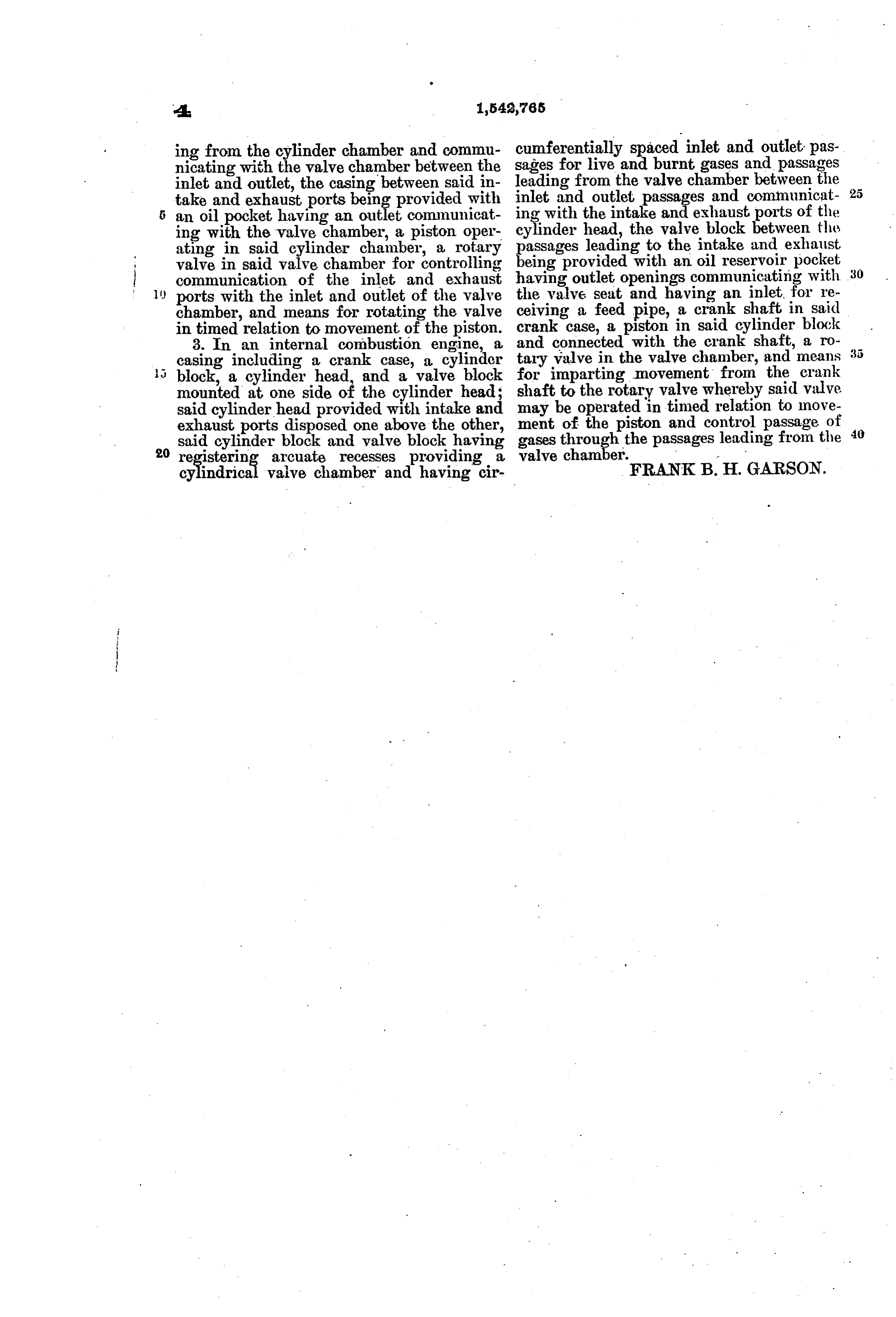
ing from the cylinder chamber and commu sages cumferentially spaced inlet and outlet pas nicating with the valve chamber between the leadingforfrom live and burnt gases and passages the valve chamber between the inlet and outlet, the casing between said in take and exhaust ports being provided with inlet and outlet passages and communicat 25 an oil pocket having an outlet communicat ing with the intake and exhaust ports of the ing with the valve chamber, a piston oper cylinder head, the valve block between the ating in said cylinder chamber, a rotary passages leading to the intake and exhaust valve in said valve chamber for controlling being provided with an oil reservoir pocket communication of the inlet and exhaust having outlet openings communicating with 30 ports with the inlet and outlet of the valve the valve seat and having an inlet, for re chamber, and means for rotating the valve ceiving a feed pipe, a crank shaft in said in timed relation to movement of the piston. andcrankcase, a piston in said cylinder block 8. In an internal combustion engine, a connected with the crank shaft, a ro casing including a crank case, a cylinder tary valve in the valve chamber, and means block, a cylinder head, and a valve block for imparting movement from the crank mounted at one shaft to the rotary valve whereby said valve said cylinder headside of the with provided cylinder, intakehead;
and may be operated in timed relation to move exhaust ports disposed one above the other, ment of the piston and control passage of said cylinder block and valve block having gases Ethe passages leading from the 20 registering arcuate recesses providing a valve chamber.
cylindrical valve chamber and having cir FRANKB. H. GARSON.
Provenance
- Collection
- Cited prior art
- Original PDF
- patentimages.storage.googleapis.com →
- Filed
- 1923-06-08
- Pages
- 7
- Method
- pdftotext (the PDF's own text layer) + pdftoppm 300dpi page scans
- Source
- Google Patents bibliographic record
- Granted
- 1925-06-16
- Inventors
- Frank B H Garson
- Transcribed from
- patentimages.storage.googleapis.com →