patent · US11505459B1
Processes for producing hydrogen
22 November 2022
Page 1 — bibliographic record
( 12 ) United States Patent ( 10 ) Patent No.: US 11,505,459 B1 Nagel et al . (45 ) Date of Patent : Nov. 22 , 2022 ( 54 ) PROCESSES FOR PRODUCING HYDROGEN ( 58 ) Field of Classification Search
( 71 ) Applicant: Alpha Portfolio LLC , Naples , FL (US) B01J 2219/0803 ; B01J 2219/0869 ; B01J ( 72 ) Inventors: Christopher J. Nagel , Wayland , MA 19/12 ; B01J 2219/0849 ; B01J 2219/0854 ; (US ) ; Stephen P. Lemoi , Johnston, RI B01J 2219/0877 ; B01J 2219/12 ; YO2E (US ) ; Mark G. Janson , Swansea, MA 60/364 ; YO2E 60/36 (US ) See application file for complete search history . ( 73 ) Assignee: Alpha Portfolio LLC , Naples, FL ( US ) (56 ) References Cited
( * ) Notice: Subject to any disclaimer, the term of this U.S. PATENT DOCUMENTS patent is extended or adjusted under 35 5,149,407 A * 9/1992 Meyer CO1B 3/042 U.S.C. 154 ( b ) by 0 days. 204/ 157.52
* cited by examiner
Primary Examiner - Xiuyu Tai ( 51 ) Int . Ci . (74 ) Attorney , Agent, or Firm — Elmore Patent Law COIB 3/00 ( 2006.01 ) Group, P.C .; Carolyn S. Elmore ; Joseph C. Zucchero
BOIJ 19/08 ( 2006.01 ) ( 57 ) ABSTRACT (52) U.S. CI. The invention includes apparatus and methods for instanti CPC C01B 3/26 ( 2013.01 ) ; B013 19/087 ating hydrogen in a nanoporous carbon powder.
2219/0869 (2013.01 ) 21 Claims , 21 Drawing Sheets
Page 2
Drawing sheet — no readable text.
Page 3
Drawing sheet — no readable text.
Page 4
Drawing sheet — no readable text.
Page 5
Drawing sheet — no readable text.
Page 6
Drawing sheet — no readable text.
Page 7
Drawing sheet — no readable text.
Page 8
Drawing sheet — no readable text.
Page 9
Drawing sheet — no readable text.
Page 10
Drawing sheet — no readable text.
Page 11
Drawing sheet — no readable text.
Page 12
Drawing sheet — no readable text.
Page 13
Drawing sheet — no readable text.
Page 14
Drawing sheet — no readable text.
Page 15
Drawing sheet — no readable text.
Page 16
Drawing sheet — no readable text.
Page 17
Drawing sheet — no readable text.
Page 18
Drawing sheet — no readable text.
Page 19
Drawing sheet — no readable text.
Page 20
Drawing sheet — no readable text.
Page 21
Drawing sheet — no readable text.
Page 22
Drawing sheet — no readable text.
Page 23
PROCESSES FOR PRODUCING HYDROGEN sufficient to allow a gas to permeate into the reactor chamber and contain a nanoporous carbon material;
BACKGROUND OF THE INVENTION ( c ) A reactor head space disposed above the reactor cap ; ( d) 1 , 2 , 3 , 4 , 5 or more RA coils surrounding the reactor
Processes for producing hydrogen , including hydrogen on 5 chamber and / or reactor head space operably connected demand systems , are described . For example, electrolyzers to one or more RA frequency generators and / or one or including a proton -exchange membrane, a cathode disposed more power supplies;
on one surface, and an anode on a second surface of the ( e ) 0 , 1 , 2 , 3 , 4 , 5 or more pairs of RA lamps wherein the membrane have been used . Such an anode can include an 10 pairs of RA lamps are disposed circumferentially ionomer binder with dispersed particles having a core and around the RA coils and define a space between the catalytic layer, such as iridium or platinum . However, such pairs of RA lamps and the RA coils , when present ; systems can be characterized by high pressures and / or ( f) An optional x - ray source configured to expose the reactor chamber to X -rays;
water - saturated gas . Therefore, there is aa benefit to improv ( g ) One or more optional lasers configured to direct aa laser ing such processes to produce dry or substantially dry 15 towards ( e.g. , through or across) the reactor chamber or hydrogen gas . the gas within the reactor assembly, when present; and
SUMMARY OF THE INVENTION
(h) A computer processing unit ( CPU) configured to control the power supply, frequency generator, X -ray source, lamps and /or lasers.
The present invention relates to the discovery that appa- 20 As will be described in more detail below, the gas inlet of ratuses containing carbon matrices can be used to produce the reactor assembly can be in fluid connection with at least hydrogen . The processes of the invention include the appli one gas supply selected from the group consisting of air, cation of electromagnetic radiation , directly and / or indi- oxygen , hydrogen , helium , nitrogen , neon , argon , krypton , rectly, to gases , nano -porous carbon , or compositions and xenon , carbon monoxide, carbon dioxide and mixtures combinations thereof, thereby pre -treating the gas , and 25 thereof; and / or ( iii ) the gas supply is directed through a gas exposing a carbon matrix to pre -treated gas in an apparatus manifold controlled by mass flow meters . of the invention and recovering hydrogen produced therein . As will be described in more detail below, the nanoporous The invention relates to apparatuses for instantiating carbon powder charged to the reactor assembly can com materials and processes for using such apparatuses. prise graphene having at least 95 % wt . carbon (metals The invention includes processes comprising the steps of 30 basis ) , a mass mean diameter between 1 um and 5 mm , and contacting a bed comprising nanoporous carbon with an an ultramicropore surface area between about 100 and 3000 activated gas while applying electromagnetic radiation to the m?/g . The nanoporous carbon powder is preferably charac nanoporous carbon for a time sufficient to cause instantiation terized by acid conditioning, wherein the acid is selected of hydrogen and collecting the hydrogen. The invention from the group consisting of HCI , HF, HBr, HI , sulfuric acid , further relates to the hydrogen produced by the process . 35 phosphoric acid , carbonic acid, and nitric acid , and a More specifically, the invention includes a process of residual water content of less than that achieved upon instantiating hydrogen within a nanoporous carbon powder exposure to a relative humidity (RH ) of less than 40 % RH comprising the steps of: at room temperature . In a preferred embodiment, the process (i ) adding a nanoporous carbon powder into a reactor contemplates degassing the nanoporous carbon powder prior assembly (RA ), as described below , 40 to the process .
( ii ) adding a first gas composition to the reactor assembly ; As will be described in more detail below, the reactor (iii ) powering one or more RA coils to a first electromag- assembly can include a plurality of devices that can impart netic energy level ; electromagnetic fields, including X - ray sources , coils , lasers (iv ) subjecting the nanoporous carbon powder (the terms and lamps or lights, including pencil lamps, short wave and nanoporous carbon powder, nanoporous carbon material and 45 long wave lamps. The wavelengths generated by each device nanoporous carbon are used herein interchangeably) to (e.g. , lamps or lasers ) can be independently selected . harmonic patterning to instantiate hydrogen thereby produc- As will be described in more detail below, the RA coils ing a product gas composition ; can be made from the same or different electrically con ( v ) collecting the product gas composition and optionally ducting materials . For example, a first RA coil comprises a separating hydrogen . 50 copper wire winding, a second RA coil comprises a braiding In one embodiment, the RA coil surrounds a nanoporous of copper wire and silver wire , and a third RA coil is a carbon bed to establish a harmonic electromagnetic reso- platinum wire winding and each RA coil is configured to nance in ultramicropores of the nanoporous carbon powder. create a magnetic field and wherein each power supply The first gas composition can be , for example, air, oxygen , independently provides AC and / or DC current . hydrogen, helium , nitrogen, neon , argon , krypton, xenon , 55 As will be described in more detail below, the reactor carbon monoxide , carbon dioxide or mixtures thereof, pref- assembly can be characterized by (i ) a first pair of RA lamps erably nitrogen or air. Preferably, the nanoporous carbon configured in a first plane defined by a center axis and a first powder comprises graphene having at least 99.9 % wt . radius of the reactor chamber, (ii ) a second pair of RA lamps carbon (metals basis ) , a mass mean diameter between 1 um configured in a second plane defined by the center axis and and 5 mm , and an ultramicropore surface area between about 60 a second radius of the reactor chamber and (iii ) aa third pair 100 and 3000 m²/g . of RA lamps configured in aa third plane defined by the center More specifically, the invention includes a reactor assem- axis and a third radius of the reactor chamber. Preferably, bly comprising: each RA lamp is a pencil lamp characterized by a tip (a ) A reactor chamber containing a nanoporous carbon substantially equidistant from the central axis anda each pair material; 65 of RA lamps comprises a vertical RA lamp and a horizontal ( b ) A second porous frit defining the ceiling of the reactor RA lamp. Preferably each pair of lamps is equidistantly chamber; wherein each porous frit has a porosity that is spaced around the circumference of the reactor chamber.
Page 24
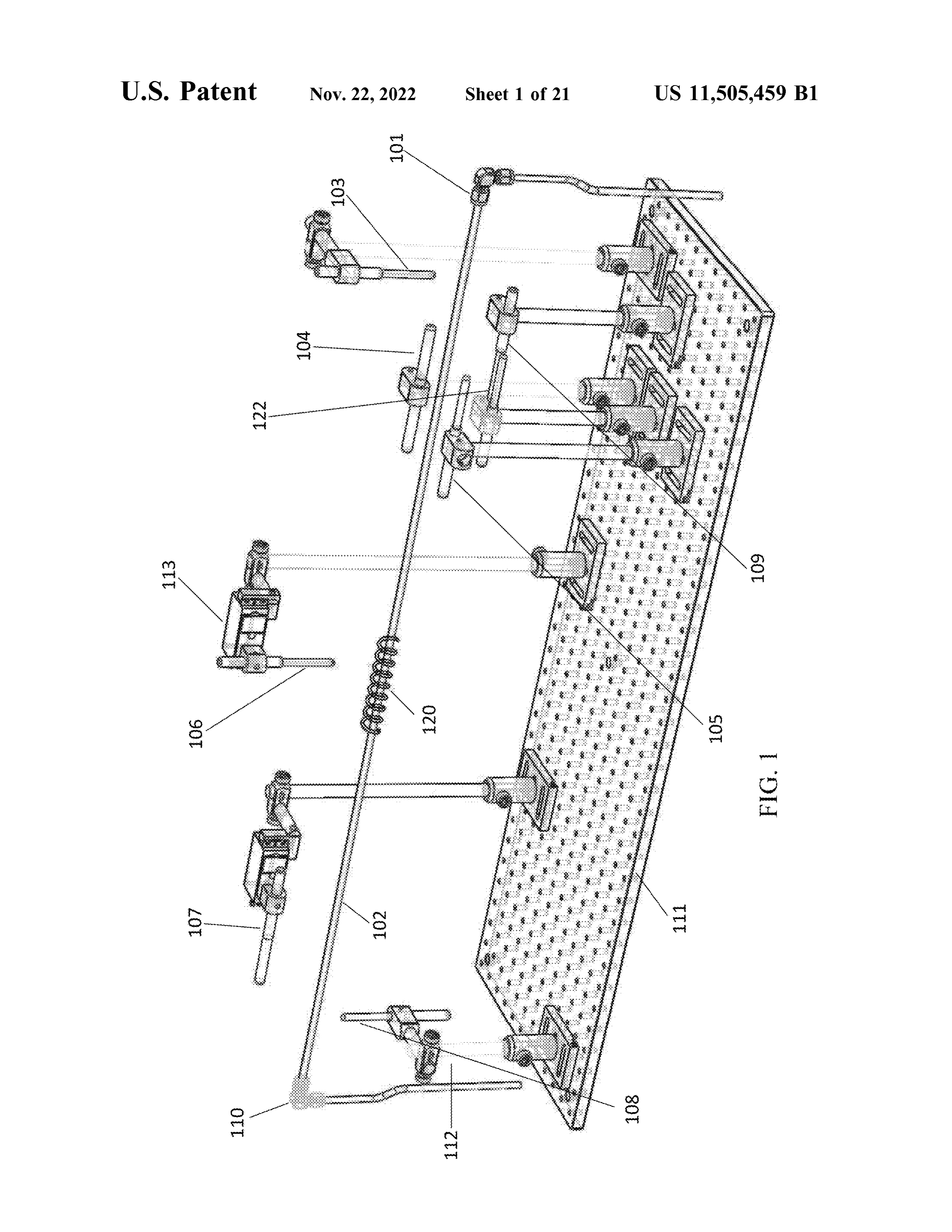
As will be described in more detail below , the reactor The foregoing and other objects, features and advantages assembly further comprises an electromagnetic embedding of the invention will be apparent from the following more enclosure (E/ MEE or EMEE ) , as defined more specifically particular description of preferred embodiments of the below. The E /MEE is typically located along a gas line invention, as illustrated in the accompanying drawings in upstream of the reactor assembly gas inlet . Typically, an 5 which like reference characters refer to the same parts electromagnetic embedding enclosure located upstream of throughout the different views . The drawings are not nec the gas inlet comprises : essarily to scale , emphasis instead being placed upon illus ( a ) a gas inlet; trating the principles of the invention . ( b ) at least one E/ MEE pencil lamp positioned below the FIG . 1 is a perspective view of an E/MEE of the inven internal gas line , at least one E/ MEE pencil lamp 10 tion .
positioned above the internal gas line and at least one
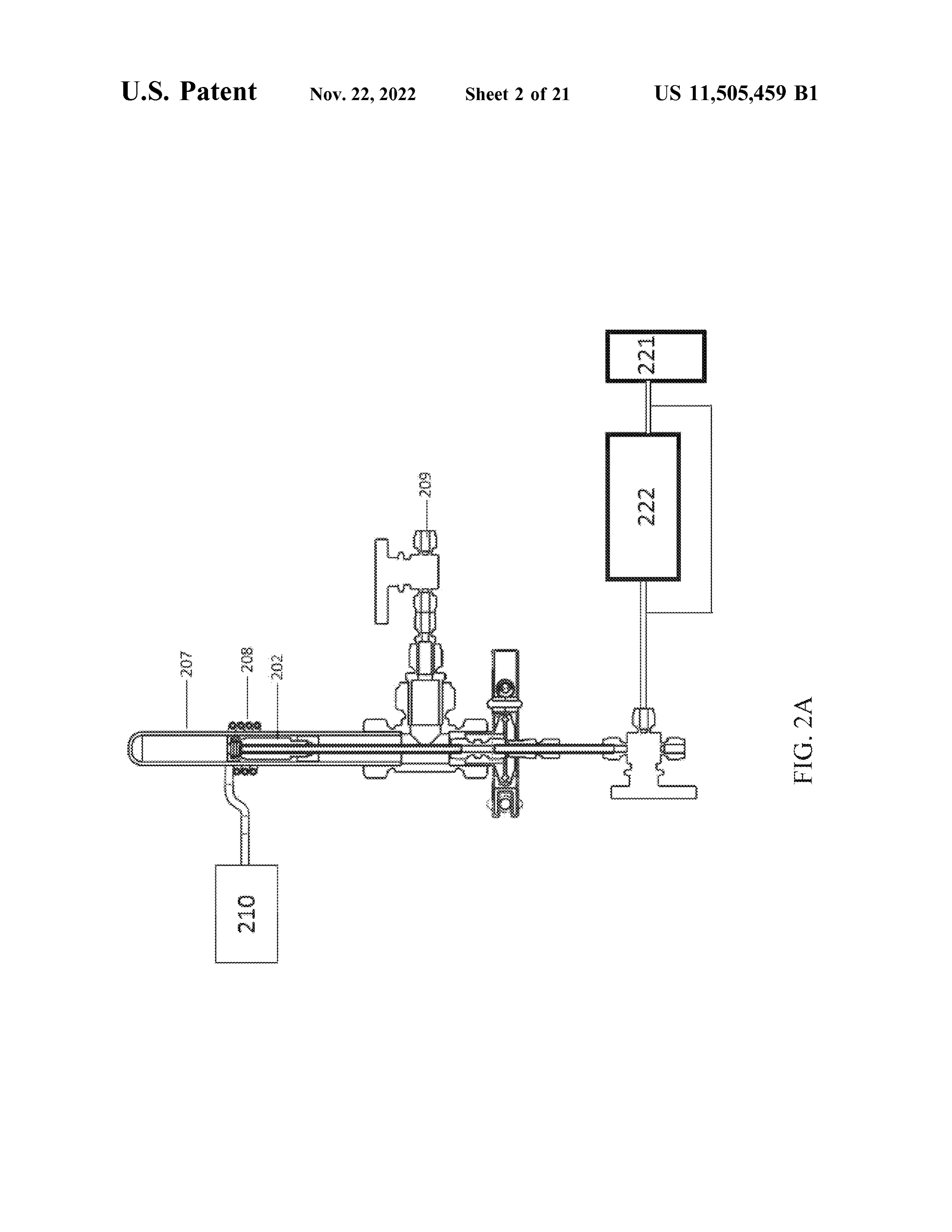
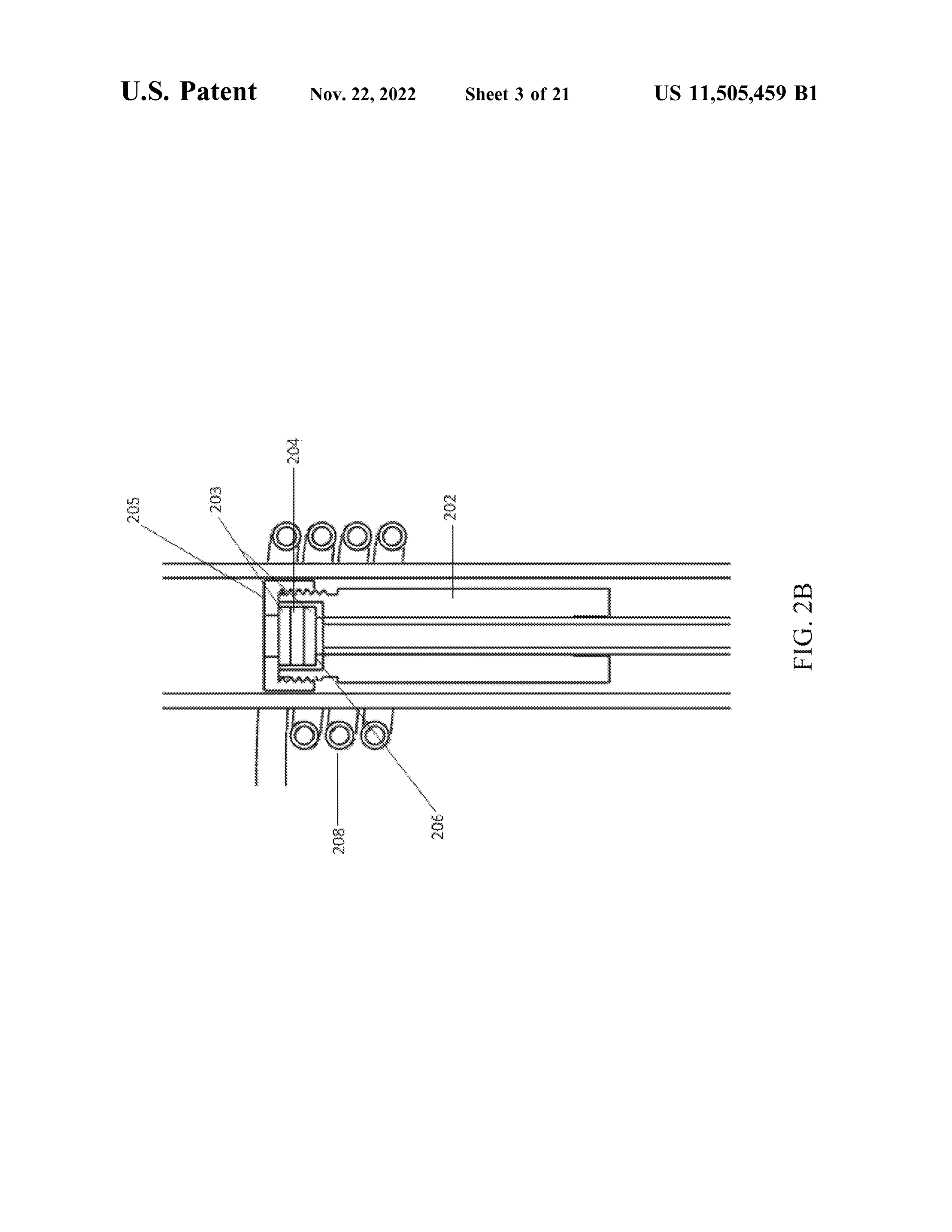
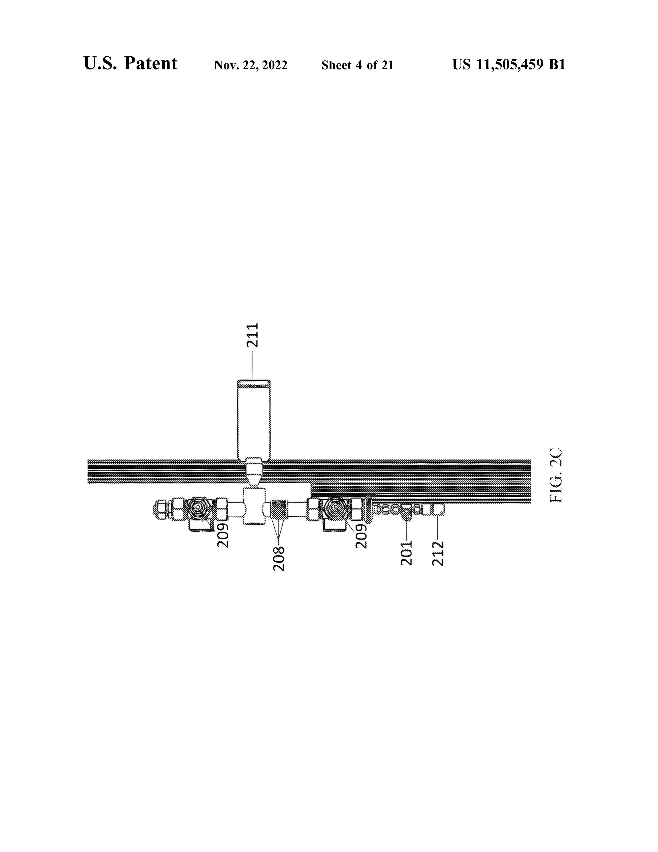
E/MEE pencil lamp positioned to the side of the FIGFIGS . 2B . 2A and 2C show reactor assembly components .
is an expanded view of the reactor assembly internal gas line; components of FIG . 2A .
wherein each E/MEE pencil lamp is independently rotat ably mounted, located along the length of the internal 15 provides five FIG
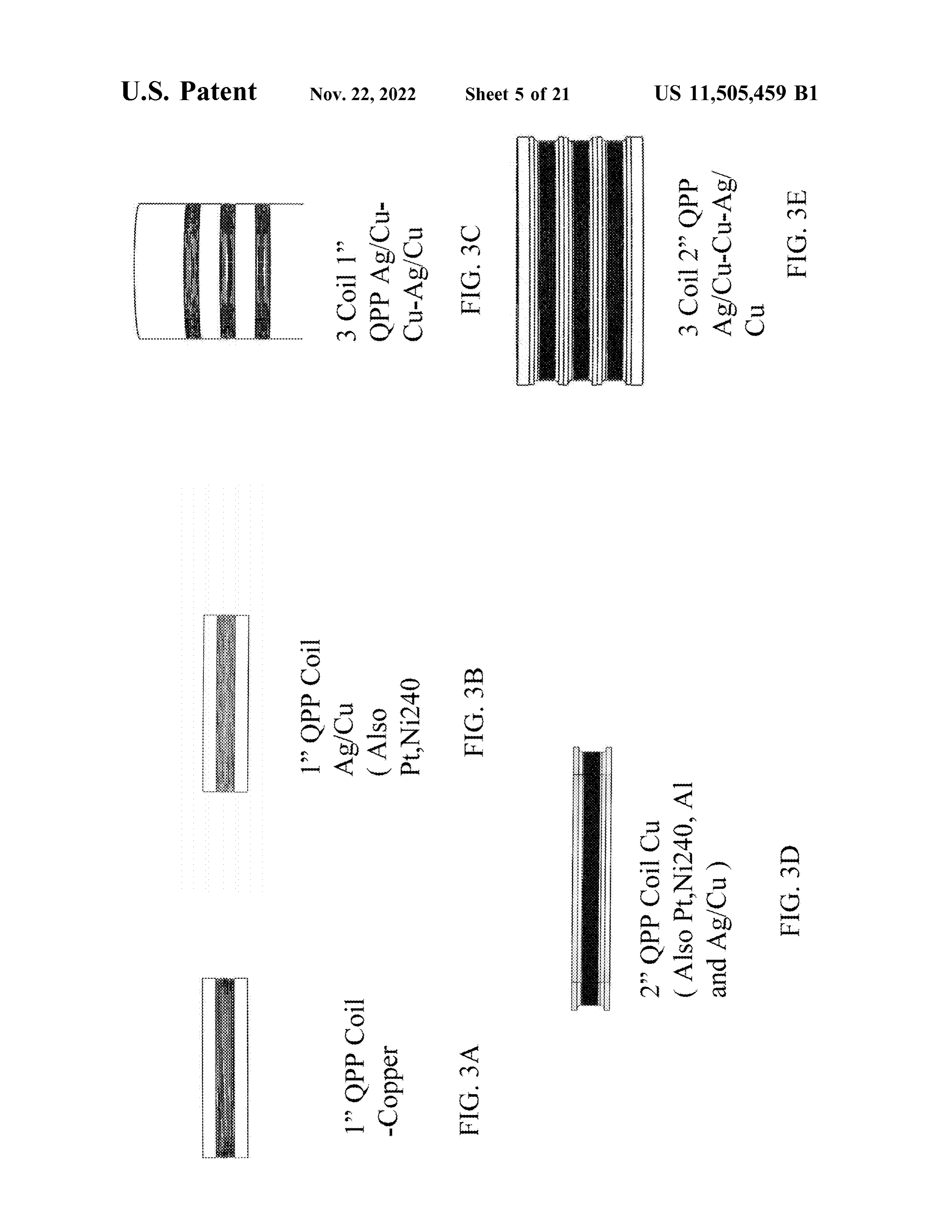
views of coils which can be used in a reactor gas line, and the lamps and / or coil ( s ) are powered by a power supply, assembly.
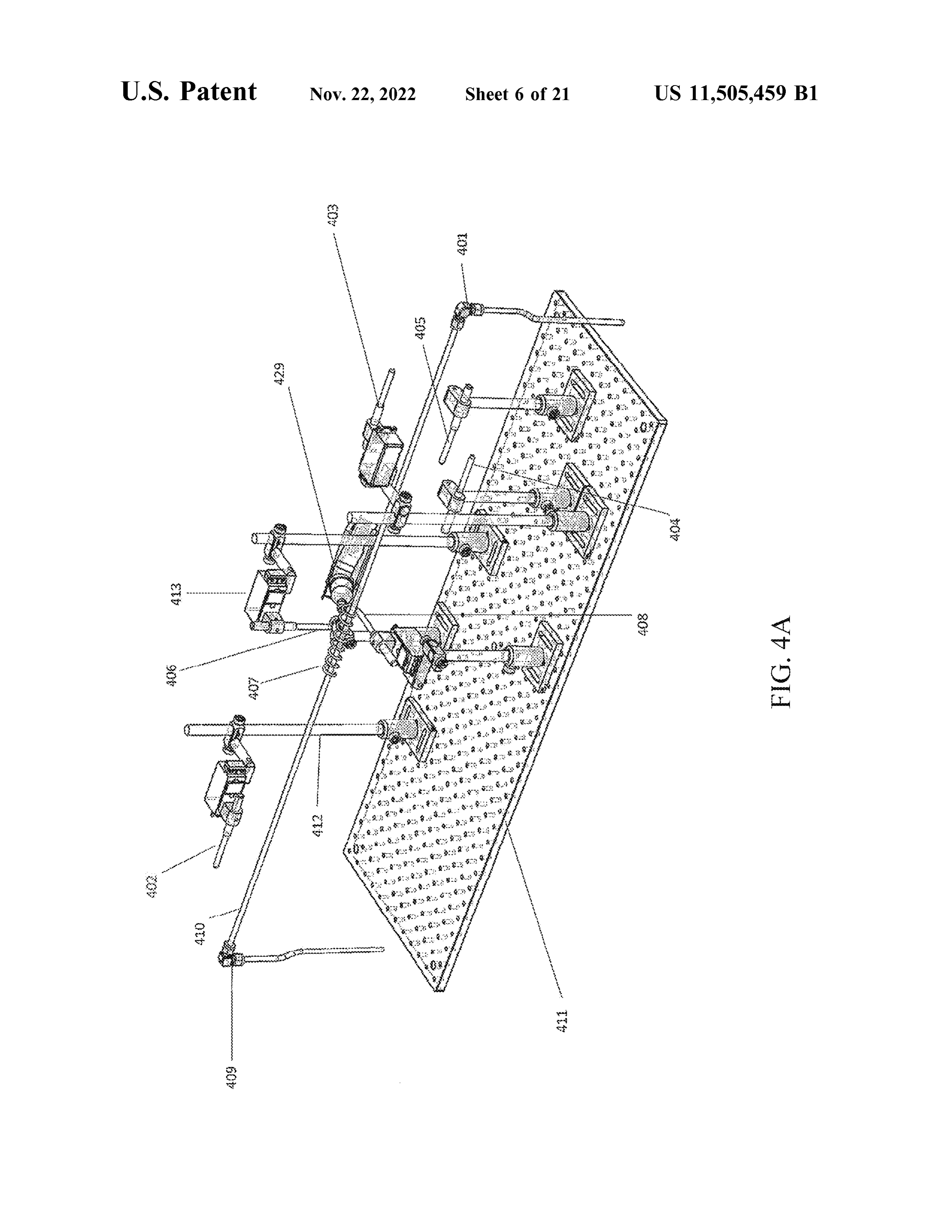
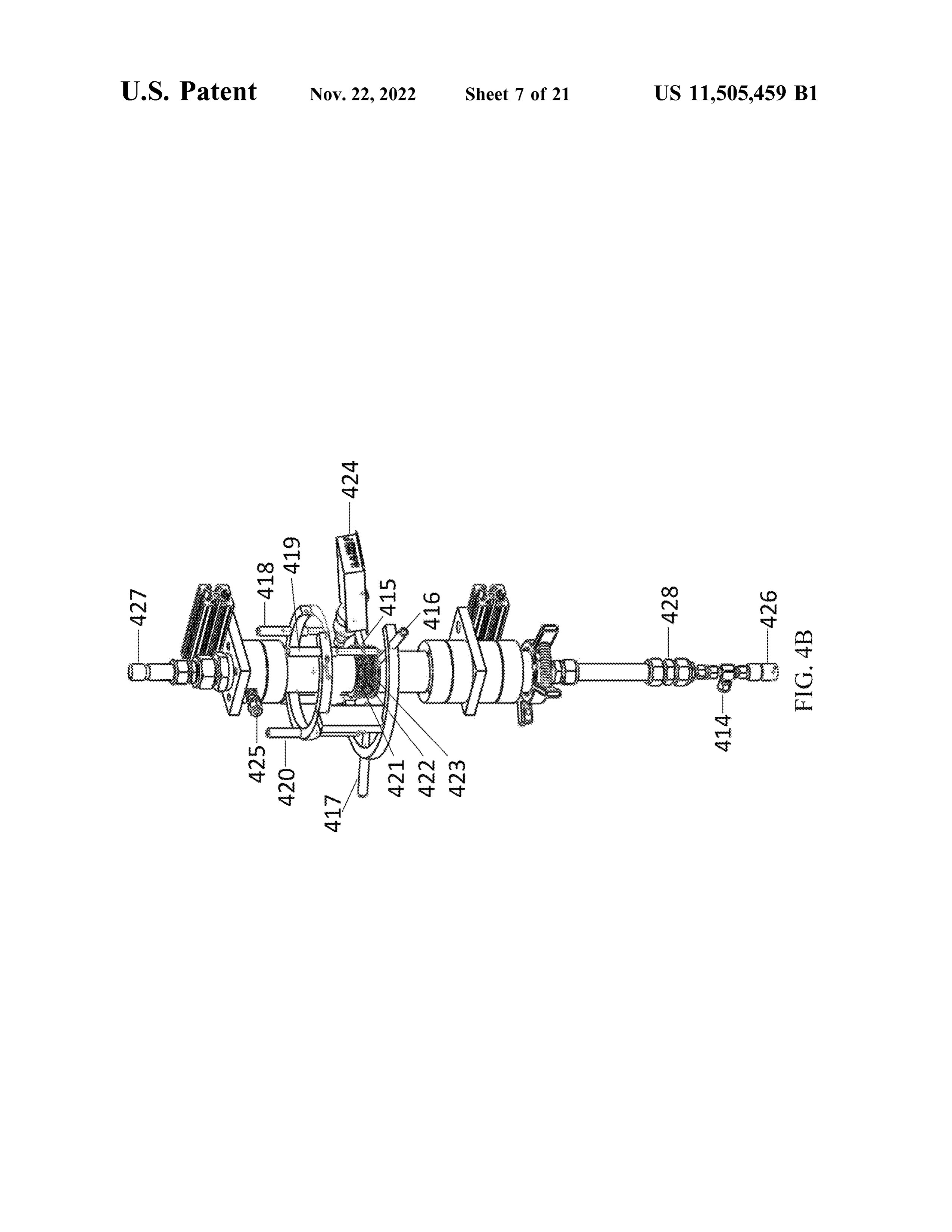
preferably the power supply of the reactor assembly ; FIG . 4A is a perspective view of an E /MEE of the the gas flow , lamps and / or coil ( s ) are preferably indepen invention used in carbon pretreatment. FIG . 4B shows dently controlled by one or more central processing 20 reactor assembly components .
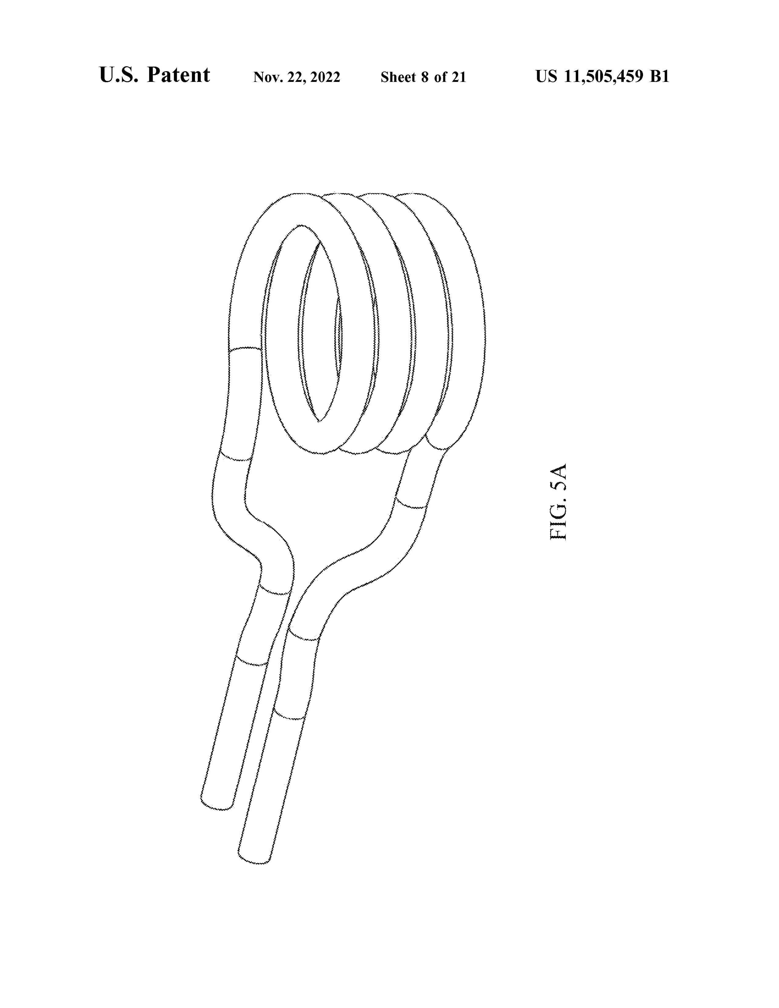
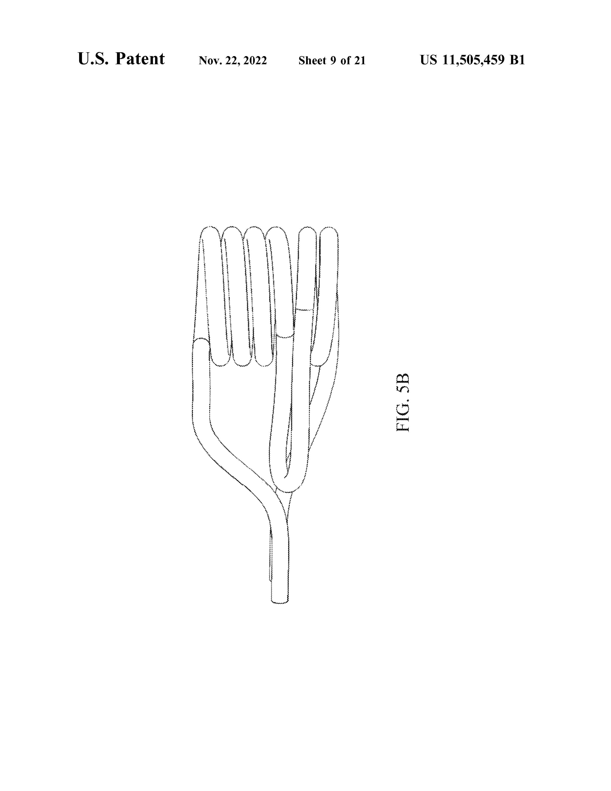
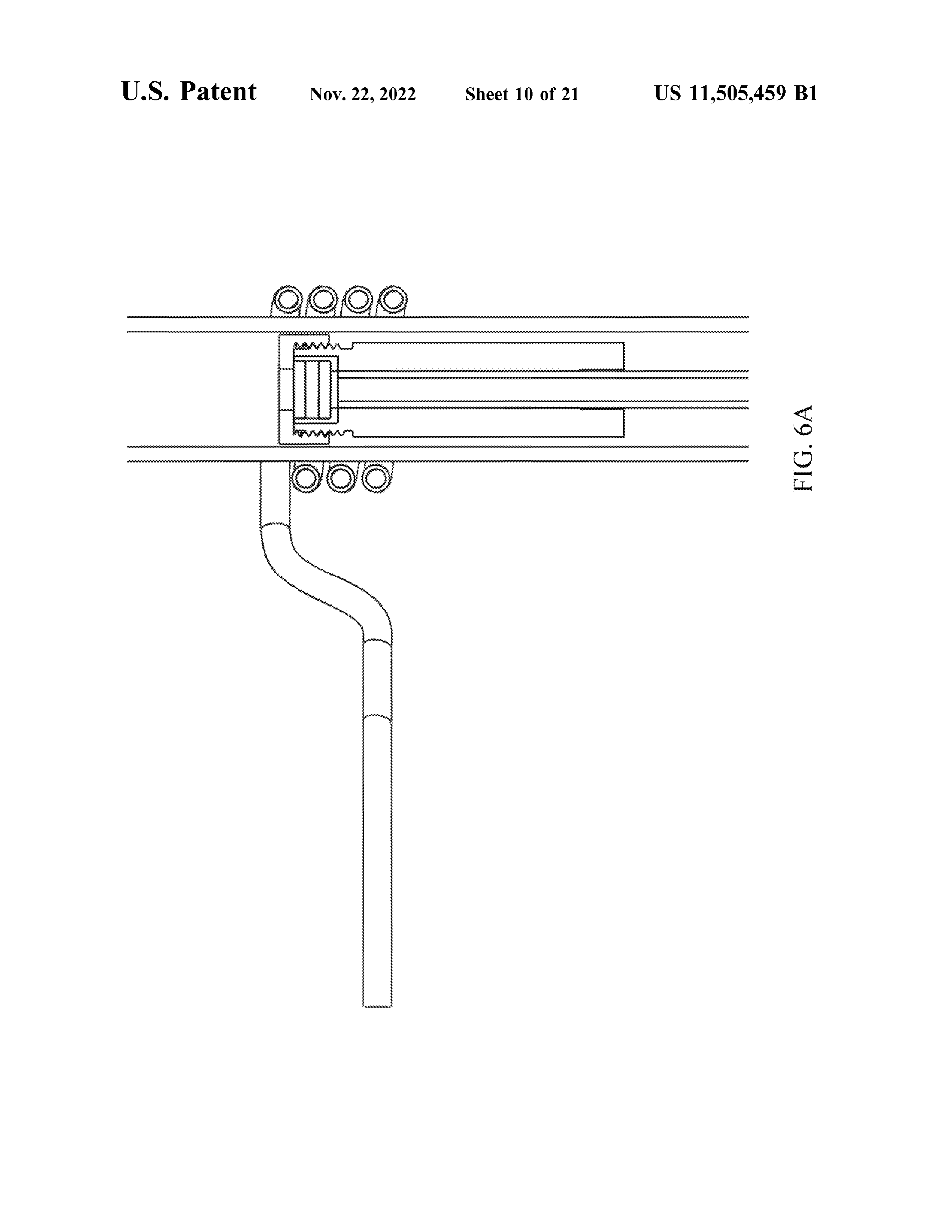
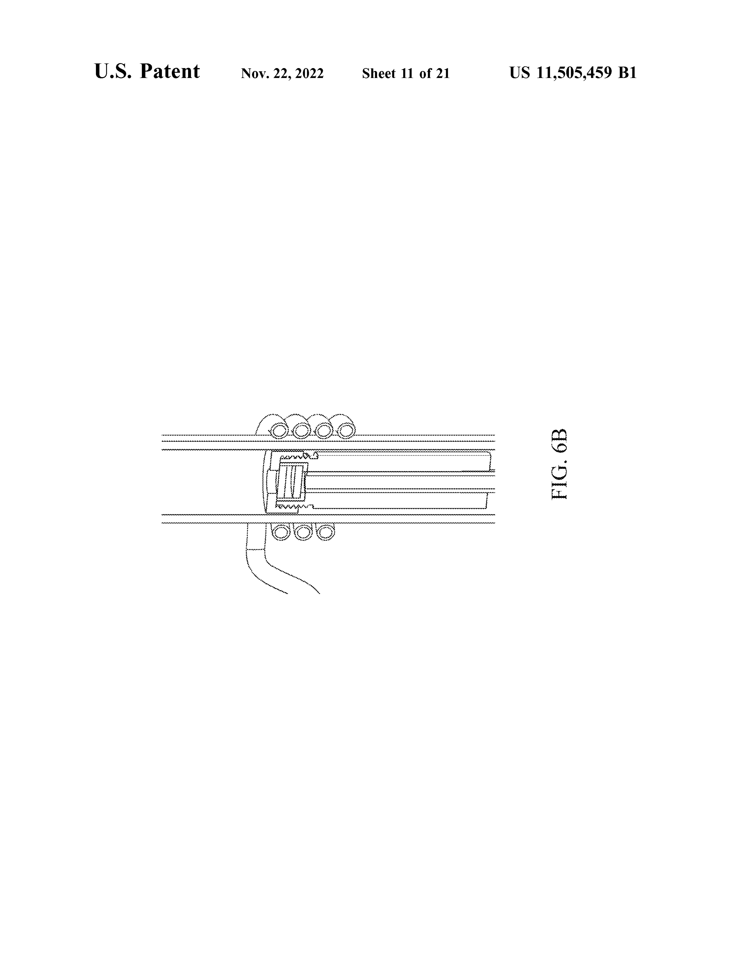
units, preferably the central processing unit ( CPU ) of FIG . 5A illustrates one conformation for a standard coil . the reactor assembly . Typically, a CPU independently FIG . 5B illustrates one conformation for a reverse field coil . controls powering each E/MEE pencil lamp and a FIGS . 6A and B are illustrations of two examples of two rotation position of each E/ MEE pencil lamp . composite reactor assemblies . FIG . 6A illustrates a Com As will be described in more detail below, the E/MEE 25 posite Reactor with a copper body, carbon graphite cup and housing can be typically closed and opaque, the internal gas a carbon graphite cap . FIG . 6B illustrates a Composite line can be transparent and external gas line in fluid con- Reactor with a carbon graphite body and cap and metal foil nection with the housing outlet and gas inlet can be opaque. boundary.
Typically, the internal gas line is between 50 cm and 5 FIGS . 7A - 71 illustrate various reactor assembly views meters or more and has aa diameter between 2 mm and 25 cm 30 according to the invention .
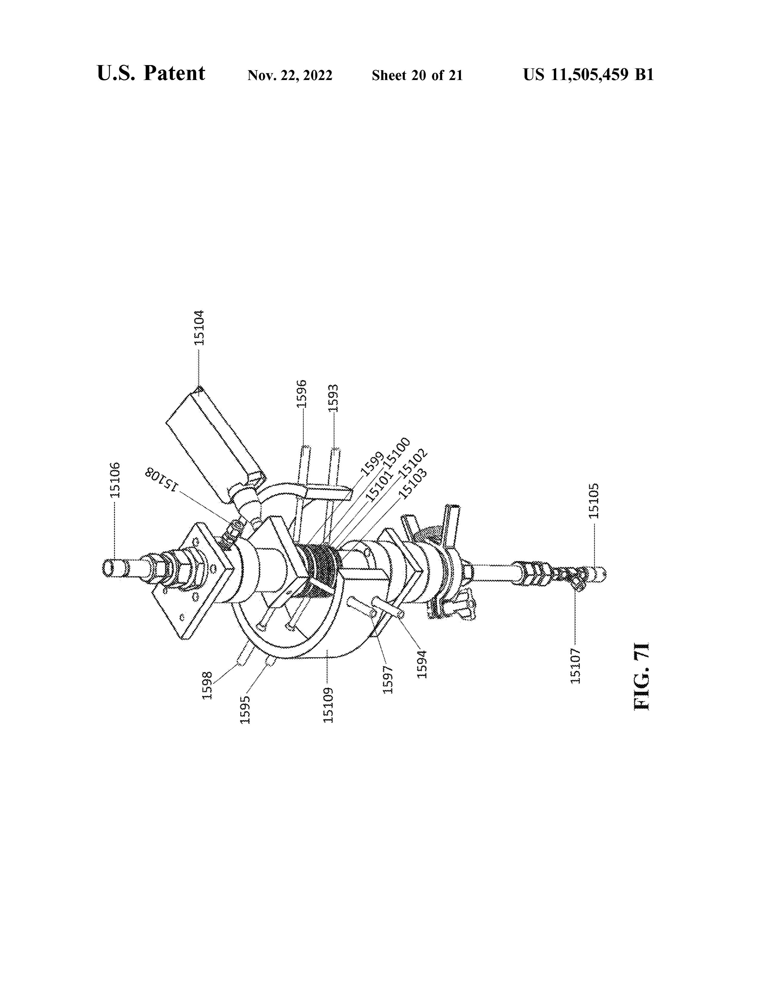
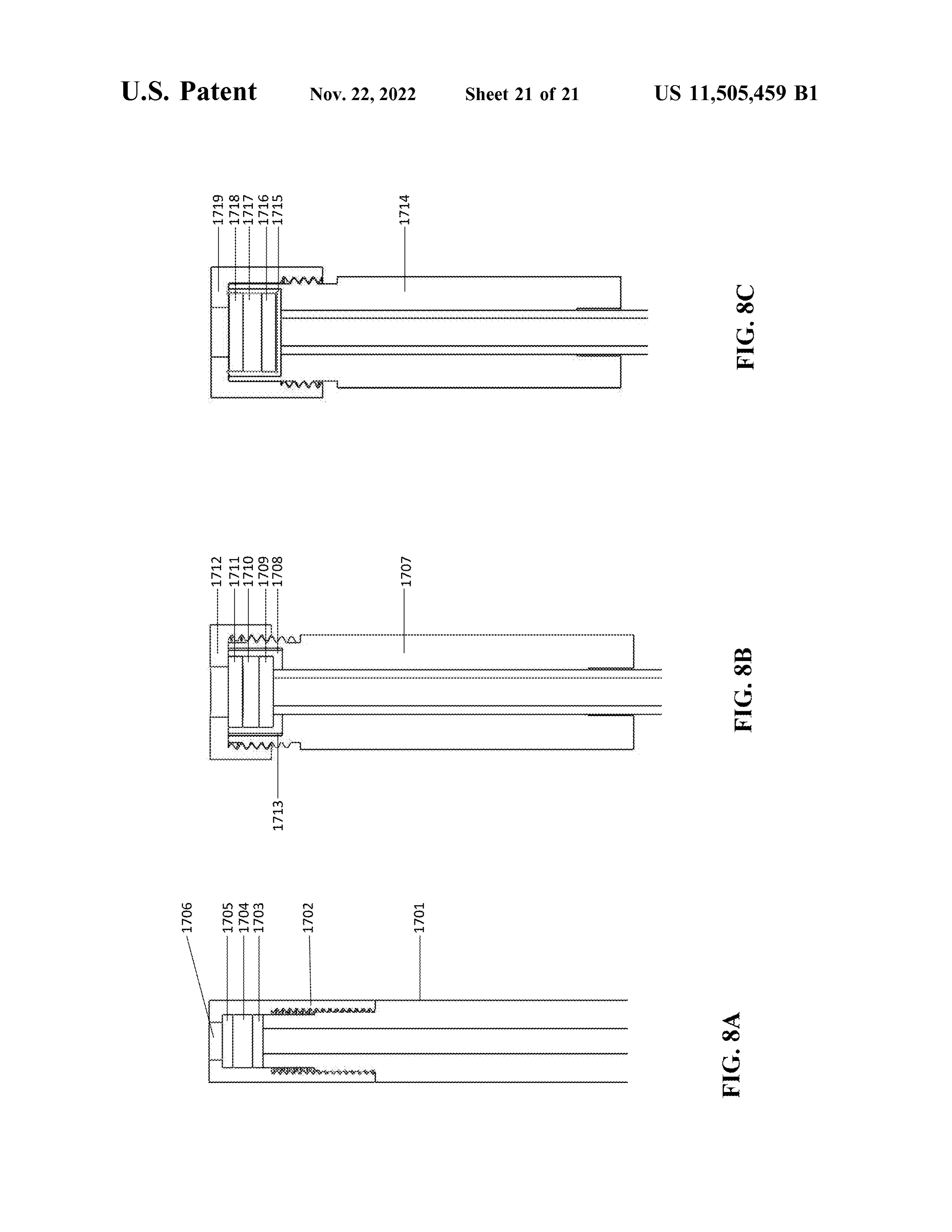
or more . FIGS . 8A - 8C are illustrations of reactor variations . As will be described in more detail below , the apparatus can have at least 5 E/MEE pencil lamps located along the DETAILED DESCRIPTION internal gas line . Each E/MEE pencil lamp can be indepen dently placed such that its longitudinal axis is (i ) parallel to 35 The invention relates to methods of instantiating hydro the internal gas line, (ii ) disposed radially in aa vertical plane gen in nanoporous carbon powders. The invention includes to the internal gas line , or (iii ) perpendicular to the plane methods comprising the steps of contacting a bed compris created along the longitudinal axis of the internal gas line or ing a nanoporous carbon powder with a first gas composi along the vertical axis of the internal gas line . Each E/MEE tion , and optionally an electromagnetically activated gas , pencil lamp can be independently affixed to one or more 40 while applying electromagnetic radiation to the nanoporous pivots that permit rotation between about 0 and 360 degrees carbon powder for a time sufficient to cause instantiation with respect to the x , y, and / or Zz axis wherein (i ) the x - axis within and /or from carbon nanopores . The process results in is defined as the axis parallel to the gas line and its vertical a product gas composition comprising hydrogen substan plane , ( ii ) the y - axis defining the axis perpendicular to the tially distinct from the first gas composition. The processes gas line and parallel to its horizontal plane, and ( iii ) the 45 of the invention have broad applicability in producing z - axis is defined as the axis perpendicular to the gas line and hydrogen , such as hydrogen on demand. parallel to its vertical plane. Nanoporous Carbon Powders As will be described in more detail below, at least one Nanoporous carbon powders or nanostructured porous E/MEE pencil lamp can be a neon lamp, at least one E/MEE carbons can be used in the processes and methods of the pencil lamp can be a krypton lamp, and at least one E/MEE 50 invention. Nanoporous carbon powders or nanostructured pencil lamp can be an argon lamp. It can be desirable to porous carbons are also referred to herein as “ starting match , or pair, one or more E/MEE pencil lamps with one material ” or “ charge material ” . The carbon powder prefer or more ( e.g. , a pair) of RA lamps. Accordingly, at least one ably provides a surface and porosity (e.g. , ultra -microporo pair of RA pencil lamps can be selected from the group sity ) that enhances metal deposition, including deposit, consisting of a neon lamp, a krypton lamp and an argon 55 instantiation and growth . Preferred carbon powders include lamp. activated carbon, engineered carbon , graphite, and gra As will be described in more detail below, the invention phene. For example, carbon materials that can be used also includes nanoporous carbon powder compositions and herein include graphene foams, fibers, nanorods, nanotubes , gas compositions produced in accordance with the claimed fullerenes, flakes, carbon black , acetylene black, mesophase methods and processes. 60 carbon particles, microbeads and, grains. The term “ pow der ” is intended to define discrete fine, particles or grains .
BRIEF DESCRIPTION OF THE DRAWINGS The powder can be dry and flowable or it can be humidified and caked , such as a cake that can be broken apart with
The patent or application file contains at least one drawing agitation . Although powders are preferred , the invention executed in color. Copies of this patent or patent application 65 contemplates substituting larger carbon materials, such as publication with color drawing ( s ) will be provided by the bricks and rods including larger porous carbon blocks and Office upon request and payment of the necessary fee . materials, for powders in the processes of the invention .
Page 25
The examples used herein typically describe highly puri- Preferred carbon materials ( e.g. , powders ) are characterized fied forms of carbon, such as > 99.995 % wt . pure carbon with a significant number, prevalence or concentration of (metals basis ) . Highly purified forms of carbon are exem- ultra -micropores having the same diameter, thereby provid plified for proof of principal, quality control and to ensure ing predictable electromagnetic harmonic resonances and / or that the results described herein are not the result of cross- 5 standing wave forms within the pores , cavities, and gaps . contamination or diffusion within the carbon source . How- The word “ diameter ” in this context is not intended to ever, it is contemplated that carbon materials of less purity require a spherical geometry of a pore but is intended to can also be used . Thus, the carbon powder can comprise at embrace a dimension ( s) or other characteristic distances least about 95 % wt . carbon , such as at least about 96 % , 97 % , between surfaces. Accordingly, preferred carbon materials 98 % or 99 % wt . carbon . In a preferred embodiment, the 10 (e.g. , powders) are characterized by a porosity (e.g. , nan carbon powder can be at least 99.9 % , 99.99 % or 99.999 % opores or ultramicropores) of the same diameter account for wt . carbon . In each instance, purity can be determined on at least about 10 % of the total porosity, such as at least about either an ash basis or on a metal basis . In another preferred 20% , at least about 30 % , at least about 40 % , at least about embodiment, the carbon powder is a blend of different 50% , at least about 60 % , at least about 70 % , at least about carbon types and forms. In one embodiment, the carbon bed 15 80% , or at least about 90% .
is comprised of a blend of different nano - engineered porous Measuring adsorption isotherm of a material can be useful carbon forms. Carbon powders can comprise dopants. to characterize the surface area, porosity, e.g. , external The carbon powder preferably comprises microparticles. porosity, of the carbon material. Carbon powders having a The volume median geometric particle size of preferred surface area between about 1 m²/ g and 3000 m²/ g are carbon powders can be between less than about 1 um and 5 20 particularly preferred. Carbon powders having an ultrami mm or more . Preferred carbon powders can be between cropore surface area of at least about 50 m²/ g, preferably at about 1 um and 500 um , such as between about 5 um and least about 300 m²/ g , at least about 400 m²/ g , at least about 200 um . Preferred carbon powders used in the exemplifica- 500 m´ /g or higher are particularly preferred. Activated or tion had median diameters between about 7 um and 13 um engineered carbons, and other quality carbon sources, can be and about 30 um and 150 um . 25 obtained with a surface area specification. Surface area can The dispersity of the carbon particle size can improve the be independently measured by BET surface adsorption quality of the products . It is convenient to use a carbon technique.
material that is homogeneous in size or monodisperse. Thus, Surface area correlation with metal deposition was a preferred carbon is characterized by a polydispersity index explored in a number of experiments. Classical pore surface of between about 0.5 and 1.5 , such as between about 0.6 and 30 area measurements , using Micromeritics BET surface area 1.4 , about 0.7 and 1.3 , about 0.8 and 1.2 , or between about analytical technique with nitrogen gas at 77K ( -196.15 C )
0.9 and 1.1 . The polydispersity index ( or PDI ) is the ratio of did not reveal a substantial correlation in the deposition of the mass mean diameter and number average diameter of a metal elements at 250 confidence or probability of particle population. Carbon materials characterized by a coincidence . However, a correlation with ultramicropores bimodal particle size can offer improved gas flow in the 35 ( pores having a dimension or diameter of less than 1 nm ) reactor. was observed . Without being bound by theory, instantiation The carbon powder is preferably porous. The pores , or is believed to be correlated to resonating cavity features of cavities , residing within the carbon particles can be mac- the ultra -micropore and ultramicropore network such as the ropores, micropores, nanopores and /or ultra - micropores . A distance between surfaces or walls . Features of the ultrami pore can include defects in electron distribution , compared 40 cropore, can be predicted from ultramicropore diameter as to graphene, often caused by changes in morphology due to measured by BET, augmented by density function theory holes , fissures or crevices, corners , edges , swelling , or (DFT ) models , for example. With the aid of machine learn changes in surface chemistry, such as the addition of chemi- ing , more precise relationships between ultramicropore size , cal moieties or surface groups , etc. For example , variation in distribution , turbostratic features, wall separation and diam the spaces that may arise between layers of carbon sheets , 45 eter and elemental metal nucleation can be established . fullerenes or nanotubes are contemplated . It is believed that Carbon materials and powders can be obtained from instantiation preferentially occurs at or within a pore or numerous commercial providers. MSP - 20X and MSC - 30 defect -containing pore and the nature of the surface char- are high surface area alkali activated carbon materials with acteristics can impact instantiation . For example, Micromer- nominal surface areas of 2,000-2,500 m²/ g and >3,000 m² /g itics enhanced pore distribution analysis ( e.g. , ISO 15901-3 ) 50 and median diameters of 7-13 um and 60-150 um respec can be used to characterize the carbon . It is preferred that the tively (Kansai Coke & Chemicals Co ) . Norit GSX is a carbon powder is nanoporous. A “ nanoporous carbon pow- steam -washed activated carbon obtained from Alfa Aesar . der ” is defined herein as a carbon powder characterized by The purified carbon forms used in the experimental section nanopores having a pore dimension ( e.g. , width or diameter) all exceed 99.998 wt % C (metals basis ) . of less than 100 nm . For example , IUPAC subdivides 55 Modifying the surface chemistry of the carbon can also be nanoporous materials as microporous (having pore diam- desirable . For example, improved performance was eters between 0.2 and 2 nm ), mesoporous materials ( having observed when conditioning the carbon with an acid or base . pore diameters between 2 and 50 nm ) and macroporous Contacting the carbon with a dilute acid solution selected materials (having pore diameters greater than 50 nm ). Ultra- from the group consisting of HCl , HF, HBr, HI , sulfuric acid , micropores are defined herein as having pore diameters of 60 phosphoric acid, carbonic acid, and nitric acid followed by less than about 1 nm . washing with water ( such as deionized water) can be ben Uniformity in pore size and / or geometry is also desirable . eficial. The acid is preferably in an amount less than about For example, ultramicropores in preferred carbon materials 30% , less than about 25 % , less than about 20% less than ( e.g. , powders ) account for at least about 10 % of the total about 15 % , less than about 10 % , or less than about 5 % , porosity, such as at least about 20 % , at least about 30 % , at 65 preferably less than or equal to 1 % vol . The preferred acid least about 40 % , at least about 50 % , at least about 60 % , at for an acid wash is an acid having a pKa of less than about least about 70 % , at least about 80 % , or at least about 90 % . 3 , such as less than about 2. After washing , it can be
Page 26
beneficial to subject the carbon to a blanket of a gas , such as respectively . MSC - 30 ( Kansai Coke and Chemicals ) was helium , hydrogen or mixtures thereof. Alternative gases acid washed and then hydrogenated to form MSC30 lots include carbon monoxide , carbon dioxide , nitrogen , argon , 1010 when washed with HCl and 1011 when washed with neon , krypton, helium , ammonia and hydrogen. The carbon HNO3 . MSC - 30 was exposed to an alkali ( C : KOH at a can also be exposed to a base , such as KOH before or after 5 molar ratio of 1 : 0.8 ) , activated at 700 C for 2 hours , HCl or an acid treatment. nitric acid washed and then hydrogenated to form MSC - 30 Controlling residual water content in the carbon which lots 1014 (HCl washed ) and 1015 ( HNO3 washed ), respec may include moisture can improve performance. For tively . MSP - 20X , MSC - 30 , Norit GSX and Alfa Aesar R example , the carbon material can be placed in an oven at a were subjected to purification by MWI , Inc. for MSP - 20X temperature of at least about 100° C. , preferably at least 10 Lots 2000 and 2004, MSC-30 Lots 2001 , 2006 and 2008 , about 125 ° C. , such as between 125 ° C. and 300 ° C. for at least 30 minutes such as about an hour. The oven can be at Norit GSX Lots 2005 and 2007 , and Alfa Aesar R Lot 2009 ambient or negative pressure , such as under a vacuum . respectively HCl washed
and hydrogenated to form MSP - 20X Lot 2002
Alternatively, the carbon material can be placed in an oven with high vacuum at a temperature of at least about 250° C., 15 washed and MSCwith-301 %Lot, 5 %2003 , respectively. Alfa Aesar R was
preferably at least about 350 ° C. , for at least one hour, such ( vol .) and then hydrogenated to for R Lot Graphite n % vol as at least 2 , 3 , 4 , 5 , or 6 hours. Alternatively, the carbon
material can be placed in an oven with high vacuum at a HCl , respectively . Purified MSP - 20X ( Lot 2006 ) was simi temperature of at least about 700 ° C. , preferably at least larly washed by HCl , nitric acid , HF or H2SO4. to form about 850 ° C. , for at least one hour, such as at least 2 , 3 , 4 , 20 MSP - 20X 1 % HCI , MSP - 20X 1 % HNO3 , MSP - 20X 0.4 % 5 , or 6 hours. Alternatively, the water or moisture can be HF, MSP - 20X 0.55 % H2SO4 ( Lot 1044 ) , respectively. Puri removed by vacuum or lyophilization without the applica- fied Norit GSX (Lot 2007 ) was similarly washed by nitric tion of substantial heat. Preferably, the water, or moisture, acid, HF or H2SO4 to form Norit GSX 1 % HNO3 (Lot 1045 ) , level of the carbon is less than about 35 % , 30 % , 25 % , 20 % , Norit -GSX 0.4 % HF, Norit- GSX 0.55 % H2SO4 , respec 15 % , 10 % , 5 % , such as less than about 2 % , by weight 25 tively . Purified MSC30 (Lot 2008 ) was similarly washed by carbon . In other embodiments, the carbon can be exposed to HCl and H2SO4 to form MSC30 1 % HCl , and MSC30 5 % a specific relative humidity (RH ) such as 0.5 % , 1 % , 2 % , 5 % , H2SO4 . Purified MSP20X (Lot 2006 ) , Norit GSX (Lot 2007 ) 12 % RH or 40% RH or 70% RH or 80% RH or 90% RH , and MSC30 (Lot 2008 ) were hydrogenated. Purified MSP for example, at 22 ° C. 20X , Norit GSX and MSC30 were washed with 1 % HC1 Pre - treatment of the carbon material can be selected from 30 using methanol as a wetting agent. APKI - S - 108 Lots 1021 one or more , including all , the steps of purification, humidi- 1024 were recycled . The Ref - X Blend is a 40% Alfa Aesar fication, activation, acidification , washing, hydrogenation , R : 60 % MSP - 20X ( lot 2006 ) 850 ° C. desorb then CO2 drying, chemistry modification ( organic and inorganic ), and exposure at 138 kPa ( 20 psi ) for 5 days . blending. For example, the carbon material can be reduced , It is preferred to degas the nanoporous carbon powder protonated or oxidized . The order of the steps can be as 35 prior to initiating the process . For example, the nanoporous described, or two or more steps can be conducted in a carbon powder can be degassed by subjecting the powder to different order. a vacuum . A range of vacuums can be used , with or without For example, MSP - 20X was exposed to an alkali ( C : KOH elevated temperatures . It has been found that applying a at a molar ratio of 1 : 0.8 ) , activated at 700 ° C. for 2 hours , vacuum of about 10-2 torr to 10-6 torr was sufficient. The washed with acid and then hydrogenated to form MSP - 20X 40 powder can be degassed prior to charging the powder into Lots 1000 when washed with HC1 and 105 when washed the reactor chamber. Preferably the powder can be degassed with HNO3 . MSP - 20X was washed with acid and then after the powder is charged into the reactor chamber. In the hydrogenated to form MSP - 20X Lots 1012 when washed examples below, which are non - limiting, the carbon powder with HCl and 1013 when washed with HNO3 . Activated is charged into the reactor chamber, placed into the reactor carbon powder developed for the storage of hydrogen was 45 assembly and the entire reactor assembly is subjected to a HCl acid washed, then subjected to HNO3 washing and degassing step by maintaining the reactor assembly under hydrogenation to form APKI lots 1001 and 1002 , as sub- vacuum . The degassing step can be performed at ambient stantially described in Yuan , J. Phys. Chem . temperature or an elevated temperature. For example, good B20081124614345-14357 ]. Poly ( ether ether ketone) results were achieved at a temperature of 400 C. Other ( PEEK , Victrex 450P ) and poly (ether imide) ( PEI , Ultem® 50 temperatures can be at least 50 C , such as at least 100 C , at 1000 ) was supplied by thermally oxidized in static air at least 150 C , at least 200 C , or at least 300 C. The degassing 320 ° C. for 15 h , and carbonized at the temperature range of step can be maintained for at least 30 minutes, such as at 550-1100 ° C. in nitrogen atmosphere, at the carbon yield of least 45 minutes, at least 60 minutes, at least 4 hours , at least 50-60 wt % . These carbons were then activated by the 6 hours, at least 12 hours, or at least 24 hours . Degassing the following procedures: ( 1 ) grind the carbonized polymer with 55 carbon powder ensures that contaminant elements have been KOH at KOH / carbon ~ 1 / 1-1 / 6 ( w / w ), in the presence of removed from the system .
alcohol , to form a fine paste ; (2 ) heat the paste to 600-850 ° The carbon can be recycled or reused . In recycling the C. in nitrogen atmosphere for 2 h ; ( 3 ) wash and rinse with carbon, the carbon can optionally be subjected to an acid DI water and dry in vacuum oven . PEEK / PEI ( 50/50 wt ) wash and / or water removal one or more times . In this blend was kindly supplied by PoroGen , Inc. Likewise, the 60 embodiment, the carbon can be reused one or more times , acid washing sequence of Lots 1001 and 1002 was reversed such as 2 , 3 , 4 , 5 , 10 , 15 , 20 , or about 25 or more times . The to form APKI lots 1003 and 1004. Universal grade, natural carbon can also be replenished in whole or in part. It has graphite, ~ 200 mesh was purchased from Alfa Aesar, prod- been discovered that recycling or reusing the carbon can uct number 40799. Graphite lots R and Z were HCl washed enhance metal nanostructure yields and adjust nucleation and hydrogenated to form R lot 1006 and Z lot 1008 , 65 characteristics enabling change in element selectivity and respectively. Alfa Aesar graphite R and Z were nitric acid resultant distributions . Thus, an aspect of the invention is to washed and hydrogenated to form R lot 1007 and Z lot 1009 , practice the method with recycled nanoporous carbon pow
Page 27
der, e.g., a nanoporous carbon powder that has been previ- internal gas line and / or at least one pencil lamp posi ously subjected to a method of the invention one or more tioned to the side of the internal gas line ; times . an optional short wave lamp and / or a long wave lamp; and Nanoporous Carbon Compositions an optional coil wrapped around the internal gas line , The nanoporous carbon compositions produced by the 5 operably connected to a frequency generator; processes described herein possess several surprising and wherein each lamp is independently rotatably mounted , unique qualities. The nanoporosity of the carbon powder is located along the length of the internal gas line, and generally retained during processing and can be confirmed , powered by the power supply ; and for example, visually with a scanning electron microscope wherein the central processing unit independently con or modeled by BET analysis . Visual inspection of the 10 trols powering the frequency generator, if present, and powder can identify the presence of elemental nanostruc each lamp and the rotation position of each lamp. tures residing within and surrounding the nanopores . The Feed gases can preferably be research grade or high purity nanostructures are typically elemental metals. Visual inspec- gases , for example, as delivered via one or more gas tion of the powder can also identify the presence of elemen- supplies, such as a compressed gas cylinder. Examples of tal macrostructures residing within and surrounding the 15 gases that can be used include, for example, air, oxygen , nanopores. The macrostructures are typically elemental met- nitrogen, helium , neon , argon , krypton, xenon , ammonium , als and often contain interstitial and / or internal carbon , as carbon monoxide, carbon dioxide and mixtures thereof. generally described by Inventor Nagel in U.S. Pat. No. Preferred gases include nitrogen , helium , argon , carbon 10,889,892 , which is incorporated herein by reference, in its monoxide, carbon dioxide and mixtures thereof. Nitrogen, entirety. Methods for instantiating gases are described in 20 air and helium are preferred . In the examples below, a highly U.S. Ser. No. 63 / 241,697 by Inventor Nagel , which is purified nitrogen gas was used . The use of highly purified incorporated herein by reference in its entirety . nitrogen gas facilitated product gas analysis. The feed gas Typically, the porosity of the nanoporous carbon compo- can be added continuously or discontinuously, throughout sitions will be at least about 70 % of the porosity attributed the process.
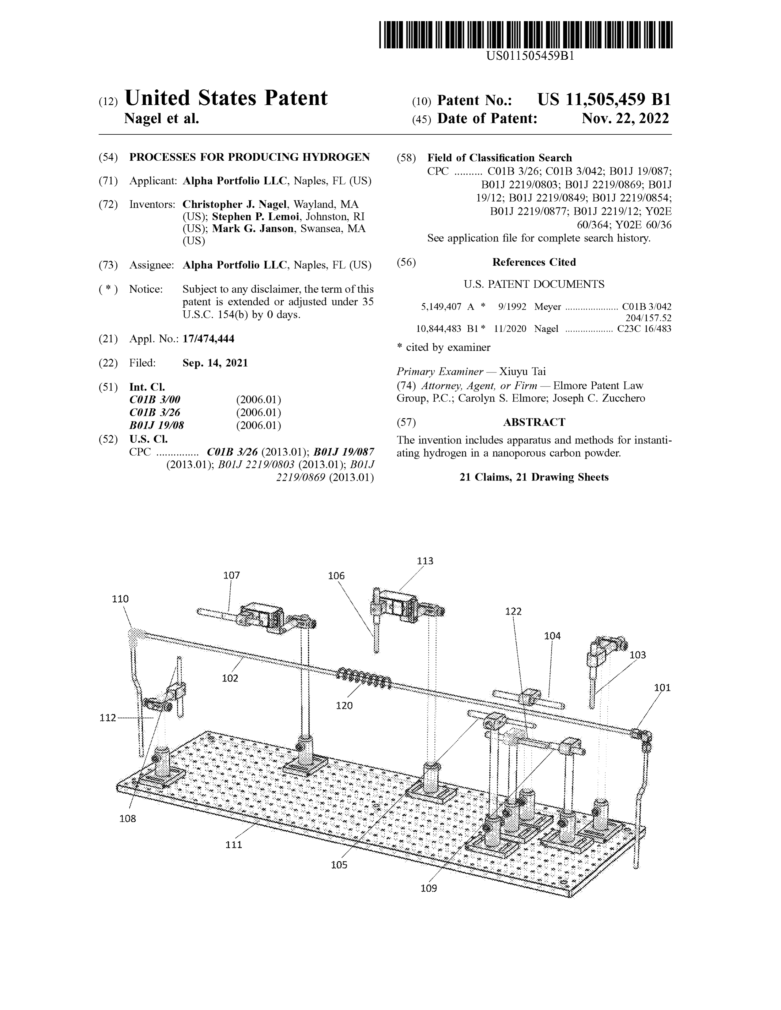
to ultramicropores of the nanoporous carbon powder start- 25 One or more gases (e.g. , 2 , 3 , 4 , 5 , or more gases ) can ing , or charge, material and having a total void volume that optionally pass through a gas manifold comprising mass is about 40% or more of the bulk material volume . The flow meters to produce a first gas composition , also called pores, or cavities , residing within the carbon particles can be the reactor feed gas . The reactor feed gas may then either macropores, micropores, nanopores and /or ultra -micropo- by - pass an electromagnetic (EM) embedding enclosure res . A pore can include defects in electron distribution , 30 (E/ MEE ) or pass through one or more E/MEEs . The E/MEE compared to graphene, often caused by changes in morphol- exposes the reactor feed gas to various electromagnetic field ogy due to holes , fissures or crevices, edges , corners, swell- (EMF ) sources . Flow rates, compositions, and residence ing , dative bonds, or other changes in surface chemistry, times can be controlled . The rate of flow of the reactor feed such as the addition of chemical moieties or surface groups, gas can be between 0.01 standard liters per minute ( SLPM ) etc. For example, the spaces that may arise between layers 35 and 10 SLPM , or 100 SLPM or more . A constant flow of gas of carbon sheets, fullerenes, nanotubes, or intercalated car- can maintain a purged environment within the reactor. The bon are contemplated. It is believed that instantiation pref- schematics shown in FIG . 1 depicts a flow path for the gases erentially occurs at or within a pore and the nature of the through a sample E/MEE . The sample E/MEE comprises a surface characteristics can impact the deposit. For example, series of lights and coils that can optionally expose the Micromeritics enhanced pore distribution analysis ( e.g. , ISO 40 reactor feed gas to EM radiation . EMF sources within the 15901-3 ) can be used to characterize the carbon . It is E/MEE can be energized simultaneously or in sequence or preferred that the carbon powder is nanoporous . It has now a combination thereof.
been surprisingly found that hydrogen and other light mate- FIG . 1 is an illustration of an E/MEE of the invention . Gas rials can be instantiated and collected in the gas stream . enters the E /MEE via the inlet 101 , or entrance , in line 102 Methods and Apparatus 45 and exits at the outlet, or exit , 110. The inlet 101 and outlet Conceptually, the apparatus for baseline experimentation 110 may optionally have valves .
can be broken into two primary areas : Gas Processing and Line 102 can be made of a transparent or translucent Reactor Assembly. material ( glass is preferred ) and / or an opaque or non Gas Processing: translucent material, such as stainless steel or non -translu The gas processing section controls gas composition and 50 cent plastic ( such as TYGON® manufactured by Saint flow rate, with the optional embedding of electromagnetic Globain Performance Plastics ) or a combination thereof. ( e.g. , light) information or electromagnetic gas pre -treat- Using an opaque material can reduce or eliminate electro ment to the reactor. The invention includes an electromag- magnetic exposure to the gas as the gas resides within the netic embedding enclosure (E/ MEE or EMEE ) , or apparatus, line . The length of line 102 can be between 50 cm and 5 for processing a gas ( feed gas or first gas composition, used 55 meters or longer. The inner diameter of line 102 can be interchangeably herein ) comprising or consisting of: between 2 mm and 25 cm or more . Line 102 can be a central processing unit and power supply ; supported on and / or enclosed within a housing or substrate one or more gas supplies ; 111 , such as one or more plates , with one or more supports a housing having a housing inlet and housing outlet ; 112. For example, substrate 111 can be configured as a plane an upstream gas line that is in fluid connection with each 60 or floor, pipe or box . Where the substrate is aa box , the box gas supply and the housing inlet; can be characterized by a floor, a ceiling and side walls . The an internal gas line in fluid connection with the housing box can be closed to and / or insulated from ambient EM inlet and housing outlet; radiation , such as ambient light.
a downstream gas line in fluid connection with the hous- One or more lamps ( such as 2 , 3 , 4 , 5 , 6 , 7 , 8 , 9 , 10 lamps
ing outlet ; 65 or more) can be configured within the E/MEE . Lamps at least one pencil lamp positioned below the internal gas (numbered individually ) are preferably pencil lamps char line, at least one pencil lamp positioned above the acterized by an elongated tube with a longitudinal axis . The
Page 28
pencil lamps can independently be placed such that its vertical plane along line 102 , as illustrated by lamps 122 , longitudinal axis is ( i ) parallel to the line 102 , ( ii ) disposed 104 , and 105. Two lamps are in the same vertical plane if
radially in a vertical plane to the line 102 , or (iii ) perpen- they ( as defined by the tip or base of the lamp) are the same dicular to the plane created along the longitudinal axis of the distance from the inlet 101. Preferably, lamp 105 can be line 102 or along the vertical axis of the line 102 . 5 placed in a plurality of (e.g. , 2 , 3 , 4 , 5 or more ) vertical Each lamp can , independently, be fixed in its orientation planes along the length of line 102 within the E /MEE . by a support 112. Each lamp can, independently, be affixed Further, one or more lamps can be placed in the same to a pivot 113 to permit rotation from a first position . For horizontal plane above , below or through line 102 , as shown example , the lamps can be rotated between about 0 and 360 with lamps 104 and 105. Two lamps are in the same degrees , such as about 45 , 90 , 135 , 180 , 225 or 270 degrees, 10 horizontal plane if they ( as defined by the tip or base of the preferably about 90 degrees relative to a first position . The lamp) are the same distance from the center of line 102 . rotation can be with respect to the x , y , and / or zZ axis wherein Preferably, lamps can be placed in a plurality of ( e.g. , 2 , 3 , ( i ) the x - axis is defined as the axis parallel to the gas line and 4 , 5 or more ) horizontal planes along the length of line 102 its vertical plane, (ii ) the y - axis defining the axis perpen- within the E/MEE , as generally illustrated . dicular to the gas line and parallel to its horizontal plane, and 15 It is understood that “ pencil lamps ," as used herein , are ( iii ) the z - axis is defined as the axis perpendicular to the gas lamps filled with gases or vapor that emit specific, calibrated line and parallel to its vertical plane. wavelengths upon excitation of the vapor. For example , Referring to the specific pencil lamps within an E/MEE , pencil lamps include argon , neon , xenon , and mercury line 102 is configured along the E/MEE with gas flowing lamps. For example, one or a plurality of lamps can be from the inlet 101 and exiting at the outlet 110. Lamp 103 , 20 selected from argon , neon , xenon or mercury or a combi a neon lamp, is first and is shown above line 102 oriented to nation thereof. Preferably, at least one lamp from each of be along the z - axis and perpendicular to line 102 , with the argon, neon , xenon and mercury are selected . Wavelengths tip of the lamp pointed towards line 102. Lamp 109 , a between 150 nm and 1000 nm can be selected . One example krypton lamp, is shown below line 102 oriented to be of a pencil lamp is a lamp characterized by an elongated tube parallel to the x -axis, with the tip pointing towards the outlet 25 having a tip and a base .
110. Lamps 104 and 105 , a long wave and short wave lamp, Long wave and / or short wave ultraviolet lamps can also respectively, are shown parallel to line 102 oriented to be be used . Pencil lamps used in the E/ MEE were purchased along the x - axis with the tips pointing towards the inlet . from VWRTM under the name UVP Pen_Ray® rare gas Lamp 122 , an argon lamp, is shown to be below line 102 lamps, or Analytik Jena in the case of the UV short wave oriented to be parallel to the x -axis , with the tip pointing 30 lamps.
towards the inlet 101 at approximately the same distance A power supply is operably connected to independently to from the inlet as lamps 104 and 105. Lamp 106 , a neon lamp, each lamp, E /MEE coil , and frequency generator. The power is downstream at about the midpoint of the E/MEE , is above supply can be AC and /or DC .
line 102 with the tip pointing down . Lamp 107 , a xenon The E/MEE can be open or enclosed . Where the E/MEE lamp, is shown downstream of lamp 106 above line 102 , 35 is enclosed, the enclosure is typically opaque and protects parallel to the x axis of line 102 and points toward the outlet the gas from ambient light. The enclosure can be made of a 110. Lamp 108 , an argon lamp, is below line 102 and the tip plastic or resin or metal . It can be rectangular or cylindrical.
is pointing toward line 102 along the z - axis . Optional coil Preferably, the enclosure is characterized by a floor support . 120 is wrapped around line 102. Each of these lamps can be In baseline experimentation the feed gas can by -pass the independently rotated , for example, 90 degrees along any 40 E/MEE section and are fed directly to the reactor assembly. axis . Each lamp is connected to a power supply or power The energy levels and frequencies provided by the EM source to turn on or off the power. Each lamp can be sources can vary .
independently rotated 1 , 2 , 3 , 4 or more times during the FIG . 4A provides a second illustration of an E/MEE of the process. For convenience , each lamp is held by a pivot that invention . Gas enters the E/MEE at inlet 401 and exits at can be controlled by a central processing unit , such as a 45 outlet 409 along line 410. Pencil lamp 402 and Pencil lamp computer programmed to rotate the pivot and provide power 403 are shown parallel to and above line 410 along the to each lamp. For the ease of describing the experimental vertical plane through line 410 axis . Pencil lamps 404 and procedures, each orientation of each lamp is called " position 405 are parallel to and below line 410 in the same horizontal n ” wherein n is 0 , 1 , 2 , 3 , 4 , or more . As the procedure is plane equidistant from the vertical plane through line 410 . conducted , each lamp can be powered for specific periods of 50 Pencil lamp 406 is shown above and perpendicular to line time at specific amperage ( s) and positioned or repositioned . 410 , positioned along the z axis . An optional coil 407 is a In the exemplification described below , the initial bulb conductive coil wrapped around line 410. Pencil lamp 408 position for each lamp is described with a degree. A zero is shown below and perpendicular to line 410 along the y degree ( 0 ° ) reference point is taken as the 12 o'clock axis . Substrate 411 provides a base for supports 412. Pivots position on the glass pipe when looking down the gas pipe 55 413 control the position of each pencil lamp and permit in the direction of intended gas flow ( e.g. , when looking at rotation along axis x , y and z . An optional x -ray source 429 the E/ MEE exit) . The length of the glass pipe or line is taken is also shown directed towards the coil 407 . as the optical length ( e.g. , in this instance 39 inches ). For The coil 407 is preferably made of conducting material example, 6 inches from the end is defined as 6 inches from and is connected to a power supply and, optionally, a the optical end of pipe . 60 frequency generator. The coil can comprise copper, alumi The lamps can be placed above , below, or to the side ( for num , platinum , silver, rhodium , palladium or other metals or example, level with the longitudinal axis or a plane parallel alloys ( including braidings, platings and coatings ) and can to (above or below ) the longitudinal axis ), for example , of optionally be covered with an insulating coating, such as line 102. The lamps can be independently placed between 5 glyptal . It can be advantageous to use a braid of 1 , 2 , 3 or 9
and 100 cm from the center of the line 102 in the vertical 65 more metal wires . The coil can be manufactured from wire plane , as measured from the tip of the lamp to the center of typically used in an induction coil and can vary in size and line 102. One or more lamps can be placed in the same the number of turns . For example, the coil can comprise, 3 ,
Page 29
4 , 5 , 6 , 7 , 8 , 9 , 10 or more turns. The inner diameter of the The invention also includes a reactor assembly compris coil can be between 2 cm and 6 cm or more and preferably ing :
snugly fits the line 410. The wire used can have a diameter A gas inlet and one or more gas outlets; of between 5 mm and 2 cm . A reactor chamber, preferably containing a nanoporous An X - ray source 429 can included in the E/MEE . For 5 carbon material;
example, the x - ray source can be directed at line 410 along A first porous frit defining a floor of the reactor chamber, the line between the inlet 401 and outlet 409. For example, A second porous frit defining the ceiling of the reactor it can be advantageous to direct the x - ray source at coil 407 , chamber ; wherein each porous frit has a porosity that is where present. sufficient to allow a gas to permeate into the reactor Reactor Assembly ( RA ): 10 chamber and contain a nanoporous carbon material;
The invention further relates to a reactor assembly com- A reactor head space disposed above the reactor chamber ; prising: An induction coil surrounding the reactor chamber and / or A gas inlet and one or more gas outlets; reactor head space operably connected to a power A reactor chamber, preferably containing a nanoporous 15 supply ;
carbon material or powder ; A computer processing unit configured to control the A first porous frit defining a floor of the reactor chamber, power supply. The reactor chamber can optionally A second porous frit defining the ceiling of the reactor contain a cap and /or cup to contain the carbon material. chamber; wherein each porous frit has a porosity that is As shown in FIGS . 2A and 2B , the reactor assembly sufficient to allow a gas to permeate into the reactor 20 comprises a reactor body 202 and starting, or charge, mate chamber and contain a nanoporous carbon material; rial 204 ( which is generally a nanoporous carbon powder) An optional reactor cup defining side walls of the reactor and is located downstream of the gas sources 221 and chamber; E/MEE 222 , as shown in FIG . 2A . As described above, it is An optional reactor cap positioned above the second possible for reactor feed gas to bypass the E/ MEE . The porous frit; 25 reactor body 202 can be a packed bed tubular micro - reactor A reactor body disposed below the first porous frit; surrounded by one or more conducting coils 208 , as illus A reactor head space disposed above the reactor cap ; trated in FIG . 2B , a cross section of the reactor assembly. An optional foil disposed between the reactor chamber The conducting coil 208 can be manufactured from elec and reactor cup ;
trically conducting material, such as copper, aluminum , 30 platinum , silver, rhodium , palladium or other metals or
One or more coils surrounding the reactor body and / or the alloys ( including braidings, platings and coatings ) and can reactor chamber operably connected to a power supply optionally be covered with an insulating coating, such as and /or frequency generator; glyptal . The coil can be manufactured from wire typically An optional x - ray source configured to expose the reactor used in an induction coil and can vary in size and the number head space to X - rays ; 35 of turns. For example, the coil can comprise 3 , 4 , 5 , 6 , 7 , 8 , 2
One or more optional lasers configured to direct aa laser 9 , 10 or more turns. The inner diameter of the coil can be towards aa frit and /or through the reactor chamber ; between 2 cm and 6 cm or more and preferably snugly fits A computer processing unit configured to control the the reactor body containment 207. The wire used can have power supply, frequency generator, lamps , lasers and 40 a diameter of between 5 mm and 2 cm .
X - ray source , when present. Each conducting coil 208 ( or coil ) can generate inductive The invention also includes a reactor assembly compris heat and, optionally, a magnetic field . Standard induction ing : coils or reverse field induction coils ( coils that have aa lower A gas inlet and one or more gas outlets ; and upper sections connected through an extended arm that allows the sections to be wound in opposite directions ,
A reactor chamber, preferably containing a nanoporous 45 thereby producing opposing magnetic fields) are preferred. carbon material; The coil 208 can be water - cooled via a heat exchanger. The A first porous frit defining a floor of the reactor chamber, coil can be connected to a power flange 210 , which can be A second porous frit defining the ceiling of the reactor water cooled as well and in turn can connect to a power chamber ; wherein each porous frit has a porosity that is supply, such as an Ambrell 10 kW 150-400 kHz power sufficient to allow a gas to permeate into the reactor 50 supply. In baseline experimentation aa standard coil was used chamber and contain a nanoporous carbon material; with simple copper windings. The windings can form a coil A reactor head space disposed above the reactor cap ; such that the connection to the power supply is at opposite ends 2 , 3 , 4 , 5 or more RA coils surrounding the reactor connection of the coil FIG . 5A or the coil can return such that the chamber and / or reactor head space operably connected to the power supply are adjacent, as shown in to an RA frequency generator and power supply ; 55 FIG . 5B .
2 , 3 , 4 , 5 or more pairs of lamps wherein the pairs of or The more reactor assembly can optionally further comprise one coils 208 , preferably surrounding the reactor body lamps are disposed circumferentially around the RA and its containment coils and define a space between the pairs of lamps and bly can comprise 1 , system
. For example, the reactor assem
the RA coils ; 60 also called RA coils . As shown in FIG . 2B , one or more An optional x - ray source configured to expose the reactor electromagnetic (E/M) coils can be used to provide magnetic chamber to X -rays; fields. Preferably, 1 , 2 , 3 , 4 , or 5 or more E/M coils can be One or more optional lasers configured to direct a laser used , more preferably 3 , 4 , or 5 E/ M coils . FIG . 3 shows through the reactor chamber, and groupings of three coils , for example, which can generally A computer processing unit configured to control the 65 be numbered 1 , 2 , or 3 , from top to bottom . A grouping of power supply, frequency generator and the optional coils , as shown in FIG . 3A - 3E , can be called a boundary. X -ray source and lasers. Where a plurality of groupings is used , the number of coils
Page 30
used is independently selected . Further, the groupings can be desirable to add additional RA coils , also aligned with a equidistantly spaced along or irregularly spaced. second or additional reactor chambers or nanoporous carbon Coils can be manufactured from electrically conducting beds . Additional RA coils can be added to align with materials, such as copper, platinum , silver, rhodium , palla- additional frits when present.
dium and , wire braids or coated wires of two or more 5 The RA coils can typically be supported in a support or materials. Each coil in a grouping may be made of the same stator to maintain a fixed distance between each coil . The material or different. For example, a grouping can be made support, when present, can be transparent. In one embodi such that each coil is made of a different material. For ment, the RA coils can be configured in a cartridge that can example , a braiding of copper wire and silver wire can be be removed or moved .
used . Silver plated copper wire can be used . A first RA coil 10 The RA coils can , additionally or alternatively, be aligned can be made of a copper winding . A second RA coil can be with the reactor headspace . The reactor headspace can a copper / silver braid . A third RA coil can be a platinum wire typically be a volume above the second, or top , frit. It is winding. An RA coil can be configured to create a magnetic understood that where the reactor assembly is positioned field and wherein each power supply independently provides horizontally ( or at some other angle than vertical), the AC and / or DC current. Any one or all RA coils can be 15 geometry of the spaces is maintained, albeit rotated . The optionally lacquered . reactor headspace can typically be an enclosed volume . For The coils are preferably circular in geometry. However, example , the reactor assembly can be inserted into aa closed other geometries, such as rounded shapes, ellipses and ended transparent ( e.g. , glass ) tube, vial or bottle. The ovoids can be used . The wire diameter can be between about reactor assembly can be movably engaged with the RA coils 0.05 mm (>about 40 gauge) and about 15 mm ( about 0000 20 (or boundary ), thereby permitting each RA coil to align to a gauge ) or more . For example, the wire diameter can be different element within the reactor assembly . For example, .
between about 0.08 mm ( about 40 gauge ) and about 0.8 mm the first RA coil can be realigned with the reactor chamber. ( about 20 gauge ) wire . Excellent results have been obtained Reactor body 202 can also be a packed, moving or using 0.13 mm (36 gauge) wire . Coils can be wire windings fluidized bed or other configuration characterized by one or ( e.g. , the wire can be wound in 1 , 2 , 3 , 4 , 5 , 6 , 7 , 8 , 9 , 20 , 25 more chambers that receive the charge material 204 and or more turns or can be a single turn . When the coil is made facilitates transfer of a reactor feed gas through the charge with a single winding, the diameter or width of the wire can material 204 and can transfer thermal and / or electromag preferably be 10 mm or more in diameter. In this context, a netic energy to the charge material 204. The reactor body “ wire " can also be considered a band where the width of the 202 is generally contained within a housing, e.g. , closed end material is greater than the depth . FIG . 3 provides illustra- 30 tube, 207 and frits 203 , which function to contain the charge tions or views of various coils and groupings of coils . A wire material 204. It can be advantageous to use a reactor within coil can be made of a single wire, a wire alloy or two or more a translucent or transparent housing, such as quartz or other wires . For example , two wires comprising different metals materials characterized by a high melting point. The volume can be wound or braided together. of the reactor bed can be fixed or adjustable. For example, The inner diameter ( or dimension ( s ) where the coil is not 35 the reactor bed can contain about 1 gram , or less of starting a circle) of each coil can be the same or different and can be material, between about 1 g to 1 kg of starting material or between 2 and 200 cm . more . Where the reactor assembly comprises two or more Coils 208 can independently be connected to one or more reactor chambers, the reactor chambers are preferably power supplies , such as an AC or DC power supply or directly or indirectly stacked, preferably having a common combination thereof. For example, an AC current can be 40 central axis and can be separated by one or two frits . supplied to alternating ( 1,3 , and 5 , for example ) or adjacent The reactor body 202 can be made of a thermally con coils ( 1 , 2 and / or 4 , 5 , for example ) while DC current is ductive material, such as graphite , copper, aluminum , nickel , supplied to the remaining coils . Current can be provided molybdenum , platinum , iridium , cobalt , or niobium , or ( independently ) in a frequency, such as in a patterned non - thermally conducting material, such as quartz, plastic frequency, e.g. , triangle, square or sine pattern or combina- 45 (e.g. , acrylic ), or combinations thereof. An optional cup 206 tion thereof. The frequency supplied to each coil can be the capped with cap 205 can be advantageous. The cup and cap same or different and between 0 to 50 MHz or higher. While material can be independently selected . For example, a the coils 208 can generate and transfer thermal energy, or graphite cup can be combined with a graphite cap , which is heat , to the reactor feed gas they are predominantly used to the selection for the examples below . A copper cup can be create a magnetic field . 50 combined with a graphite cap . A graphite cup can be The power supply can be an AC and / or DC power supply combined with a copper cap . A copper cup can be combined or combination thereof. Current can be provided (indepen- with a copper cap and so on .
dently ) in a frequency, such as in a patterned frequency, e.g. , The reactor assembly can also receive the gas line through triangle, square or sine pattern or combination thereof. The the entrance, or inlet , 201 and to provide an exhaust through frequency supplied to each coil can be the same or different 55 an exit , or outlet, 209 , optionally controlled by valves . A and between 0 to 50 MHz or higher, such as between 1 Hz head space defined by a closed end tube 207 can be to 50 Mhz . configured above the reactor body. The reactor body is As described above , the RA coils typically surround the preferably made of graphite, copper, or other inorganic rigid reactor chamber and / or reactor head space . For example, a material. The gas line is preferably made of an inert tubing, first RA coil can be aligned with the first ( or bottom ) frit. A 60 such as glass , acrylic, polyurethane, plexiglass, silicone , second RA coil can be aligned with the reactor chamber or stainless steel , and the like can also be used . Tubing can , nanoporous carbon bed . A third RA coil can be aligned with optionally, be flexible or rigid , translucent or opaque. The the second ( or top ) frit. Where present, a fourth RA coil can inlet is generally below the charge material. The outlet can be disposed between the first RA and the second RA coil . be below, above or both .
When present, a fifth RA coil can be disposed between the 65 Frits 203 used to define the chamber containing the charge second RA coil and third RA coil . When two or more reactor material are also shown . The frits can be made of a porous chambers, or nanoporous carbon beds are present, it can be material which permits gas flow . The frits will preferably
Page 31
have a maximum pore size that is smaller than the particle characterized by substantially the same wavelength . This size of the starting material. Pore sizes of between 2 and 50 can be conveniently achieved by using lamps from the same microns , preferably between 4 and 15 microns can be used . manufacturer with the same specifications. The thickness of the frits can range satisfactorily between 1 The reactor can be in aa closed or open housing 415 and and 10 mm or more . The frits are preferably made of an inert 5 can be supported therein by reactor supports. The reactor material, such as silica or quartz . Porous frits from Technical feed gas is directed to the reactor inlet frit, or bottom frit, Glass Products (Painesville Tp . , Ohio ) are satisfactory. On directed through the starting material contained within the the examples below, fused quartz # 3 porous frits (QPD10-3 ) housing 415 and exits the reactor at the reactor exit frit, or with a pore size between 4 and 15 microns and a thickness top frit. The reactor feed gas can then be exhausted or of 2-3 microns and fused quartz frits with a pore size 10 recycled, optionally returning to the E/ MEE for further between 14 and 40 microns ( QPD10-3 ) were used . The treatment.
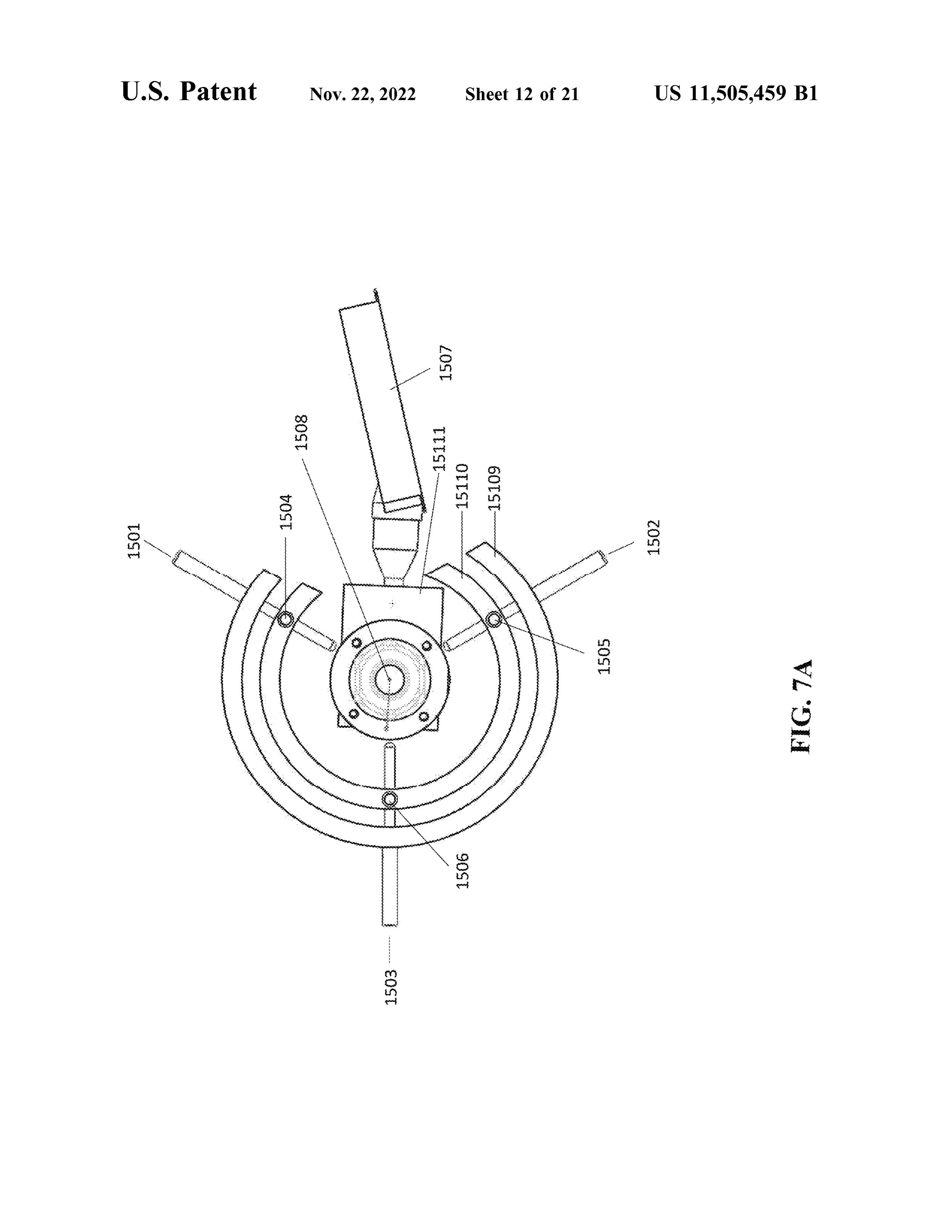
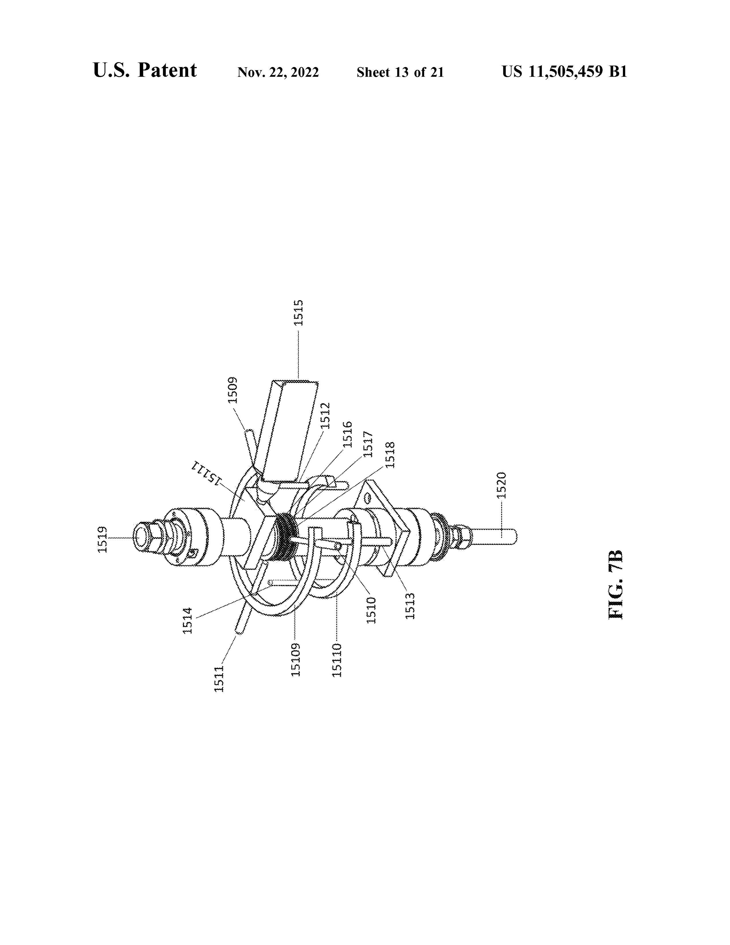
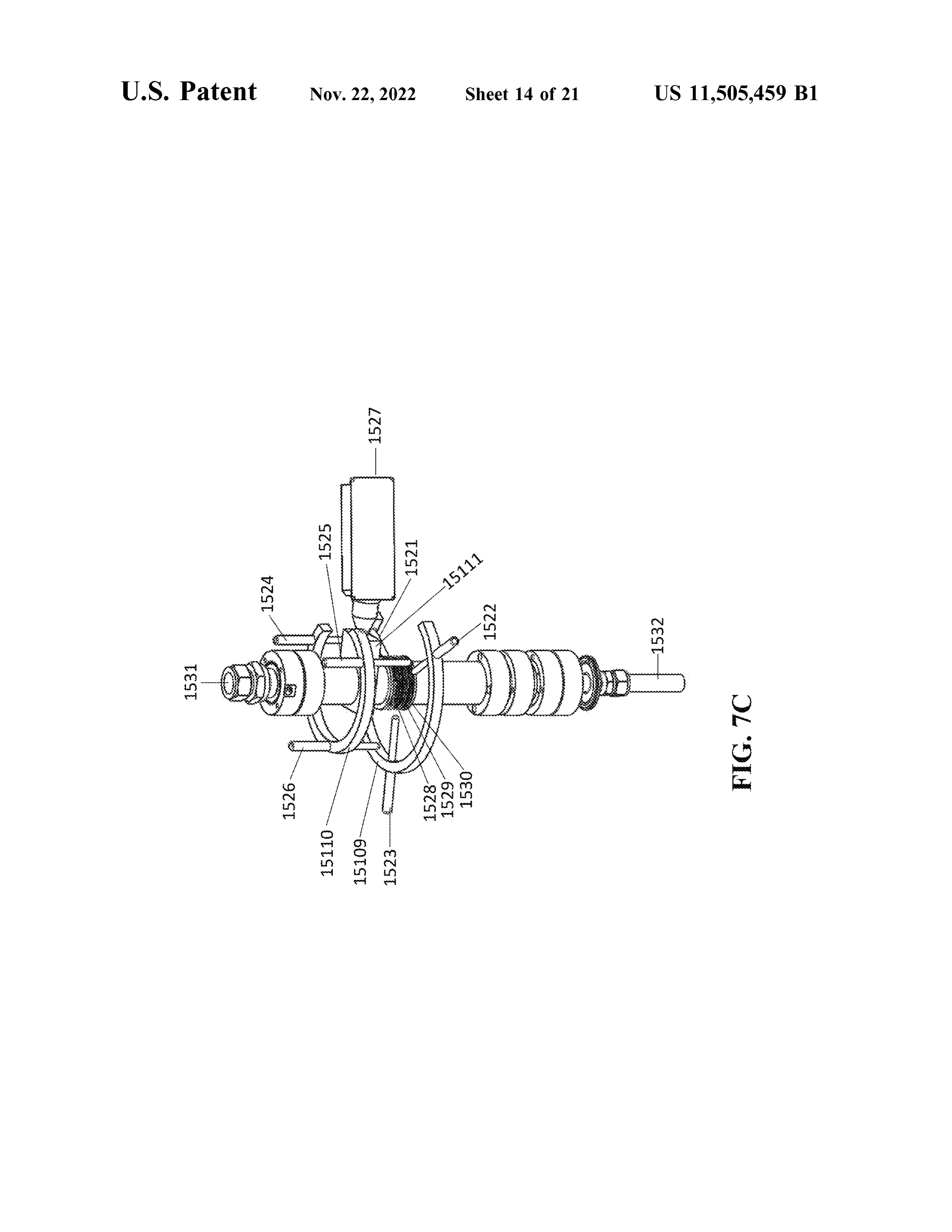
purity of the frits exemplified herein was very high, 99.99 % The reactor can further comprise an X - ray source 211 wt , to ensure that the results obtained cannot be dismissed as (FIG . 2C ) or 424 (FIG . 4B ) and / or one or more lasers 212 the result of contamination. Frits of lower purity and quality (FIG . 2C ) or 426 and 427 ( FIG . 4B ) . Preferred x - ray sources can also be used . The diameter of the porous frit is prefer- 15 include aa mini -x . The x -ray is preferably directed through ably selected to permit a snug fit within the reactor interior, the reactor towards a gas headspace , or target holder 213 , or cup . That is , the diameter of the porous frit is approxi- above the charge material. The X - ray can be directly or mately the same as the inner diameter of the reactor or cup , indirectly provided from the source , such as by reflecting the if present. X -ray from a foil disposed above or below a frit. Referring to FIGS . 6A and 6B , a foil can optionally encase 20 FIG . 7A illustrates a top view of a preferred reactor the chamber containing the charge material on the inside assembly. Pencil lamp 1501 , pencil lamp 1502 and pencil and / or outside of the frits and /or cup , thereby creating a lamp 1503 are shown with the tip directed towards a center metal boundary surrounding the starting material. The foil axis of the reactor assembly along a radius of the reactor can be a metal , such as copper, platinum , niobium , cobalt , assembly. Pencil lamp 1504 , pencil lamp 1505 and pencil gold , silver, or alloys thereof. The foil can also be graphite 25 lamp 1506 are shown directed parallel to a center axis of the or the like. The foil can be between 0 and 0.5 cm thick , reactor assembly and are disposed in a plane along a radius preferably 1-10 mm . The profile of the reactor can be linear of the reactor assembly. Pencil lamp 1501 , together with or it can be configured to contain a constriction below the pencil lamp 1504 , form a first RA lamp pair. Pencil lamp lower frit, providing the general appearance of a lollipop . 1502 , together with pencil lamp 1505 , form second RA The gas line 102 is also shown . 30 lamp pair. Pencil lamp 1503 , together with pencil lamp The reactor chamber is sized to contain the desired 1506 , form a third RA lamp pair. As with the E /MEE pencil amount of charge material 204. For the experiments lamps, each RA lamp can be rotated along its x , y or z axis . described herein , the chamber is designed to contain Each pair can optionally reside within the same radial plane, between 20 mg to 100 grams of nanoporous carbon powder. as shown . Outer support 15109 provides support for the Larger reactors can be scaled up . 35 pencil lamps 1501 , 1502 and 1503. Inner support 15110 The reactor assembly may be augmented with additional provides support for the pencil lamps 1504 , 1505 and 1506 . forms of electromagnetic radiation , such as light. FIG . 4B The outer and inner supports are preferably made of non exemplifies light sources 426 and 427 that generate light conductive materials ( such as polymers or resins ) and are directed through the reactor housing 415 and starting mate- preferably transparent. An optional x - ray source 1507 is rial contained therein . Preferred light sources 426 and 427 40 shown directing X -rays towards the center axis of the reac can be lasers and / or can emit light in a wavelength between tion chamber 1508. Reactor connector 15111 is also shown . 10 nm and 1 mm . The light is optionally subjected to one or FIG . 7B is a perspective view of this reactor assembly. more filters 428 , as shown in the use of light sources (beams) Pencil lamp 1509 , pencil lamp 1510 and pencil lamp 1511 in FIG . 4B . Preferably, the reactor assembly comprises 2 , 3 , are shown directed with the tip towards a center axis of the 4 , 5 or more pairs of lamps disposed circumferentially 45 reactor assembly along a radius of the reactor assembly. The around the RA coils . Pencil lamps, such as the lamps used tip of each lamp aligns with the center, or third , RA coil 1517 within the E/MEE which is incorporated herein by reference and is in the same horizontal plane . Pencil lamp 1512 , pencil from above , are preferred . The pairs of lamps preferably lamp 1513 and pencil lamp 1514 are shown directed parallel define a boundary surrounding the coil and are not touching to a center axis of the reactor assembly, disposed in a plane or otherwise adjacent to the coils . Two lamps are considered 50 along a radius of the reactor assembly and is characterized paired where they are proximal to each other, such as within by a tip pointing towards top of the reactor, away from the the same plane with the center axis of an RA coil . Paired gas inlet 1520. These lamps are illustrated above the hori lamps can be parallel or orthogonal to each other and the RA zontal pencil lamps. The length of each pencil lamp align coil center axis . Lamps can be considered proximal to each with RA coils 1516 , 1517 and 1518. Outer support 15109 other if the space between any two points between the lamp 55 and inner support 15110 support the pencil lamps. An tip and base is within 10 cm , preferably within 5 cm . Lamps optional x - ray source 1515 is shown directing X - rays that are positioned orthogonally to the RA coil center axis towards the center axis of the reactor assembly above the are generally positioned along the line defined by the radius third RA coil 1516. Disposed within the reactor assembly of one or more RA coils . can be a reflecting plate to direct the X - ray towards the The RA lamps, e.g. , the pencil lamps proximal to the 60 reaction chamber. Reactor connector 15111 is also shown, as reactor body, can be matched , or paired , to one or more well as other non -material connectors and spacers . Gas inlet E/MEE lamps, e.g. , the pencil lamps residing within the 1520 and gas outlet 1519 are also shown . E/MEE housing and proximal to the gas line . For example, FIG . 7C is a second perspective view of aa reactor assem where an E /MEE pencil lamp is a neon lamp, a pair of RA bly. Pencil lamp 1521 , pencil lamp 1522 and pencil lamp lamps can be neon pencil lamps. Additionally, where an 65 1523 are shown directed with the tip towards a center axis E/MEE pencil lamp is a neon lamp, a pair of RA lamps can of the reactor assembly along a radius of the reactor assem be neon pencil lamps. Such matched lamps can emit light bly. Pencil lamp 1524 , pencil lamp 1525 and pencil lamp
Page 32
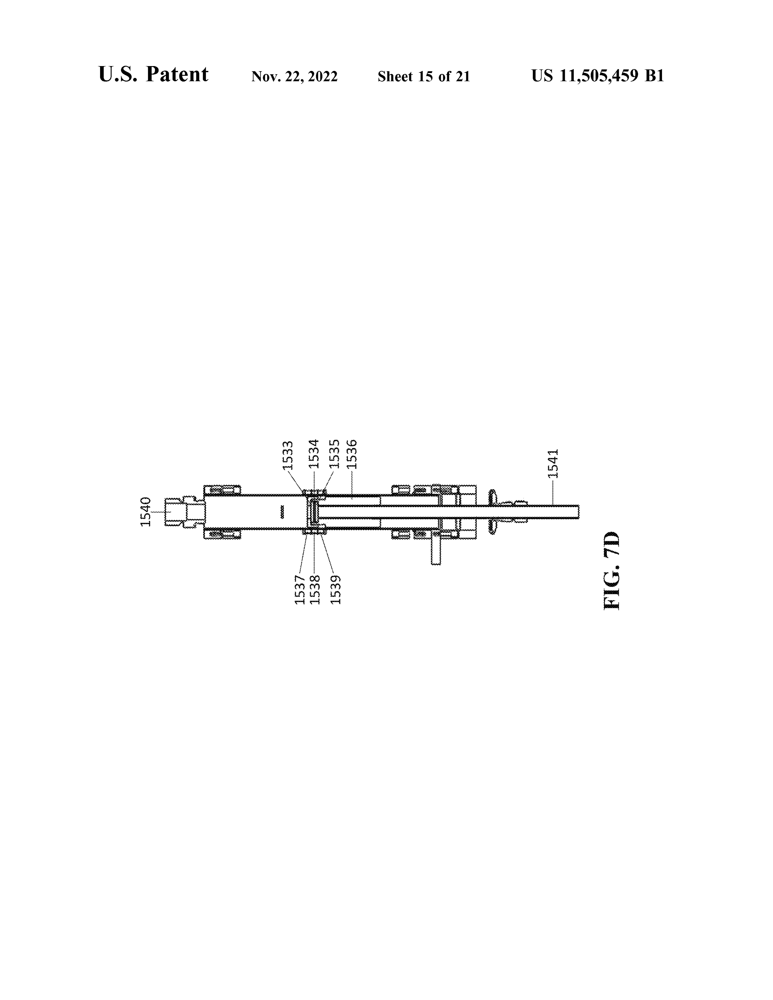
1526 are shown directed parallel to a center axis of the vertically disposed in pairs in radial planes aligned with the reactor assembly, disposed in a plane along a radius of the RA coils . Tips are proximal to RA coils 1585 , 1586 and reactor assembly and is characterized by a tip pointing 1587. X - ray source 1588 directs x - rays towards the center towards the bottom of the reactor, towards the gas inlet axis of the reactor assembly. Supports 15109 and 15110 1532. These vertical lamps are shown above the horizontal 5 support the pencil lamps. Other non -material spacers and lamps and, again , each pair of lamps can optionally lie in the connectors remain unlabeled .
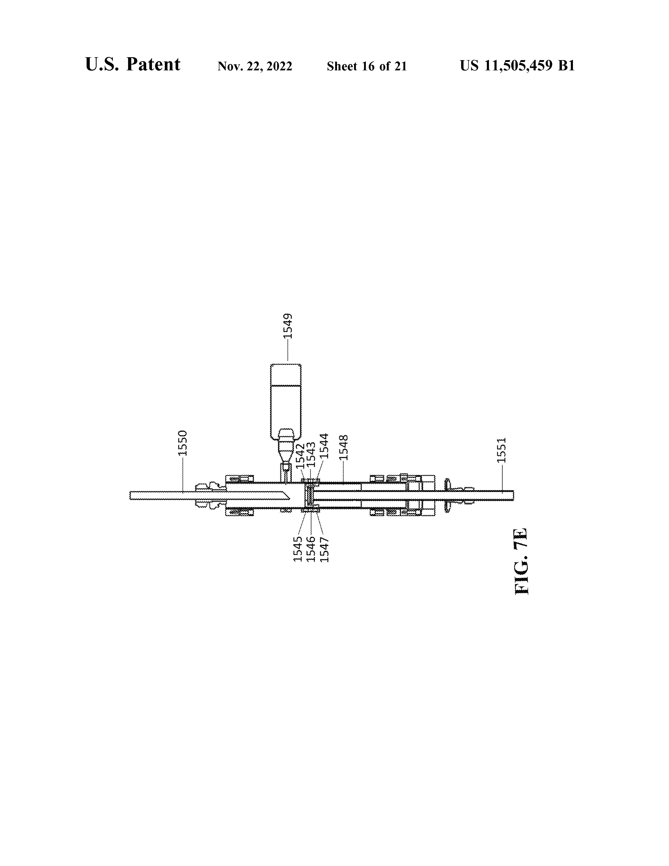
same radial plane. The tip of each pencil lamp aligns with FIG . 71 is a perspective view of a reactor assembly the third RA coil 1528. Outer support 15109 and inner illustrating 5 RA coils , horizontal pencil lamps and an X - ray support 15110 support the pencil lamps. Three RA coils source . Gas enters at the inlet 15107 and exits at outlet 1528 , 1529 and 1530 are shown . An optional x - ray source 10 15108. A first laser 15105 and aa second laser 15106 directing 1527 is shown directing X - rays towards the center axis of the radiation towards the reaction chamber along the axis of the reactor assembly. Disposed within the reactor assembly can reactor assembly is shown . RA coils 1599 , 15100 , 15101 , be aa reflecting plate to direct the X - ray towards the reaction 15102 and 15103 , defining a cylindrical boundary, are chamber. Reactor connector 15111 is also shown, as well as shown . In this embodiment pencil lamps 1593 , 1594 , 1595 , other non -material connectors and spacers . Gas inlet 1532 15 1596 , 1597 , and 1598 are all shown horizontally disposed in and gas outlet 1531 are also shown . pairs in radial planes aligned with the RA coils . Tips are FIG . 7D is a cross sectional side view of the reactor proximal to RA coils 1599 and 15103. X -ray source 15104 assembly, stripped of the pencil lamps and x - ray source . Gas directs x -rays towards the center axis of the reactor assem enters at the inlet 1541 and exits at the outlet 1540. RA coils bly. Support 15109 support the pencil lamps. Other non 1537 , 1538 and 1539 are shown . The first, or bottom , frit 20 material spacers and connectors remain unlabeled . 1535 and the second , or top , frit 1533 contain the reaction Ni - 1 Reactor :
chamber 1534 , which can be charged with nanoporous Referring to FIG . 8A , the reactor body ( 1702 ) is based on carbon powder. The reactor body 1536 is also shown . Other a high purity nickel ( Ni) rod . The Ni rod, with an outside non -material spacers and connectors remain unlabeled . diameter of 15.873 mm (OD ) is bored through then FIG . 7E is a second cross sectional side view of a reactor 25 machined with a female thread on one end. The inside assembly, stripped of the pencil lamps and X - ray source . Gas diameter allows for the installation of upper and lower frit enters at the inlet 1551. RA coils 1545 , 1546 and 1547 are and carbon bed . The carbon reaction medium is housed shown. The first, or bottom , frit 1544 and the second , or top , inside the reactor body ( 1702 ) . To load the reactor, the frit 1542 contain the reaction chamber 1543 , which can be reactor body ( 1702 ) is positioned with the gas discharge charged with nanoporous carbon powder. The reactor body 30 opening ( 1706 ) facing down on a flat surface . A quartz frit 1548 is also shown . X - ray source 1549 directs X - rays ( 1705 ) is placed inside the reactor body ( 1702 ) to form the towards the center axis of the reactor assembly which is then upper containment. 100 mg of carbon is then loaded into the deflected towards the reactor chamber with element 1550 . reactor body ( 1702 ) . After loading of the graphite bed inside Other non -material spacers and connectors remain unla- the reactor body ( 1702 ) , a second quartz frit ( 1703 ) is beled . 35 installed . A reactor pole ( 1701 ) , machined out of a high FIG . 7F is a second cross sectional side view of a reactor purity graphite rod with matched male threads for the reactor assembly with the pencil lamps and x - ray source . Gas enters body ( 1702 ) , is then screwed onto the reactor body ( 1702 ) . at the inlet 1564. RA coils 1555 , 1556 and 1557 are shown . The reactor pole ( 1701 ) is designed to provide the identical The first, or bottom , frit 1554 and the second , or top , frit graphite bed compression as that provided by the cup design 1552 contain the reaction chamber 1553 , which can be 40 ( 1708 ) .
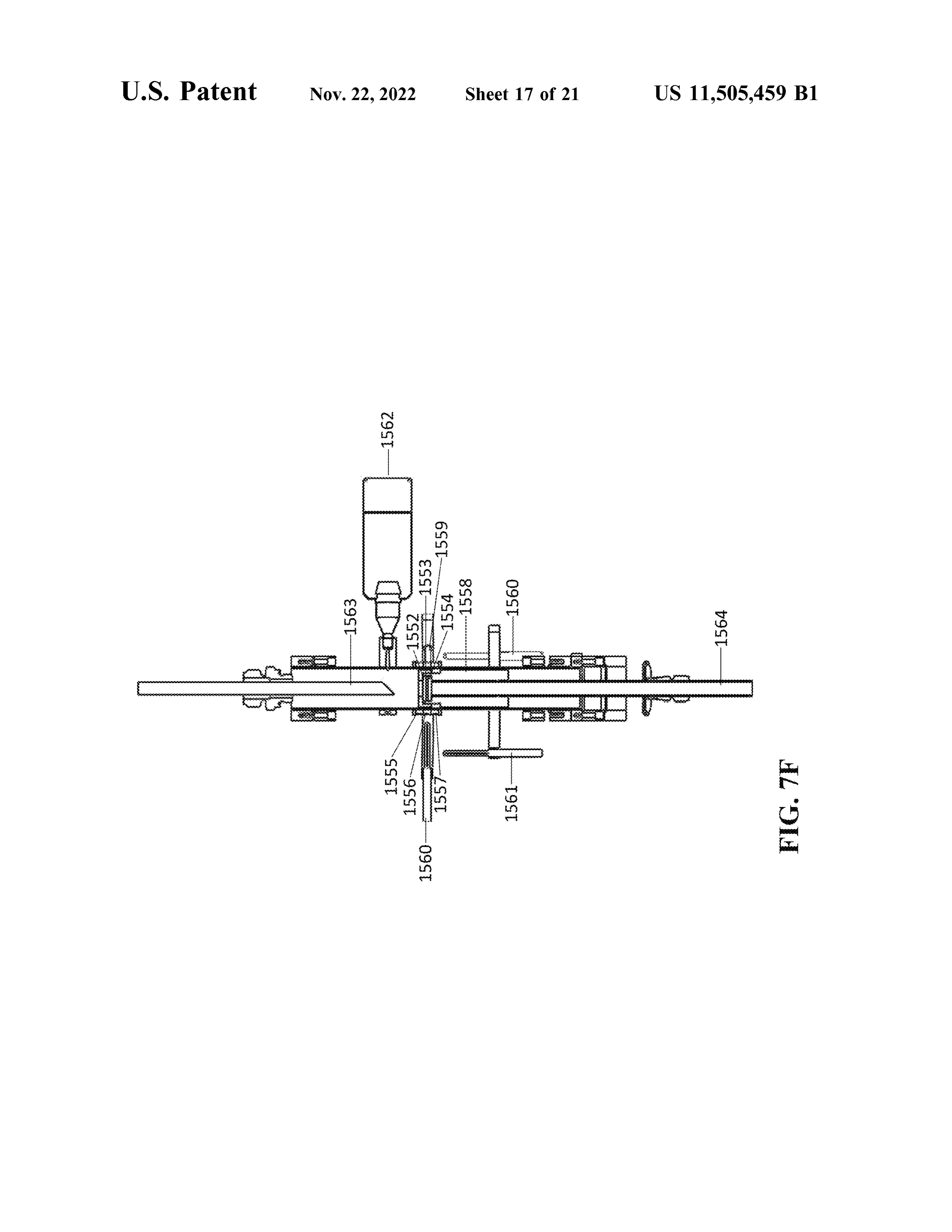
charged with nanoporous carbon powder. The reactor body NiPtG Reactor :
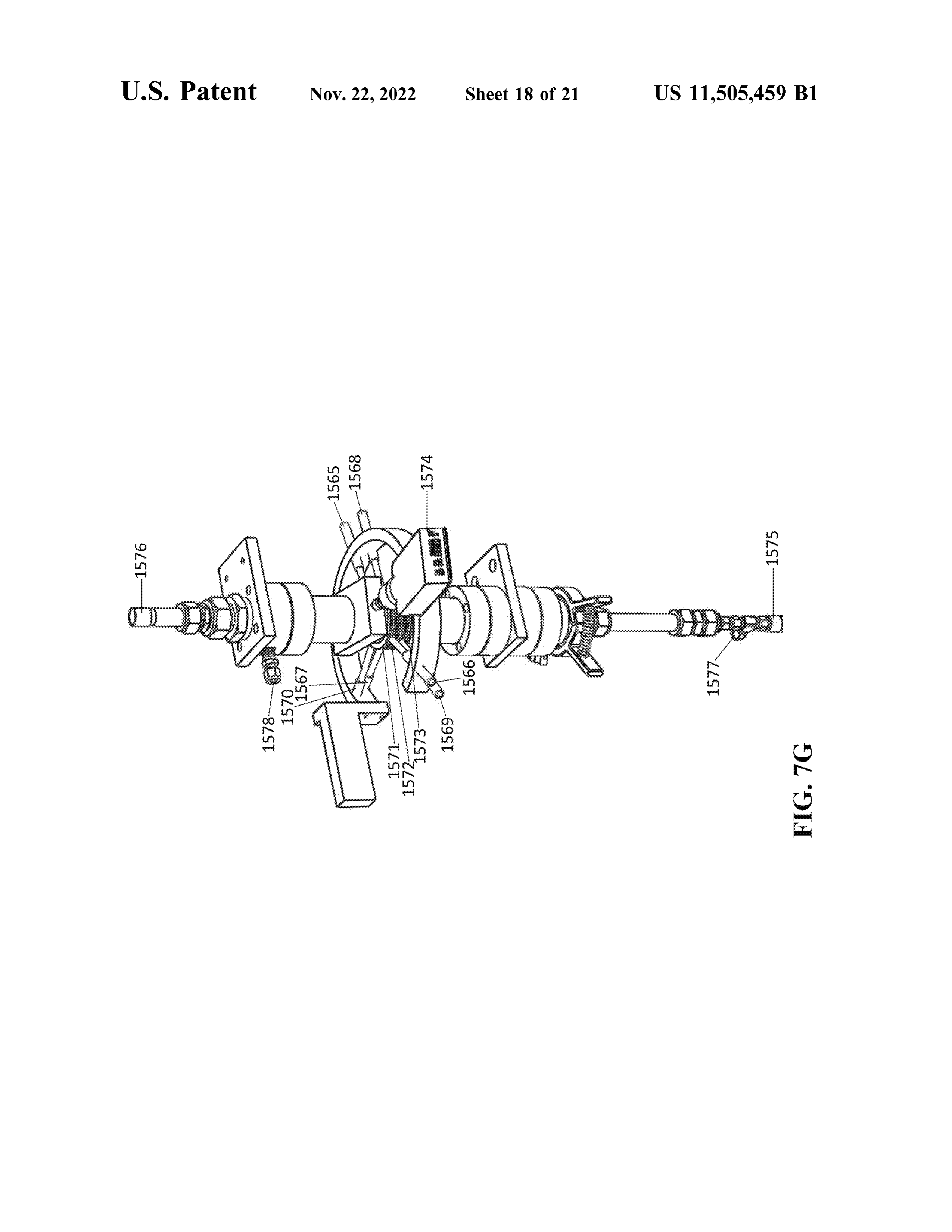
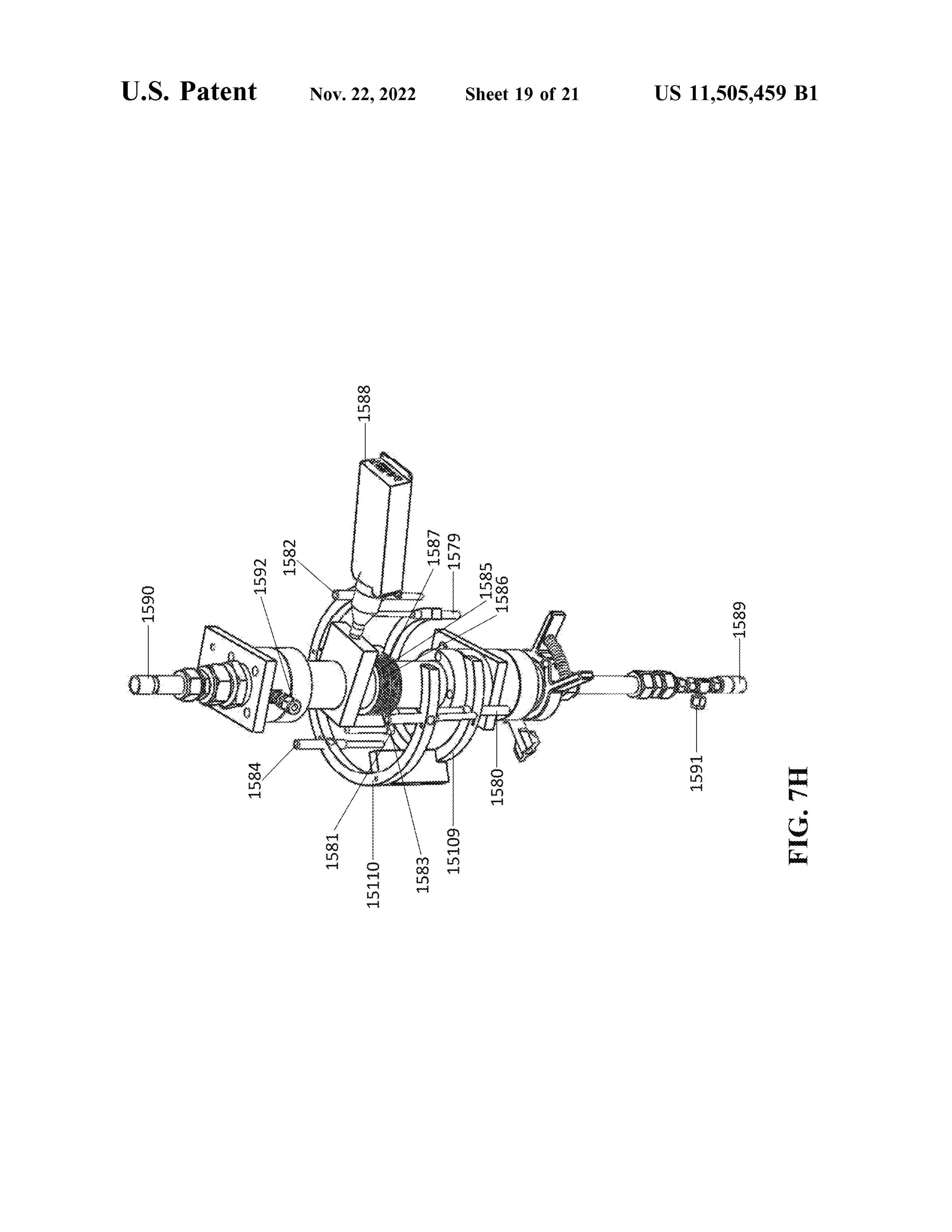
1558 is also shown . Vertical pencil lamps 1560 and 1561 are Referring to FIG . 8B , in the NiPtG Reactor embodiment, shown as are horizontal pencil lamps 1560 and 1559. X - ray the reactor body ( 1707 ) is based on a high purity nickel (Ni) source 1562 directs x - rays towards the center axis of the rod. The Ni rod, with an outside diameter of 15.873 mm reactor assembly which is then deflected towards the reactor 45 (OD ) is bored through then machined on one end to have an chamber with element 1563. Other non -material spacers and inside diameter of 11.68 mm (ID ) . The inside diameter connectors remain unlabeled . allows for the installation of a graphite cup ( 1708 ) and an FIG . 7G is a perspective view of a reactor assembly with optional 0.025 mm platinum ( Pt) foil ( 1713 ) . The graphite the pencil lamps and x - ray source . Gas enters at the inlet cup provides for reactor wall and foil isolation from the 1577 and exits at outlet 1578. A first laser 1575 and a second 50 carbon bed . The carbon reaction medium is housed inside a laser 1576 directing radiation towards the reaction chamber 99.9999 wt % pure graphite cup ( 1708 ) . To load the reactor, along the axis of the reactor assembly is shown . RA coils a quartz frit ( 1709 ) is placed inside the graphite cup ( 1708 ) 1571 , 1572 and 1573 are shown . In this embodiment pencil to form the bottom containment. 100 mg of carbon ( 1710 ) is lamps 1565 , 1566 , 1567 , 1568 , 1569 , and 1570 are all shown then loaded into the cup ( 1708 ) . After loading of the graphite horizontally disposed in pairs along the radius towards the 55 bed inside the cup , a second quartz frit ( 1711 ) is installed ; reactor assembly central axis . Tips are proximal to RA coils this system is defined as the cup assembly. Prior to installing 1571 , 1572 and 1573. X - ray source 1574 directs x - rays the cup assembly, the foil ( 1713 ) is used to line the inside towards the center axis of the reactor assembly. Support surface of the reactor wall . The cup assembly is then placed 15109 supports all of the horizontal pencil lamps. Other within the nickel reactor body ( 1707) and foil ( 1713 ) . After non -material spacers and connectors remain unlabeled . 60 the cup assembly is installed , a 99.9999 wt % pure graphite FIG . 7H is a perspective view of a reactor assembly with cap ( 1712 ) is screwed onto the reactor body. The cap secures the pencil lamps and X - ray source . Gas enters at the inlet the cup from movement after assembly . The figure addition 1591 and exits at outlet 1592. A first laser 1589 and a second ally is illustrative of the GG Reactor configuration . laser 1590 directing radiation towards the reaction chamber PtirGG Reactor :
along the axis of the reactor assembly is shown . RA coils 65 Referring to FIG . 8C , the reactor body ( 1714 ) is based on 1585 , 1586 and 1587 are shown . In this embodiment pencil a high purity graphite rod. The graphite rod, with an outside lamps 1579 , 1580 , 1581 , 1582 , 1583 , and 1584 are all shown diameter of 15.873 mm (OD ) is bored through then
Page 33
machined on one end to have an inside diameter of 11.68 the boundaries of the system , by selecting the reactor mm (ID ) . The inside diameter allows for the installation of materials and adding a foil layer can also enhance the a graphite cup ( 1715 ) for reactor wall isolation from the harmonics.
carbon bed . The carbon reaction medium is housed inside a In particular, the invention includes processes of produc 99.9999 wt % pure graphite cup ( 1715 ) . To load the reactor, 5 ing , or instantiating, nanoporous carbon compositions com a quartz frit ( 1716 ) is placed inside the graphite cup to form prising the steps of:
the bottom containment. 100 mg of carbon ( 1717) is then adding a nanoporous carbon powder into a reactor assem packed into the cup . After loading of the graphite bed inside bly as described herein ;
the cup , a second quartz frit ( 1718 ) is installed ; this system adding a feed gas to the reactor assembly; is defined as the cup assembly. The cup assembly is then 10 powering the one or more RA coils to a first electromag placed within the graphite reactor body ( 1714 ) . After the cup netic energy level ;
assembly is installed , a cap ( 1719 ) composed of platinum heating the nanoporous carbon powder; and 10 % wt iridium is screwed onto the reactor body. The harmonic patterning the nanoporous carbon powder cap secures the cup from movement after assembly. between a first electromagnetic energy level and a second The residence time of the starting material within the 15 electromagnetic energy level for aa time sufficient to instan reactor is effective to instantiate product into the starting tiate hydrogen in a nanopore and, optionally, collecting the material and can be between 0 and 15 minutes . hydrogen .
Preferred reactors used in the methods of the invention are The invention includes a process for producing a product shown in the table below. gas comprising the steps of:
Reactor Cup Cap Reactor Pole Chamber Coil
ID Material Material Material Material Boundary Capacity Type
CgF N/A N /A Cu , Ni or graphite N /A 100 mg Induction
graphite
CuG Graphite graphite Cu quartz N /A 100 mg Induction
Frequency
PtIrGG Graphite Pt/ Ir graphite quartz NA 100 mg Induction
GPG Graphite graphite graphite quartz Pt 100 mg Induction
Frequency
GPtGPtG Graphite graphite graphite quartz 2X Pt 100 mg Induction
GG - EL Graphite graphite graphite quartz N /A 3g or
Frequency
Foil ( Pt) Graphite graphite graphite quartz Pt 100 mg Induction
Frequency
GZ Foil Graphite graphite graphite quartz Nb, Co 100 mg Induction or , any
Frequency nzG Foil Graphite Any Z graphite quartz Ir 100 mg Induction
Frequency
NiG Graphite graphite Ni quartz N /A 100 mg Induction
Frequency
NiPtG Graphite graphite Ni quartz Pt 100 mg Induction
ZG N / A Pd / Ru or graphite quartz N/A 100 mg Induction any z
Ref- X Graphite graphite graphite quartz NA 1-20 g Frequency
( a) adding a feed gas to an electromagnetic embedding
The invention further relates to methods of instantiating apparatus:
materials in nanoporous carbon powders. It has been sur- (b ) exposing the feed gas to at least one E/MEE light prisingly found that light elements, such as hydrogen , oxy- source ;
( c ) directing the feed gas from step ( b ) to a reactor gen , helium , and the like are instantiated . Instantiating is 55 assembly defined herein to include the nucleation and assembly of comprising:
atoms within carbon structures, particularly , ultramicropo A gas inlet and one or more gas outlets ; res . Without being bound by theory, it is believed instantia A reactor chamber containing a nanoporous carbon dis tion is related to , inter alia , degrees of freedom of the posed within a cup and, optionally, covered with a cap ; electromagnetic field as expressed by quantum field theory. 60 A first porous frit defining a floor of the reactor chamber disposed within the cup ,
By exposing a gas to harmonic resonances, or harmonics, of A second porous frit defining the ceiling of the reactor electromagnetic radiation within one or more ultramicropo- chamber ; wherein each porous frit has a porosity that is res , vacuum energy density is accessed and allows for the sufficient to allow a gas to permeate into the reactor nucleation and assembly of atoms . Electromagnetic energy chamber;
that is within the frequencies of light, X - rays , and magnetic 65 A reactor head space disposed above the reactor chamber; fields subjected to frequency generators can enhance the At least one RA coil surrounding the reactor chamber formation and maintenance of such harmonics. Modifying and / or reactor head space operably connected to a
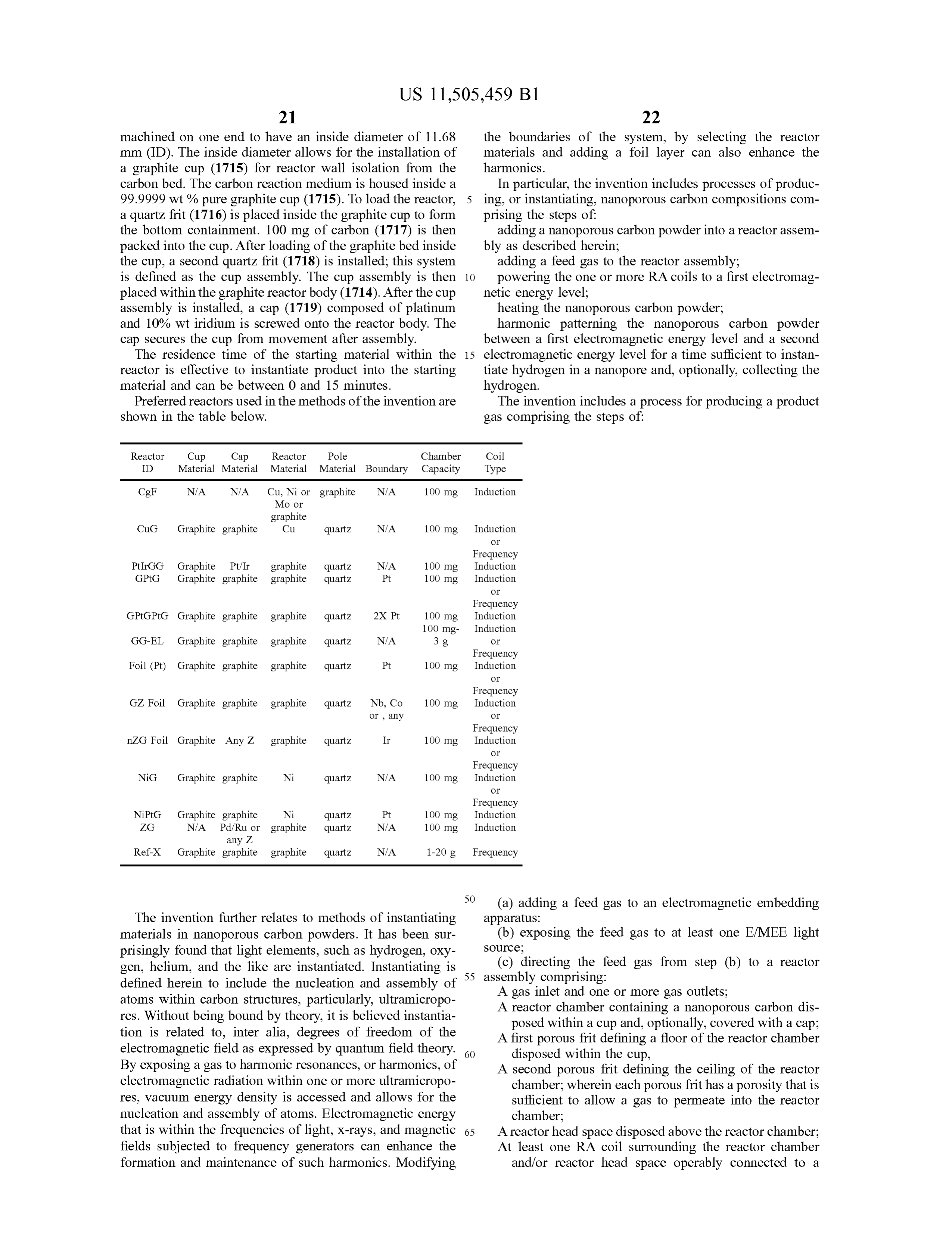
Page 34
power supply, wherein the computer processing unit is The invention permits the manufacture of green gas , such configured to control the power supply to the RA coil ; as product gas that has less than 0.5 % vol CO2 , such as less ( d ) subjecting the nanoporous carbon powder to harmonic than 100 ppm CO2 .
patterning to instantiate hydrogen; The hydrogen can be isolated from , or purified, the ( f) collecting the product gas comprising the hydrogen; 5 product gas , thereby producing a high concentration hydro and gen gas . An example of a purification system utilizing a (g ) isolating the hydrogen from the product gas . hydrogen - selective membrane. Examples of suitable mate The term " harmonic patterning ” is defined herein as rials for membranes include palladium and palladium alloys , oscillating between two or more energy levels ( or states ) a and especially thin films of such metals and metal alloys . plurality of times . The energy states can be characterized as 10 dium Palladium alloys are particularly effective, especially palla with 35 weight % to 45 weight % copper. Another a first, or high , energy level and a second , or lower, energy effective level . The rates of initiating the first energy level , obtaining gold, suchalloy is palladium with 2 weight % to 10 weight % the second energy level and re - establishing the first energy selective membranes canwith as palladium 5 weight % gold . Hydrogen level can be the same or different. Each rate can be defined 15 natively or additionally a pressure swing toadsorption be configured be a foil. Alter system in terms of time , such as over 1 , 2 , 3 , 4 , 5 , 6 , 7 , 8 , 9 , 10 or can be used to concentrate hydrogen and remove unwanted more seconds . Each energy level can be held for a period of gases . Such processes use activated carbon, silica or zeolites . time , such as 1 , 2 , 3 , 4 , 5 , 6 , 7 , 8 , 9 , 10 or more seconds.
Harmonic patterning is continued until instantiation is Ex . 1 : Energy /Light Combed Activation (E/ LC ) achieved . 20
Where two more electromagnetic radiation sources are One hundred milligrams ( 100 mg) of powdered carbon present (e.g. , coils , X - ray source , lasers, and /or lamps), each was placed in a GG - EL graphite tubular reactor ( 15.875 mm) can be subjected to harmonic patterning and the patterning OD , with ID machined to ~ 9 mm ). This reactor was inserted can occur independently, simultaneously or sequentially. into a reactor assembly FIG . 2A and then placed into a high The process further comprises independently powering 25 vacuum oven for degassing according to the Degassing any additional electromagnetic radiation source , as Procedure ( See Profile 1 or Profile 2 ) . After degassing , the described above in the E/MEE apparatus or reactor assem reactor assembly is transferred to a test cell for processing. bly . For example, the process further comprises the step ( s) Research - grade Nitrogen (N2) was delivered at 2 SLPM to of powering RA frequency generator ( s) connected to one or 30 purge gases the system for a minimum of 25 seconds or more . The were fed through the E /MEE in aa horizontal and level more RA coils , one or more lamps or lasers , X - ray sources , gas line , as described above . During purging, gas sampling induction coils , E / MEE coils , and the like substantially as lines are also purged. TEDLAR® sealed bags , when used , described above . are connected to the sampling lines during the purge cycle . The invention particularly relates to the identification and Referring to FIG . 1 , the argon “ KC ” light 108 located in collection of a product gas produced by the methods. The 35 position product gas can be collected from the process in a continu entrance 0flange( vertical lamp orientation; 7.62 cm from inlet or ; at 180 ° ; bulb tip pointing up 2.54 cm from ous , semi- continuous or batch manner. The product gas the outer diameter of the gas line ) was turned on at the onset typically comprises the feed gas ( or first gas composition , as while simultaneously energizing the power supply to 5 discussed above) and a second gas composition , comprising amps. This light was kept on for a minimum hold time of 9 hydrogen. The second gas composition is distinct from the 40 sec. Next light 109 in position 1 ( 109 ; horizontal lamp first gas composition and preferably contains one or more orientation ; 7.62 cm from inlet or entrance flange; at 180 ° ; gases not present in the feed gas . For example, where the bulb tip facing exit plate ; bulb glass base at the optical feed gas is pure nitrogen (e.g. , aa gas comprising at least 99 % entrance ; 5.08 cm , from the outer diameter of the gas line) , vol nitrogen , such as at least 99.9 % vol nitrogen ), such as a a krypton light, was turned on and the power is increased to nitrogen gas with less than 1 % hydrogen, the product gas 45 10 amps on the power supply . This was held for 3 seconds, will contain one or more other materials (e.g. , elements or light 107 , in position 1 ( 107 ; horizontal lamp orientation ; at molecules that exist in gas form under ambient conditions ), 0 ° ; bulb tip at the optical exit facing the exit plate; 5.04 cm preferably hydrogen . The feed gas can also include air. The from the outer diameter of the gas line) , a xenon light was product gas comprises hydrogen and an additional gas such turned on and held for 9 seconds and the power was as helium , water, neon , nitrogen , carbon monoxide, oxygen , 50 increased to 15 amps. After these 3 lights have been sequen argon , carbon dioxide , fluorocarbons, ammonia , krypton, tially turned on , the sealed TEDLAR® bags are opened for xenon , methane and other hydrocarbons or organics and gas collection , and the amperage delivered to reactor was mixtures thereof. “ Product gas ” is defined herein as being adjusted to 100 amps and held for a minimum of 30 seconds . compositionally distinct different from the term “ Feed gas " Immediately after the power was increased light 103 in and explicitly excludes air. 55 position 1 ( 103 ; vertical lamp orientation; 7.62 cm from inlet Preferred product gases comprise at least about 1 % vol or entrance flange; at 0 ° ; bulb tip pointing down 2.54 cm ( preferably at least about 4 % vol ) hydrogen. Preferably, from the outer diameter of the gas line) , a neon light, was product gases will further comprise neon, helium , argon and turned on.
combinations thereof. Typically, the product gas will further Amperage harmonic patterning was then initiated on the comprise the components found in the feed gas ( e.g. , nitro- 60 reactor. With each amperage pattern (oscillation) , the gases gen or air) , however, in concentrations distinct therefrom . A fed to the reactor can treated by the same or different light preferred product gas comprises nitrogen, hydrogen and a sequence. In one embodiment of the experimental protocol, gas selected from neon , helium , argon and combinations the amperage of the reactor was increased to 78.5 amps over thereof. A preferred product gas comprises nitrogen, hydro- 1 second, the high - end harmonic pattern point. The amper gen , oxygen and a gas selected from neon , helium , argon and 65 age of the reactor was then decreased to 38.5 amps over 9 combinations thereof. A preferred product gas comprises at seconds and held at 38.5 amps for 3 seconds . Immediately least 1 % vol helium , argon , neon and combinations. at the start of the 3 second hold , an argon light 122 in
Page 35
position 1 ( 122 ; horizontal lamp orientation ; at 180 ° ; bulb pump and begin the degassing protocol. Maintained the tip pointing towards entrance plate at the optical entrance ; temperature and vacuum for 12 hours. After the 12 hours, 5.04 cm from the outer diameter of the gas line ) was turned allowed the oven to cool prior to closed end unit removal. on . After the 3 second hold , amperage to the reactor was then Example 3 : Degassing Profile 2 ramped up to 78.5 amps over 9 seconds with aa 3 second hold 5 upon reaching 78.5 amps before a downward ramp was initiated . The reactor amperage was decreased to 38.5 amps , One hundred milligrams ( 100 mg) of powdered carbon over 9 seconds and then held for 3 seconds. Immediately at was placed in a graphite tubular reactor ( 15.875 mm ) OD , the start of the 3 second hold , light 103 ( 103 ) , a neon light with ID machined to ~ 9 mm ), as described above and loaded in position 1 , was turned on . The reactor amperage was 10 into aa closed end system . After ten closed end set - ups have again ramped up to 78.5 amps over 9 seconds , held there for been completed, each individual unit was loaded into the 3 seconds , and then again ramped down to 38.5 amps over degassing oven openings and connected all incoming and 9 seconds . A long -wave ultraviolet lamp ( 104 ; horizontal outgoing lines to the closed end systems. Isolated each lamp orientation ; at 90 ° ; bulb tip facing entrance plate at the incoming line to each reactor while maintaining the outgo optical entrance; 5.04 cm from the outer diameter of the gas 15 ing lines in an open position . Started the vacuum system line) in position 1 was turned on . until the vacuum gauge reads at least 750 mmHg. Upon The reactor was again ramped up to 78.5 amps over 9 reaching 750 MmHg, closed all outgoing line valves from seconds, held for 3 seconds , then decreased to 38.5 amps the closed end systems and secured the vacuum pump . over another 9 seconds . Next aa short - wave ultraviolet lamp Performed a 30 -minute leak test of the system . After suc ( 105 horizontal lamp orientation ; 7.62 cm from inlet or 20 cessfully passing the leak check , opened each incoming line entrance flange; at 270 ° ; bulb tip at the optical entrance and to the closed end system one at a time at 0.4 SLPM N2 . Once .
facing the entrance plate ; 5.04 cm from the outer diameter all incoming lines were open and the vacuum gauge reached of the gas line) in the E/ MEE (position 1 ) E/MEE section a slight positive pressure , opened the gas outgoing gas line light was turned on and held for 3 seconds . The reactor was on the degassing oven . Started the degassing oven profile again ramped up to 78.5 amps over 9 seconds and held for 25 ramping from 200 ° C. - 50 ° C. to 400 ° C. over 1 hour while 3 seconds . After the 3 second hold , the reactor amperage was maintaining N, flow .After the 1 - hour ramp , maintained flow decreased to 38.5 amps over another 9 seconds . The reactor for an additional hour for temperature stabilization while was then held at 38.5 amps for 3 seconds , before another maintaining gas flow . After the temperature stabilization was ramp up to 78.5 amps over 9 seconds was initiated . At 3 complete , secured all incoming gas flows and isolated the seconds into this ramp, lamp 107 , in position 1 (107) was 30 degassing oven vent line . Immediately started the vacuum turned on and held there for the remaining 6 seconds of the pump and began the degassing protocol. Maintained the 9 second total ramp. The reactor was held for 3 seconds in temperature and vacuum for 12 hours. After the 12 hours , this condition . allowed the oven to cool prior to closed end unit removal. The lights were turned off simultaneously in the E/MEE Example 4 : Gas Analysis section as follows: ( 103 ) , ( 108 ) , ( 106 ) , ( 105 ) and ( 104 ) and 35 the reactor was deenergized. The reactor was held at this For the chemical analysis of gas samples in TEDLAR® state , with continuous gas flow for 27 seconds during which the TEDLAR® bags are closed and removed . All remaining bags , a test protocol was developed based on the standard lights were turned off and gas flow continues for 240 40 cally - sealed established test method for internal gas analysis of hermeti devices . Prior to sample measurement, system seconds.
background was determined by following exact measure
Example 2 : Degassing Profile 1 ment protocol that is used for sample gas . For system background and sample , a fixed volume of gas was intro
One hundred milligrams ( 100 mg ) of powdered carbon duced to the Pfeiffer QMA 200M quadrupole mass spec was placed in a graphite tubular reactor ( 15.875 mm) OD , 45 trometer (QMS ) system through a capillary. Through a with ID machined to ~ 9 mm ), as described above and loaded capillary, a fixed volume of gas was introduced to the into a closed end system . After ten closed end set -ups have Pfeiffer QMA 200M quadrupole mass spectrometer ( QMS ) been completed, each individual unit was loaded into the system . After sample gas introduction, the ion current for degassing oven openings and all incoming and outgoing specific masses ( same as masses analyzed for system back lines were connected to the closed end systems. Isolated 50 ground) were measured. During background and sample gas each incoming line to each reactor while maintaining the analyses total pressure of the QMS system was also outgoing lines in an open position . Started the vacuum recorded , allowing for correction of the measured ion cur system until the vacuum gauge reads at least 750 mmHg. rent.
Upon reaching 750 MmHg, closed all outgoing line valves from the closed end systems and secured the vacuum pump . 55 TABLE 1 Performed a 30 -minute leak test of the system . After suc Gases analyzed for the test method and measured cessfully passing the leak check , opened each incoming line masses used in deconvolution . to the closed end system one at a time at 0.4 slpm N2 . Once all incoming lines were open and the vacuum gauge reached Gas Masses used for deconvolution a slight positive pressure , opened the outgoing gas line on 60 1. Hydrogen 2 , 18 , 55 , 57 the degassing oven . Started the degassing oven profile 2. Helium ( 3 ) 2, 4 ramping from Tamb to 400 ° C. over 1 hour while maintaining 3. Helium (4) 4. Methane
N2 flow . After the 1 -hour ramp, maintained flow for an 5. Water 18 , 32 , 40 additional hour for temperature stabilization while maintain 6. Neon ( 20 ) 18 , 20 , 40 ing gas flow . After the temperature stabilization was com- 65 7. Neon (22 ) 20 plete , secured all incoming gas flows and isolated the 8. Nitrogen 14 degassing oven vent line . Immediately started the vacuum
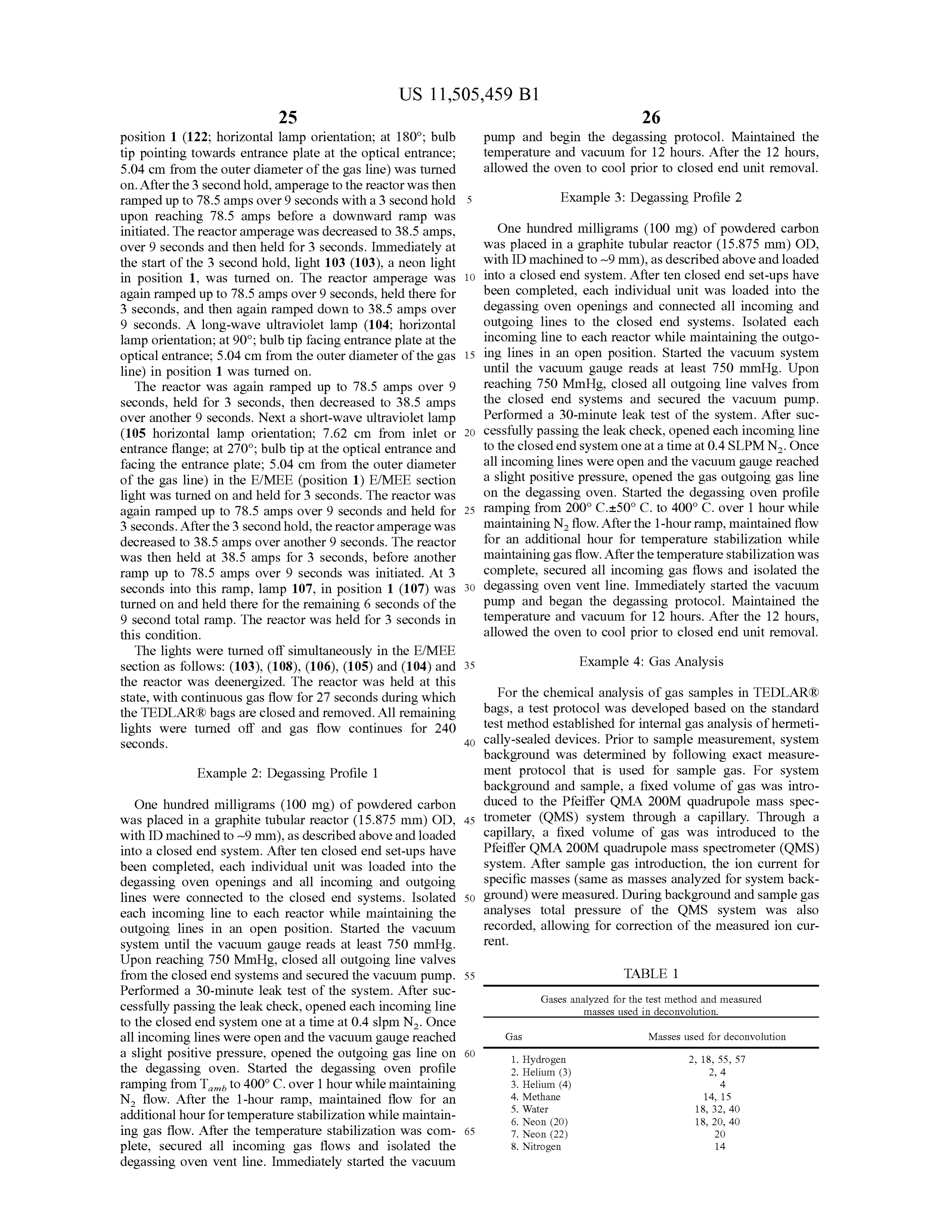
Page 36
TABLE 1 - continued -continued
Gases analyzed for the test method and measured Protocol 1 :
masses used in deconvolution .
5 Methane (CH4) 0 0 0
Gas Masses used for deconvolution Water (H2O) 0.4054 1.0773 0 Neon (20) 0.036 0.03 0.0417 9. Carbon Monoxide 14 , 28 Neon (22) 0.0036 0.003 0.0042 10. Oxygen 32 Nitrogen 95.276 89.3705 99.347 11. Argon 40 , 41 , 43 Carbon Monoxide (CO ) 0 0 0 12. Carbon Dioxide 44 Oxygen 3.1604 8.5606 0.3796 13. Tot. HC and Org. 55 , 57 10 Argon 0.0676 0.349 0.0003
Carbon Dioxide (CO2) 0.0138 0 0
Total Hydrocarbons 0.0269 0 0.0175 16. Krypton 84 and Organics 17. Xenon 132 Fluorocarbons 0.0261 0.0417 0.0162 Ammonia (NH3) 0 0.031 0 15 Krypton 0.0242 0 0
Data Analysis: Xenon 0 0 0 Measurements of the ion current for each mass were corrected to the average of measured background contribu- Gases Analyzed (Vol % ) Ill . 4 Ill . 5 Ill . 6 tions corrected for pressure difference . Subsequent to the Hydrogen 0 0.0162 1.027 background correction , individual corrected mass signals 20 Helium (4) 0.5476 0.1254 0.364 were averaged and corrected to a known gas standard to Methane (CH4) 0 0 0 determine the percent volume of 17 gas species . All correc- Water (H20) 0 0 0 tions were determined using nitrogen and nitrogen -hydrogen Neon (20) 0.1789 0.0345 0.1093 mixture reference gases analyzed to match selected process Neon (22) 0.0179 0.0035 0.0109 gas for test samples using the developed protocol based on Nitrogen
Carbon Monoxide (CO )
the standard test method, in accordance with Military Stan- 25 Oxygen 10.945 0.1826 1.2975 dard ( MIL - STD - 883 ) Test Method 1018 , Microcircuits, Argon 0.08 0 0 Revision L , FSC / Area : 5962 (DLA , 16 Sep. 2019 ) . Results Carbon Dioxide (CO2 ) 0 0 0 below : 1 % = 10,000 ppm , Volume values for gas blanks and Total Hydrocarbons and
Organics
samples were produced using the developed gas analysis test
Fluorocarbons 0.0127 0 method and validated using a gas mixture standard of 30 Ammonia 99.98% nitrogen and 0.02 % hydrogen . All analytical per Krypton (NH3) formed by EAG Laboratories, Liverpool, N.Y. using stan- Xenon dard TEDLAR® bag gas sampling protocols and specified Gases Analyzed ( Vol % )
mass spectrometry methods.
Mass Analyzer: Quadrupole mass spectrometer ( Pfeiffer 35 Hydrogen 0 0 4.0494 QMA 200M) Helium ( 4 ) 2.6033 0.2145 25.118 Measurement mode : Analog scan for selected masses Methane (CH4) 0 0 0 No. of channels used : 64 Water (H2O) 0 0 0 Neon (20) 0.4736 0.0308 5.6369
Mass resolution : Unit resolution Neon (22) 0.0474 0.0031 0.5637 Maximum detectable concentration : 100% 40 Nitrogen 94.6204 95.9834 56.538 Minimum detectable concentration : 1 ppb Carbon Monoxide (CO ) 0 0 0 Background vacuum : <2x10⁻⁶ Torr Oxygen 2.2553 3.7604 4.1726 Results : Argon 0 0.0078 0 Carbon Dioxide (CO2) 0 0 0
Total Hydrocarbons and 0 0 1.0654 45 Organics
Protocol 1 :
Fluorocarbons 1.9565
Gases Analyzed ( Vol % )
Hydrogen
Helium (4 )
Ammonia (NH3)
Krypton
Xenon
Protocol 2 :
Gases Analyzed ( Vol. % ) Ill . 10 Ill . 11 Ill . 12 Ill . 13 Ill . 14 Ill . 15
Hydrogen 0 1.0428 1.3437 0 1.6249 1.7941
Helium ( 4 ) 0.4679 0.3492 0.4409 0.8074 0.4888 0.6406
Methane (CH4) 0 0 0 0 0 0
Water (H20) 0 2.3924 3.1436 0 4.4032 2.4182
Neon (20) 0.1598 0 0 0 0 0
Neon (22) 0.016 0 0 0 0 0
Nitrogen 76.7986 79.9798 94.2126 51.1046 92.2167 75.6209
Carbon Monoxide 0 0 0 0 0 0
Oxygen 22.079 15.565 0.8348 48.088 1.239 18.7733
Argon 0.4639 0.5717 0 0 0 0.721
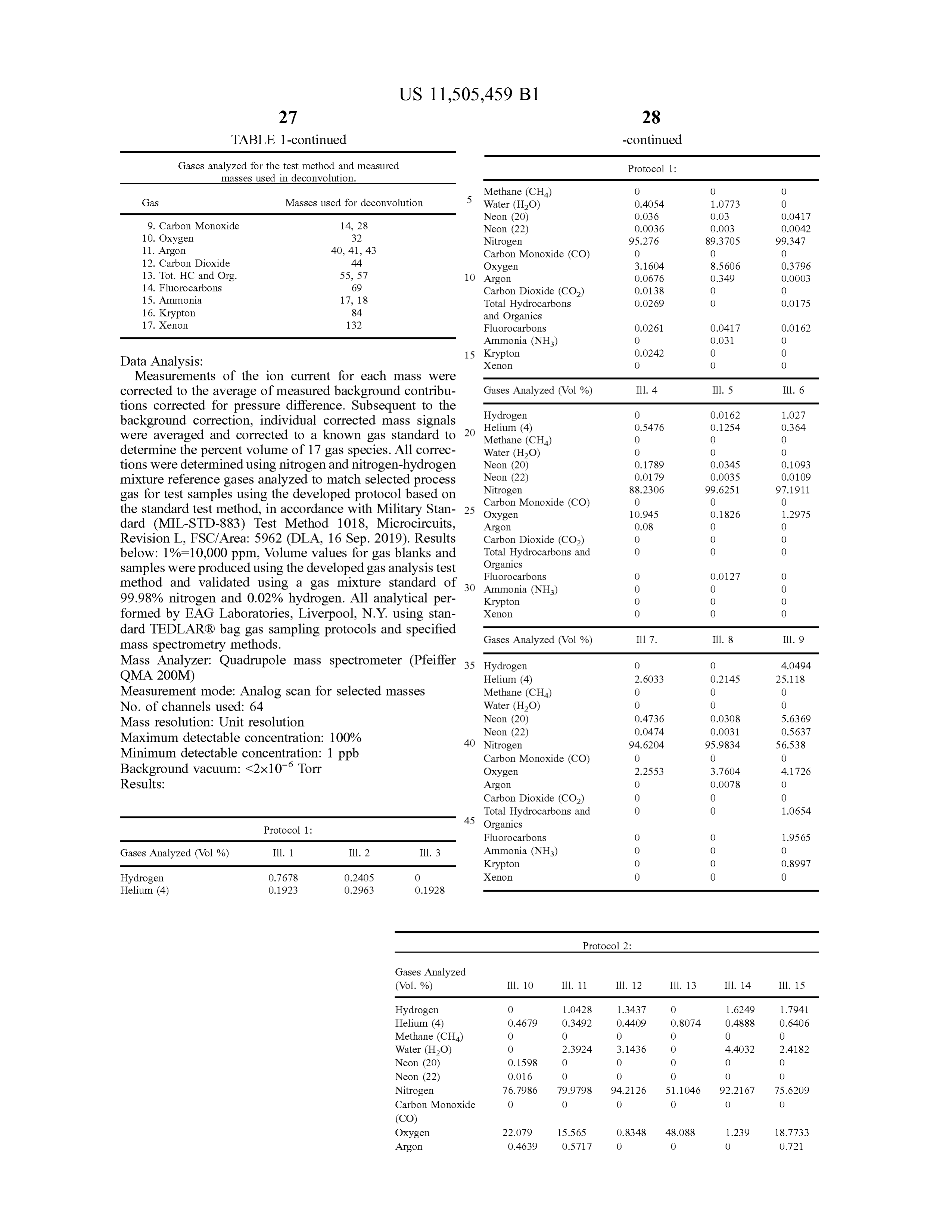
Page 37
Protocol 2 :
Gases Analyzed ( Vol. % ) Ill . 10 Ill . 11 Ill. 12 Ill . 13 Ill . 14 Ill . 15
Carbon Dioxide 0 0.0991 0.0244 0 0.0274 0.0319
Total Hydrocarbons 0 0 0 0 0 0 and Organics
Fluorocarbons 0.0147 0 0
Ammonia (NH3)
Krypton
Xenon
Standard (Nitrogen ): ( c ) directing the feed gas from step ( b ) to a reactor assembly comprising:
a gas inlet and one or more gas outlets;
Vol %
Standard a reactor chamber containing a nanoporous carbon 99.98 vol % N 20 disposed within a cup and , optionally, covered with
Gases Analyzed 200 ppm H2 a cap ;
a first porous frit defining a floor of the reactor chamber
Helium (3 ) 0.0000 disposed within the cup , Helium (4 ) 0.0000 a second porous frit defining the ceiling of the reactor Methane (CH4) 0.0000 25 chamber; wherein each porous frit has a porosity that Water (H2O) 0.0000 is sufficient to allow a gas to permeate into the
reactor chamber;
Nitrogen 99.9777 a reactor head space disposed above the reactor cham Carbon Monoxide ( CO )
Oxygen
ber;
Argon 0.0000 30 at least one reactor assembly (RA ) coil surrounding the Carbon Dioxide ( CO2 ) 0.0000 reactor chamber and /or reactor head space operably Total Hydrocarbons and Organics 0.0000 connected to a power supply, wherein a computer Fluorocarbons 0.0000 processing unit is configured to control the power Ammonia (NH3)
Krypton
supply to the RA coil ;
35 ( d) subjecting the nanoporous carbon to harmonic pat terning to instantiate hydrogen ;
( f) collecting a product gas comprising the hydrogen; and
The patent and scientific literature referred to herein ( g ) isolating the hydrogen from the product gas . establishes the knowledge that is available to those with skill 2. The process of claim 1 , wherein the cup is composed in the art . All United States patents and published or 40 of graphite.
unpublished United States patent applications cited herein 3. The process of claim 1 , wherein the cap is composed of are incorporated by reference. All published foreign patents graphite, platinum , palladium or ruthenium .
and patent applications cited herein are hereby incorporated 4. The process of claim 1 , further comprising a pole by reference. All other published references, documents, disposed below the reactor chamber and above the gas inlet. manuscripts and scientific literature cited herein are hereby 45 5. The process of claim 4 , wherein the pole is composed incorporated by reference . of quartz .
While this invention has been particularly shown and 6. The process of claim 1 , wherein : the feed gas comprises described with references to preferred embodiments thereof, nitrogen .
it will be understood by those skilled in the art that various 7. The process of claim 1 , wherein the nanoporous carbon changes in form and details may be made therein without 50 comprises graphene having at least 95 % wt . carbon (metals departing from the scope of the invention encompassed by basis ) having a mass mean diameter between 1 um and 5 the appended claims . Numerical values where presented in mm , and an ultramicropore surface area between about 100 the specification and claims are understood to be approxi- and 3000 m²/ g .
mate values ( e.g. , approximately or about) as would be 8. The process of claim 1 , wherein the nanoporous carbon determined by the person of ordinary skill in the art in the 55 has been degassed.
context of the value . For example, a stated value can be 9. The process of claim 1 , wherein the RA coil is an understood to mean within 10 % of the stated value , unless induction coil .
the person of ordinary skill in the art would understand 10. The process of claim 1 , wherein the electromagnetic otherwise, such as a value that must be an integer. embedding enclosure ( E/MEE ) comprises at least 5 E/MEE 60 pencil lamps located along a gas line containing the feed gas ;
What is claimed is : wherein each E /MEE pencil lamp is independently placed 1. A process for producing hydrogen comprising the steps such that its longitudinal axis is ( i ) parallel to an of: internal gas line , (ii ) disposed radially in a vertical (a ) adding a feed gas to an electromagnetic embedding plane to the internal gas line , or (iii ) perpendicular to enclosure (E/MEE) ; 65 the plane created along the longitudinal axis of the (b ) exposing the feed gas to at least one E/MEE light internal gas line or along the vertical axis of the internal source ; gas line; and
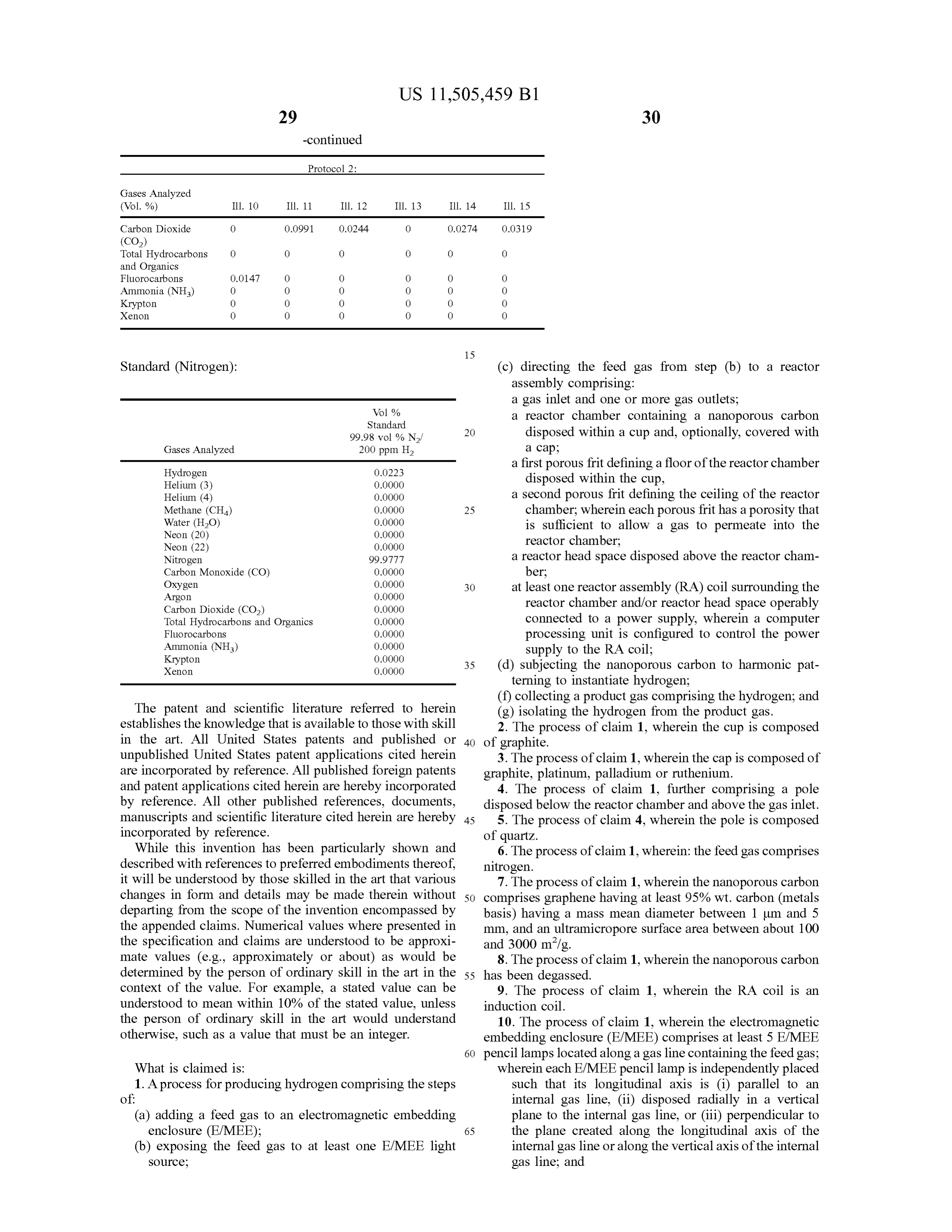
Page 38
wherein each E/ MEE pencil lamp is independently affixed at least one E/ MEE pencil lamp positioned above the to one or more pivots that permit rotation between gas line and at least one E/MEE pencil lamp posi about 0 and 360 degrees with respect to the x , y , and / or tioned to the side of the gas line ; z axis wherein (i ) the x - axis is defined as the axis wherein each E /MEE pencil lamp is independently parallel to the gas line and its vertical plane , ( ii ) the 5 rotatably mounted , located along the length of the y -axis defining the axis perpendicular to the gas line gas line;
and parallel to its horizontal plane, and (iii ) the z - axis a power supply operably connected to each E/MEE is defined as the axis perpendicular to the gas line and pencil lamp;
parallel to its vertical plane. a computer processing unit configured to independently 11. The process of claim 1 , wherein the feed gas com- 10 control powering each E/MEE pencil lamp and a prises at least 99 % nitrogen. rotation position of each E/MEE pencil lamp; 12. The process of claim 1 , wherein the feed gas com (b ) powering each E/MEE pencil lamp, thereby subjecting prises at least about 99.9 % nitrogen . the feed gas to electromagnetic radiation ; optionally 13. The process of claim 12 , wherein the product gas rotating each E /MEE pencil lamp; comprises at least about 1 % vol . hydrogen. 15 ( c ) directing the feed gas from step ( b ) to a reactor 14. The process of claim 13 , wherein the product gas assembly comprising:
further comprises helium , argon , neon and combinations a gas inlet and one or more gas outlets; thereof.
15. The process of claim 13 , wherein the helium , argon , a reactor chamber containing a nanoporous carbon neon and combinations thereof comprise at least 1 % vol . of 20 disposed within a cup and , optionally, covered with the product gas . a cap ;
16. The process of claim 13 , wherein the product gas a first porous frit defining a floor of the reactor chamber contains less than about 0.5 vol % CO2., such as less than 100 disposed within the cup , ppm CO2 a second porous frit defining the ceiling of the reactor 17. A product gas produced by a process of claim 1 . 25 chamber and disposed below the cap ; wherein each 18. A product gas of claim 17 , comprising at least 1 % vol .
porous frit has a porosity that is sufficient to allow a hydrogen, nitrogen , and one or more gases selected from the gas to permeate into the reactor chamber and contain group consisting of helium , argon , and neon . a nanoporous carbon ;
19. The product gas of claim 17 , comprising at least 4 % a reactor head space disposed above the reactor cap ; vol . hydrogen, nitrogen, and one or more gases selected 30 at least one reactor assembly (RA ) coil surrounding the from the group consisting of helium , argon , and neon . reactor chamber and /or reactor head space operably 20. The product gas of claim 19 , wherein the product gas connected to the power supply, wherein the com contains less than about 0.5 vol % CO2 , such as less than 100 puter processing unit is configured to control the ppm CO2 power supply to the RA coil ; 21. A process for producing hydrogen comprising the 35 ( d) powering each RA coil to a first electromagnetic steps of: energy level ;
( a ) adding a feed gas to an electromagnetic embedding ( e) subjecting the nanoporous carbon to harmonic pat enclosure ( E /MEE ) comprising: terning to instantiate hydrogen; and a gas line containing the feed gas ; at least one E/MEE ( f) collecting a product gas comprising hydrogen. pencil lamp positioned below the gas line , * *
Provenance
- Collection
- Patents citing this work
- Original assignee
- Alpha Portfolio LLC
- Pages
- 38
- Method
- pdftotext (the PDF's own text layer) + pdftoppm 300dpi page scans
- Patent office record
- patents.google.com →
- Source
- Google Patents citing-documents table
- Inventors
- Christopher J. Nagel; Stephen P. Lemoi; Mark G. Janson; Alpha Portfolio LLC
- Published
- 2022-11-22
- Transcribed from
- patentimages.storage.googleapis.com →