patent · US11186915B2
Electrolysis system and method for a high electrical energy transformation rate
30 November 2021
Page 1 — bibliographic record
( 12 ) United States Patent
Garcés Barón
(54) ELECTROLYSIS SYSTEM AND METHOD ( 56 ) References Cited
FOR A HIGH ELECTRICAL ENERGY
TRANSFORMATION RATE U.S. PATENT DOCUMENTS
( 71 ) Applicant: Jorge Garcés Barón , Las Condes ( CL ) 4,936,961 A 6/1990 Meyer
(72) Inventor : Jorge Garcés Barón , Las Condes ( CL ) (Continued ) ( * ) Notice : Subject to any disclaimer, the term of this FOREIGN PATENT DOCUMENTS patent is extended or adjusted under 35 DE 10 2011 002 104 Al 10/2012
( 21 ) Appl . No .: 16 / 326,001 OTHER PUBLICATIONS International Search Report and Written Opinion dated Dec. 22 , ( 22 ) PCT Filed : Aug. 11 , 2017 2017 for International Application No. PCT /CL2017 /050040 , filed
$ 371 ( c ) ( 1 ). Primary Examiner Ciel P Contreras ( 2 ) Date : Feb. 15 , 2019 (74 ) Attorney, Agent, or Firm — Mintz Levin Cohn Ferris Glovsky and Popeo , P.C.
( 87 ) PCT Pub . No .: WO2018 /032120 ( 57 ) ABSTRACT PCT Pub . Date : Feb. 22 , 2018 The invention relates to an electrolysis system to conduct ( 65 ) Prior Publication Data oxidation and reduction reactions, comprising one or more electrolytic cells , with each one of them being formed by at
US 2020/0141013 A1 May 7 , 2020 least a pair of electrodes and an electrolyte provided between said electrodes, wherein the assembly of said one or more electrolytic cells defines an electrolyzer; and an energy
Related U.S. Application Data source that supplies an electrical signal to the electrolyzer; ( 60 ) Provisional application No. 62 / 375,200 , filed on Aug. wherein said electrolytic cell is built in the form of a 15 , 2016 . capacitor of cylindrical plates, wherein said cylindrical plates are defined by the electrodes of the electrolytic cell (51 ) Int. Ci. formed by tubes arranged in a substantially concentric way C25B 1/04 ( 2021.01) within each other, thus defining a central electrode, an outer C25B 15/02 ( 2021.01 ) electrode and a space between electrodes, wherein the central electrode corresponds to the anode of the capacitor, ( Continued ) the outer electrode to the cathode of the capacitor and the ( 52 ) U.S. CI . electrolyte to the dielectric means of the capacitor ; wherein CPC C25B 1/04 ( 2013.01 ) ; C25B 9/70 the electrical signal received by the electrolytic cell or cells (2021.01 ) ; C25B 11/00 (2013.01 ) ; C25B 15/02 that form the electrolyzer correspond to a direct current (2013.01 ) pulse, wherein said pulse is configured for each electrolyz (58) Field of Classification Search er's electrolytic cell to operate : In a charge transient regime CPC C25B 1/04 ; C25B 1/042 ; C25B 1/044 ; of each cell during the current pulse ; and In a discharge C25B 9/70 ; C25B 15/02 transient regime of each cell during the time between current
See application file for complete search history . (Continued ) V cell (t)
Veel cell ( DT)
Voll cell ( T)
Page 2
pulses ; wherein said charge and discharge transient regimes are defined by the construction of each electrolytic cell in the form of a cylindrical plates capacitor. In addition , the invention also relates to associated method and uses . 19 Claims , 8 Drawing Sheets
Page 3
Drawing sheet — no readable text.
Page 4
Drawing sheet — no readable text.
Page 5
Drawing sheet — no readable text.
Page 6
Drawing sheet — no readable text.
Page 7
Drawing sheet — no readable text.
Page 8
Drawing sheet — no readable text.
Page 9
Drawing sheet — no readable text.
Page 10
Drawing sheet — no readable text.
Page 11
ELECTROLYSIS SYSTEM AND METHOD hydrogen and oxygen atoms as elemental gases and facili FOR A HIGH ELECTRICAL ENERGY tating the reduction - oxidation reaction . Then , the solution of TRANSFORMATION RATE the U.S. Pat . No. 4,936,961 does not propose the control of operation parameters to maximize the electrical efficiency;
CROSS - REFERENCE TO RELATED 5 therefore , it does not take advantage of the electrolytic cell APPLICATIONS design to reduce the energy consumption in generating hydrogen and oxygen . Additionally, the technology of docu
This application is a national stage entry , filed under 35 ment U.S. Pat. No. 4,936,961 operates the electrolytic cell U.S.C. § 371 , of International Application No. PCT/ mainly under an approach of steady state not taking advan CL2017 /050040 , filed on Aug. 11 , 2017 , which claims 10 tage of the transient condition characteristics thereof. priority to U.S. Provisional Patent Application No. 62/375 , By focusing the invention in the generation of hydrogen 200 filed Aug. 15 , 2016 , and incorporates their disclosures and oxygen, one of the most relevant uses of the current herein by reference in their entireties . electrolysis methods and systems is to identify the following The present invention is related to an improved electroly- processes for the generation of hydrogen and oxygen sis method and system , wherein a controlled supply of 15 through electrolysis:
pulsating current is implemented and an electrolytic cell Alkaline electrolysis design is provided to optimize the capacitive and inductive Electrolysis by polymer electrolyte membrane ( PEM ) behavior of the cell . The method and system of the present Electrolysis at high temperatures or at vapor step invention allow adjusting the best amplitude and ratio of the In the electrolytic reaction , the efficiency of the hydrogen application period of the current pulse to maximize the 20 produced at the present conditions is about 4.9-5.6 kWh per electrical efficiency of the electrochemical process in theeach mº of hydrogen produced , i.e. almost 50% to 60 % of electrolytic cell , wherein production of said cell is mainenergy efficiency ( considering a lower heat value or LHV of tained under a transient regime making use of the resonant H2 ) , which can be more expensive than the hydrogen characteristics of the circuit . obtained from fossil fuels. Additionally, the hydrogen pro 25 duced in the cathode must be purified , since it may contain
BACKGROUND OF THE INVENTION oxygen impurities and certain amount of moisture. The hydrogen stream is dried through an adsorbent and the
In the state of the art there are several solutions related to oxygen impurities are removed with a DeOxo converter. The electrolysis systems and methods, which implement a pul- alkaline process, however, is one of the simplest and eco sating signal as a supply current, by associating such sys- 30 nomic processes for the production of hydrogen. tems and methods to a special electrode design . For In addition, although the electrolysis process by PEM has example, the U.S. Pat . No. 3,954,592 teaches an electrolytic nowadays better yields than alkaline electrolysis, one of the cell improving the efficiency by supplying a pulsed DC advantages of an alkaline electrolyzer over PEM is the fact current to the electrodes thereof. Said document suggests a of allowing the stability of electrode materials, such as generally cylindrical anode with a fluted outer surface 35 nickel or stainless steel ; thus, allowing a structure of much surrounded by a segmented cathode having an active area lower cost that does not require expensive materials . Fur equal to the active area of the anode . The pulsing of the thermore, the use of PEM procedure has the disadvantage current is carried out at a rate of between 5,000 and 40,000 that the exchange membranes are highly sensitive to impu pulses per minute. According to said document, in such an rities and also have a limited shelf life time . arrangement the current level may be about 220 amps and 40 Finally, in relation to the process of electrolysis at high the electrode voltage may be about 3 volts . Nevertheless, the temperatures or at vapor step , it should be noted that its main U.S. Pat. No. 3,954,592 suggests working with a current advantage lies on the efficiency higher than ordinary elec pulse that cannot be adjusted to maximize the electrical trolyzers, and its main disadvantage is the availability of an efficiency or to take advantage of the design aspects of the installation of industrial plant for processing high operating electrolytic cell , thus resulting in an unnecessary energy 45 temperatures, and the delivery of an important energy supply consumption and the unfeasibility of implementing this for the high temperature of the process.
solution to a competitive industrial scale . Additionally, the Then, the common problem that these electrolysis tech technology of the U.S. Pat. No. 3,954,592 operates the nologies side today is the low energy efficiency in the electrolytic cell focusing on its steady state without taking conversion of an energy source for the production of H , as advantage of the transient states thereof. 50 an energy carrier. Accordingly, up to now a common objec On the other hand , the U.S. Pat . No. 4,936,961 defines a tive for all these electrolysis systems and methods has been method for the production of aa fuel gas , which comprises a the effort of reducing voltage surges in order to be more mixture of hydrogen and oxygen obtained from water as a energy efficient in the light of the energy transfer, thus dielectric medium in an electrical resonant circuit . Although reducing production costs .
said document discloses a method that takes advantages of 55 For that reason , the current efforts to improve the elec the resonant features of the circuit, thus implementing a trolysis cells , apparatuses, systems and methods, mainly for pulsating current, the method in said solution obtains a producing hydrogen , focus on the implementation of elec mixture of hydrogen and oxygen from the breakdown of a trolytes and components of low resistivity or resistance , water molecule by vibration of the medium generated by which reduces the voltage used to achieve higher electrical electromagnetic fields; this makes the solution a complex 60 currents ( Ohm's Law ) . In this sense , the electrolysis models one . Furthermore , said documents suggests a capacitive are based on a mainly resistive modeling of the electrolytic design using water as the dielectric medium , including an cell , where the main objective is addressed to reduce the inductance connected in series with a capacitor or capacitor. resistance of the medium ( electrolyte ) to optimize the pro This design allows that the water molecule be subjected to cess from the point of view of efficiency in energy transfer. an electric field between the capacitor plates , thus inducing 65 In this kind of modeling , applying large voltage surges to the a resonance within the water molecule , whereby the bond process is usual , and this potential only has been reduced by between the molecule atoms is broken , thus liberating the considerably decreasing the electrolyte resistance .
Page 12
Therefore, there is a need for improved electrolysis the present invention considers the fact of maximizing the method and system to maximize the electrical efficiency of capacitive behavior of the cell and modeling the same as a the electrolysis process by adjusting the operating param- real capacitor, i.e. , including capacitive , resistive and induc eters according to the design of the electrolytic cell that is tive elements as part of the electrolytic cell and focusing the potentiated in a production model under a transient regime . 5 operation thereof on the charging and discharging transient Furthermore, in the production of hydrogen and oxygen , it regimes of the cell acting as capacitor. is necessary to have a method and apparatus capable of In this regard, the present invention considers the pro generating such gases separately and at low energy cost , thus duction of the electrolytic cell under its transient regime , i.e. , maximizing the use of electrical energy . 10 taking advantage of the transition periods in the electrical behavior of the cell given by its modeling , which is mainly
DESCRIPTION OF THE INVENTION capacitive and inductive. Under its temporary or transient regime, the electrolytic cell behaves according to the evo
An objective of the present invention is providing an lution of the voltage and current in a capacitor, establishing electrolysis method and system , which maximize the energy 15 an electrochemical production in said transient regime. efficiency of the electrolysis process , optimizing the opera- According to a preferred embodiment of the present inven tion of the electrolytic cell , which is reflected in maximizing tion , the cell completely operates under transient regime, the electrical efficiency of the production process according applying a differential modeling of Faraday's law to repli the following equation : cate the electrochemical production under said regime . The 20 differential modeling of the unified Faraday's law states that the mass obtained in the production process is a function of
Electricalefficiency = Energy of the generated product
Consumed electric power [ % ] time , according to the following equation :
In the case of water electrolysis, the energy of the gen- 25 d Obtained Mass = K * i(t) * dt, with K = H2 Chemical Equivalent erated product can be consider as the Lower Heating Value Faraday's Constant ( LHV) of H2 , which value if 120 [MJ/kg ].
Another objective of the present invention is to provide an Then, if the mass obtained in aa T period of the pulse wave electrolysis method and system , in which the operating is calculated , it is obtained as follows: parameters of power supply are adjusted , taking advantage 30 of design aspects of the electrolytic cell by modeling the process, which is not a traditional resistive approach prin cipally . Mass Obtained - 1 K * i( t )dt, with K = H2Faraday's
Constant
Another objective of the present invention is to provide an electrolysis method and system that implement an electro- 35 lytic cell design , which maximizes the capacitive , inductive Wherein i (t) represents the current density variable in and resistive features of the cell , defining the operating time . This approach is similar to the one of use in direct parameters, maximum amplitude, frequency and pulse width current, where the constant character of the current applied of electric power, so as to maximize the electrical efficiency to the system leaves the equation in its original form with of the production process in the electrolysis cell . 40
Another objective of the present invention is to provide a Mass Obtained 0- > T = K * I * T . Accordingly , the capacitive features of the electrolytic method and system for hydrogen and oxygen generation by cell provide an alkaline electrolysis, optimizing the operating parameters descending times inertial of the behavior during ascending and capacitor's charge, where only the and taking advantage of the design of the electrolytic cell to resistive and capacitive effects of model can be seen , which maximize the electrical efficiency. 45
In order to achieve the preceding objectives, the solution can be reproduced by the equations associated to capacitors of the present invention comprises a method and a system and the charge behavior thereof. For instance , the capacitive with a special electrolysis apparatus or electrolyzer fed by a behavior of the electrolytic cell allows taking advantage of voltage source with pulsating current, which commonly the current peaks that take place at each initial capacitor causes decomposition of the electrolyte using electricity. In 50 charge; thus the effective resistance of the cell is substan short, electrolysis is an electrochemical separation process tially reduced during said peaks. Additionally, the electro by oxidation - reduction , which takes place when passing lytic cell has a resonant behavior with its own natural electric power through a molten electrolyte or an aqueous resonance frequencies given by their construction and induc solution existing between the electrodes of an electrolytic tive behavior, which is combined with the inertia constants cell . 55 provided by the capacitive design . In this context, with the aim of maximizing the production Then, the invention is based on and electric and construc of the electrolytic process the electrical current circulating tive architecture , which highlights capacitance and induc through the cell should be maximized , which should be tance parameters and conditions provided by the resonant accompanied by the application of aa low voltage to mini- and capacitive models of the cell , thus providing a design mize the energy consumption. The present invention models 60 that does not favor the coexistence of gas produced and the electrolytic cell capacitively, i.e. , like a capacitor, where electrolyte on the surfaces of gas production, such as stacks the electrolyte in the cell is considered as the dielectric or standard dry heap of the industry, but favoring the medium of the capacitor. This kind of modeling of an extraction of the gases produced by geometry, and imple electrolytic cell is already known and the most common menting current pulses with over -damping transient that form thereof consists in defining that the cell is composed of 65 favor the release of bubbles from the cell plates . Further two parallel electrodes plates located at some distance from more, dosing of the energy injected into the cell in resonance each other and separated by the electrolyte . Nevertheless, condition is implemented, where periods of energy applica
Page 13
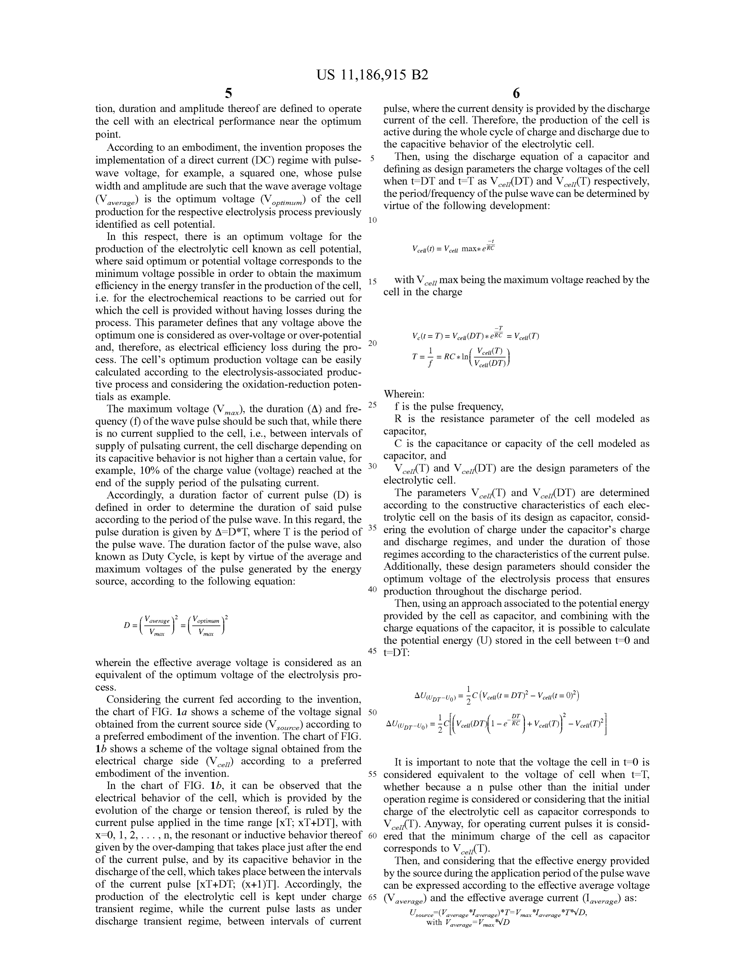
tion, duration and amplitude thereof are defined to operate pulse , where the current density is provided by the discharge the cell with an electrical performance near the optimum current of the cell . Therefore , the production of the cell is point . active during the whole cycle of charge and discharge due to According to an embodiment, the invention proposes the the capacitive behavior of the electrolytic cell . Then, using the discharge equation of a capacitor and implementation of aa direct current ( DC ) regime with pulse 5 defining wave voltage , for example , a squared one , whose pulse as design parameters the charge voltages of the cell width and amplitude are such that the wave average voltage when t= DT and t=T as V cel (DT) and V ceai ( T) respectively, (Vaverage) is the optimum voltage (Voptimum ) of the cell the period / frequency of the pulse wave can be determined by production for the respective electrolysis process previously 10 virtue of the following development: identified as cell potential.
In this respect , there is an optimum voltage for the production of the electrolytic cell known as cell potential, Vcel (t) = V cell max * e RC where said optimum or potential voltage corresponds to the minimum voltage possible in order to obtain the maximum 15 with V cell max being the maximum voltage reached by the efficiency in the energy transfer in the production of the cell , cell in the charge i.e. for the electrochemical reactions to be carried out for which the cell is provided without having losses during the process. This parameter defines that any voltage above the -T optimum one is considered as over-voltage or over - potential 20 and , therefore, as electrical efficiency loss during the pro
Vext
er == Vell
cess . The cell’s optimum production voltage can be easily calculated according to the electrolysis -associated produc
tive process and considering the oxidation - reduction poten Wherein :
tials as example.
The maximum voltage ( Vmax ), the duration ( A ) and fre 25 f is the pulse frequency, quency ( f) of the wave pulse should be such that, while there R is the resistance parameter of the cell modeled as is no current supplied to the cell , i.e. , between intervals of capacitor, supply of pulsating current, the cell discharge depending on C is the capacitance or capacity of the cell modeled as its capacitive behavior is not higher than a certain value , for 30 capacitor, and example , 10 % of the charge value ( voltage ) reached at the V ceil( T) and V celi(DT) are the design parameters of the end of the supply period of the pulsating current. electrolytic cell .
Accordingly, a duration factor of current pulse ( D ) is The parameters Veeli ( T) and Vcel (DT) are determined defined in order to determine the duration of said pulse according to the constructive characteristics of each elec according to the period of the pulse wave . In this regard , the trolytic cell on the basis of its design as capacitor, consid pulse duration is given by A = D * T, where T is the period of 35 ering the evolution of charge under the capacitor's charge the pulse wave . The duration factor of the pulse wave, also and discharge regimes , and under the duration of those known as Duty Cycle , is kept by virtue of the average and regimes according to the characteristics of the current pulse . maximum voltages of the pulse generated by the energy Additionally, these design parameters should consider the source , according to the following equation : optimum voltage of the electrolysis process that ensures 40 production throughout the discharge period.
Then, using an approach associated to the potential energy optimum provided by the cell as capacitor, and combining with the
max V max charge equations of the capacitor, it is possible to calculate the potential energy (U ) stored in the cell between t=0 and
wherein the effective average voltage is considered as an equivalent of the optimum voltage of the electrolysis pro cess .
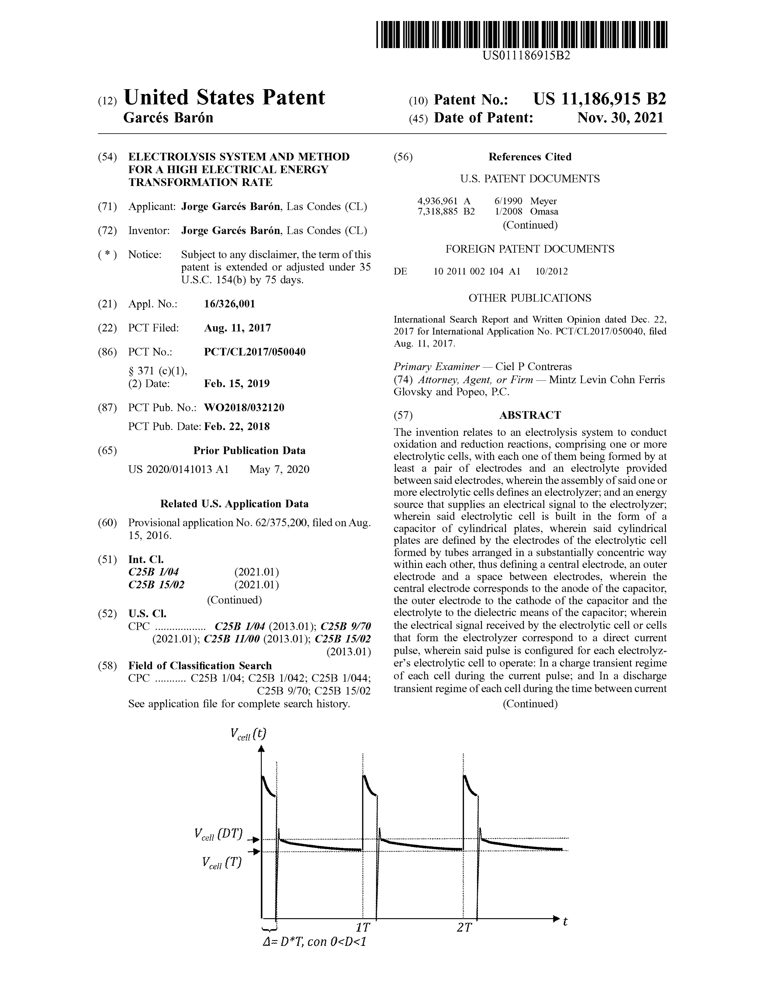
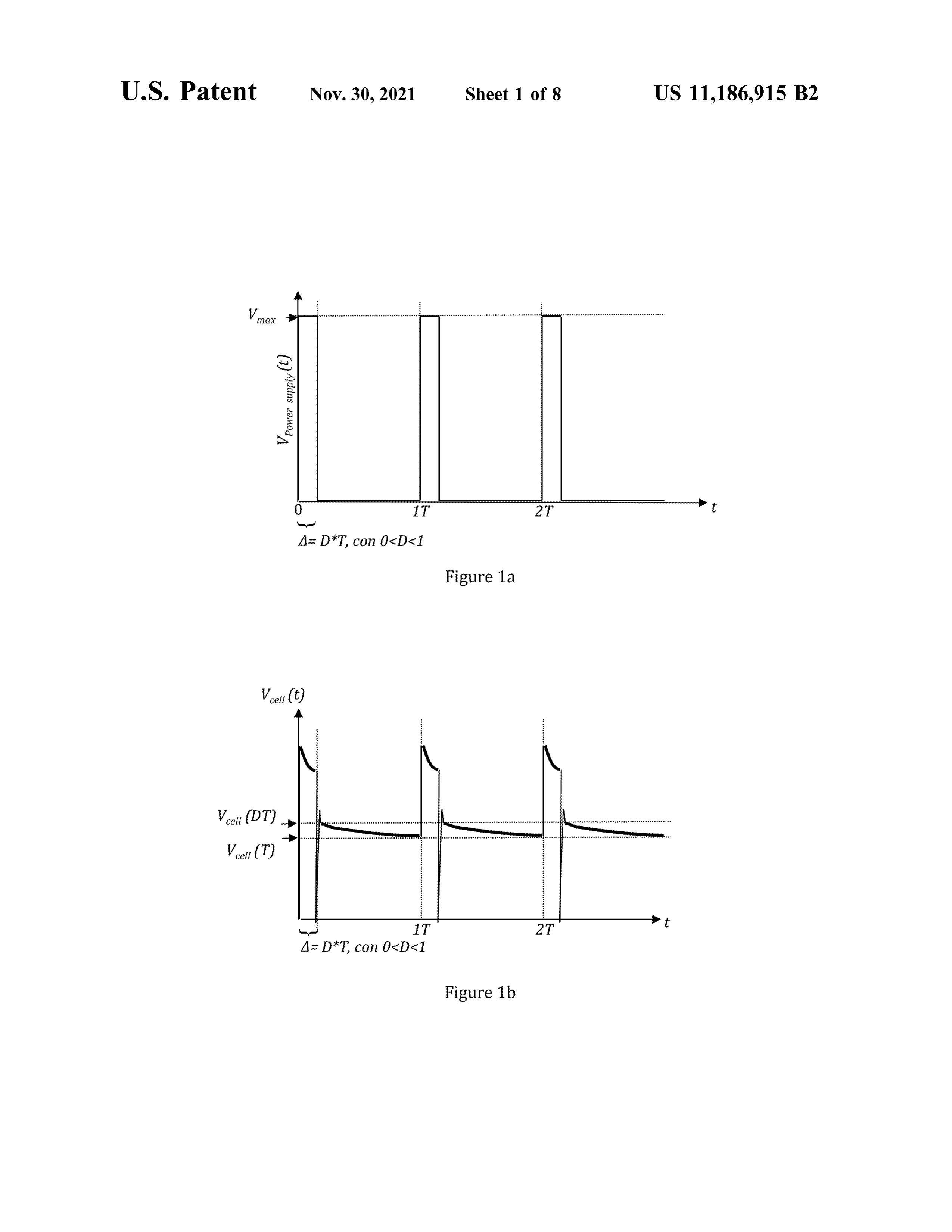
Considering the current fed according to the invention , the chart of FIG . la shows a scheme of the voltage signal 50
obtained from the current source side (V source) according to AU(UDT-00) a preferred embodiment of the invention . The chart of FIG .
d][vcabro(1- ]+vetat) – Veentry
1b shows a scheme of the voltage signal obtained from the electrical charge side (V cell) according to a preferred It is important to note that the voltage the cell in t=0 is embodiment of the invention . 55 considered equivalent to the voltage of cell when t = T, In the chart of FIG . 1b , it can be observed that the whether because a n pulse other than the initial under electrical behavior of the cell , which is provided by the operation regime is considered or considering that the initial evolution of the charge or tension thereof, is ruled by the charge of the electrolytic cell as capacitor corresponds to current pulse applied in the time range [xT ; xT + DT ] , with Vcez ( T ). Anyway, for operating current pulses it is consid X =0 , 1 , 2 , .. n , the resonant or inductive behavior thereof 60 ered that the minimum charge of the cell as capacitor given by the over -damping that takes place just after the end corresponds to V cel ( T ).
of the current pulse , and by its capacitive behavior in the Then, and considering that the effective energy provided discharge of the cell , which takes place between the intervals by the source during the application period of the pulse wave of the current pulse [xT + DT; ( x + 1 ) T ]. Accordingly, the can be expressed according to the effective average voltage production of the electrolytic cell is kept under charge 65 (Vaverage) and the effective average current ( laverage) as : transient regime, while the current pulse lasts as under Usource = (VaVaverage* =laverage)* T = Vmax * Iaverage * T* VD , discharge transient regime, between intervals of current with Vaverage y * D max
Page 14
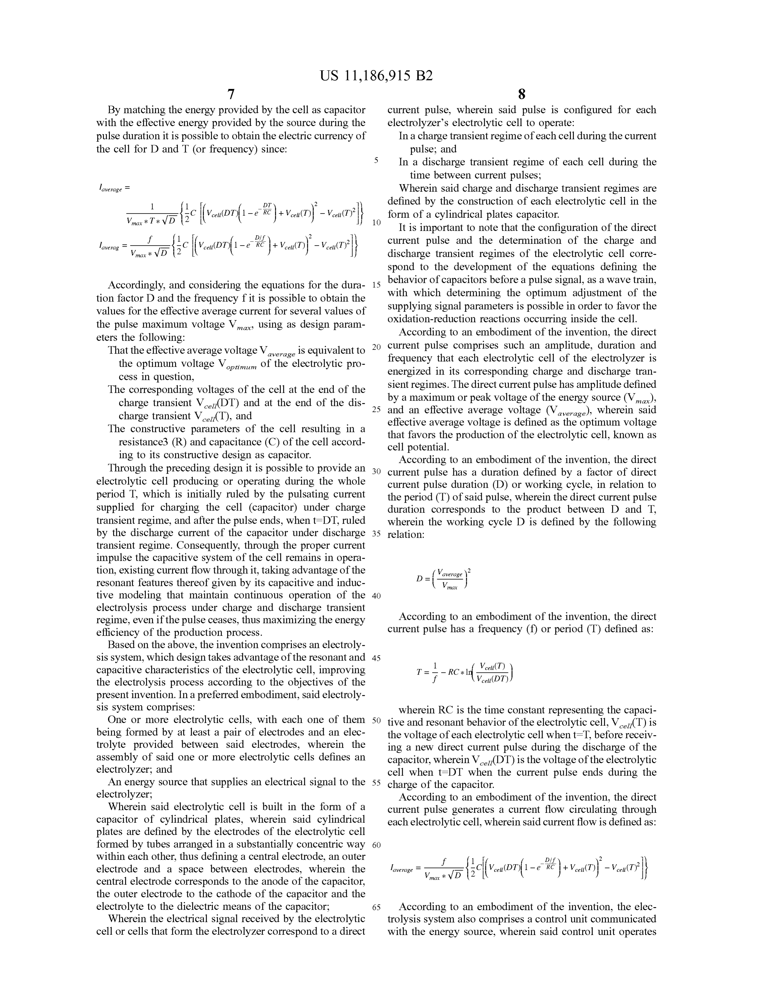
By matching the energy provided by the cell as capacitor current pulse , wherein said pulse is configured for each with the effective energy provided by the source during the electrolyzer's electrolytic cell to operate: pulse duration it is possible to obtain the electric currency of In a charge transient regime of each cell during the current the cell for D and T (or frequency ) since : pulse ; and
In a discharge transient regime of each cell during the time between current pulses ;
laverage
Wherein said charge and discharge transient regimes are defined by the construction of each electrolytic cell in the
??? &{c [[vcrubrif1-e bit )+Vecern) - Vecuty
RC + V cell( ) 10 form of a cylindrical plates capacitor.
It is important to note that the configuration of the direct
Vonnévo{ c|(verado(1-2 mié) + Vonkt) very
Vcell( T Vcell( ) current pulse and the determination of the charge and discharge transient regimes of the electrolytic cell corre spond to the development of the equations defining the
Accordingly, and considering the equations for the dura- 15 with behavior of capacitors which beforethea optimum determining pulse signaladjustment , as a waveoftrainthe, tion factor D and the frequency fit is possible to obtain the supplying signal parameters is possible in order to favor the values for the effective average current for several values of the pulse maximum voltage V, using as design param oxidation
- reduction reactions occurring inside the cell .
According to an embodiment of the invention, the direct eters the following :
That the effective average voltage V average is equivalent to 20 current pulse comprises such an amplitude, duration and the optimum voltage Voptimum of the electrolytic pro frequency that each electrolytic cell of the electrolyzer is energized in its corresponding charge and discharge tran cess in question , sient regimes . The direct current ilse has amplitude defined The corresponding voltages of the cell at the end of the by charge transient V ceu (DT) and at the end of the dis 25 anda maximum an effective or peak voltage of the energy source ( Vmax. ), average voltage (Vaverage ), wherein said charge transient V cel ( T ), and
The constructive parameters of the cell resulting in a that favors the productionisofdefined effective average voltage the as the optimum voltage electrolytic cell , known as resistance3 (R) and capacitance ( C ) of the cell accord cell potential.
ing to its constructive design as capacitor. According to an embodiment of the invention , the direct Through the preceding design it is possible to provide electrolytic cell producing or operating during the whole current pulsean 30 current pulse has a duration defined by a factor of direct period T , which is initially ruled by the pulsating current the period (T ) duration (D ) or working cycle , in relation to of said pulse , wherein the direct current pulse supplied for charging the cell ( capacitor) under charge duration corresponds to the product between D and T, transient regime , and after the pulse ends, when t = DT, ruled wherein the working cycle D is defined by the following by the discharge current of the capacitor under discharge 35 relation:
transient regime. Consequently, through the proper current impulse the capacitive system of the cell remains in opera tion, existing current flow through it , taking advantage of the = Vaverage resonant features thereof given by its capacitive and induc V.max tive modeling that maintain continuous operation of the 40 electrolysis process under charge and discharge transient regime, even if the pulse ceases , thus maximizing the energy According to an embodiment of the invention , the direct efficiency of the production process . current pulse has a frequency ( f) or period (T ) defined as : Based on the above , the invention comprises an electroly sis system , which design takes advantage of the resonant and 45 1 Vcell ( T ) capacitive characteristics of the electrolytic cell , improving the electrolysis process according to the objectives of the present invention . In a preferred embodiment, said electroly
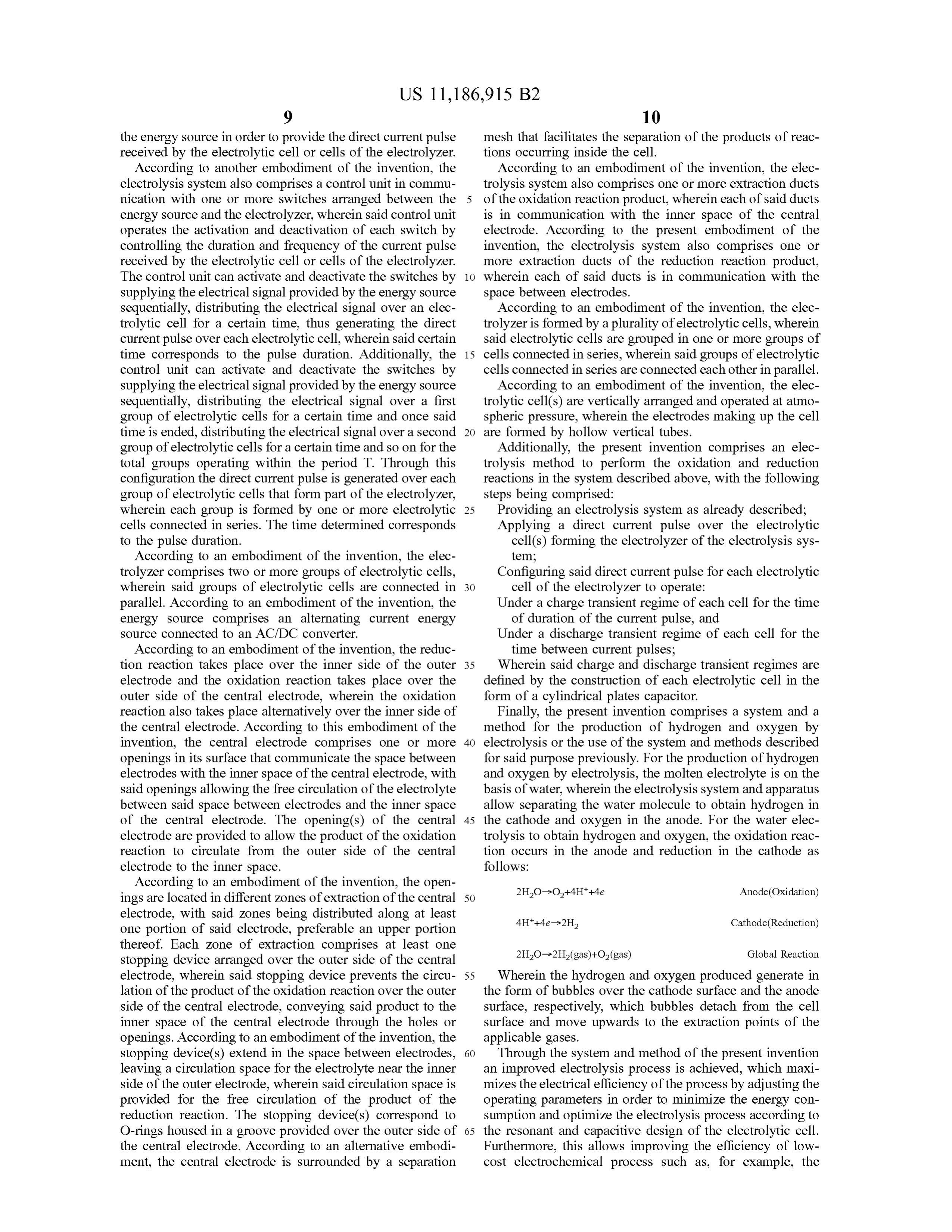
sis system comprises: wherein RC is the time constant representing the capaci One or more electrolytic cells , with each one of them 50 tive and resonant behavior of the electrolytic cell , V celi( T ) is being formed by at least a pair of electrodes and an elec- the voltage of each electrolytic cell when t = T, before receiv trolyte provided between said electrodes, wherein the ing a new direct current pulse during the discharge of the assembly of said one or more electrolytic cells defines an capacitor, wherein V celi (DT) is the voltage of the electrolytic electrolyzer; and cell when t =DT when the current pulse ends during the An energy source that supplies an electrical signal to the 55 charge of the capacitor.
electrolyzer;
Wherein said electrolytic cell is built in the form of a According to an embodiment of the invention , the direct current pulse generates a current flow circulating through capacitor of cylindrical plates , wherein said cylindrical each electrolytic cell , wherein said current flow is defined as : plates are defined by the electrodes of the electrolytic cell formed by tubes arranged in aa substantially concentric way 60 within each other, thus defining a central electrode, an outer electrode and a space between electrodes, wherein the laverage = ) d* ukt)) - veliVcell(7) ] central electrode corresponds to the anode of the capacitor, lepenge = mar* vol{. [[vcxDT (1-2 % )+Veceukt
the outer electrode to the cathode of the capacitor and the 65 electrolyte to the dielectric means of the capacitor ; According to an embodiment of the invention , the elec Wherein the electrical signal received by the electrolytic trolysis system also comprises a control unit communicated cell or cells that form the electrolyzer correspond to a direct with the energy source, wherein said control unit operates
Page 15
the energy source in order to provide the direct current pulse mesh that facilitates the separation of the products of reac received by the electrolytic cell or cells of the electrolyzer. tions occurring inside the cell .
According to another embodiment of the invention, the According to an embodiment of the invention , the elec electrolysis system also comprises a control unit in commu- trolysis system also comprises one or more extraction ducts nication with one or more switches arranged between the 5 of the oxidation reaction product, wherein each of said ducts energy source and the electrolyzer, wherein said control unit is in communication with the inner space of the central operates the activation and deactivation of each switch by electrode . According to the present embodiment of the controlling the duration and frequency of the current pulse invention , the electrolysis system also comprises one or received by the electrolytic cell or cells of the electrolyzer. more extraction ducts of the reduction reaction product, The control unit can activate and deactivate the switches by 10 wherein each of said ducts is in communication with the supplying the electrical signal provided by the energy source space between electrodes.
sequentially, distributing the electrical signal over an elec- According to an embodiment of the invention , the elec trolytic cell for a certain time , thus generating the direct trolyzer is formed by a plurality of electrolytic cells , wherein current pulse over each electrolytic cell , wherein said certain said electrolytic cells are grouped in one or more groups of time corresponds to the pulse duration . Additionally, the 15 cells connected in series, wherein said groups of electrolytic control unit can activate and deactivate the switches by cells connected in series are connected each other in parallel. supplying the electrical signal provided by the energy source According to an embodiment of the invention , the elec sequentially, distributing the electrical signal over a first trolytic cell ( s ) are vertically arranged and operated at atmo group of electrolytic cells for aa certain time and once said spheric pressure, wherein the electrodes making up the cell time is ended, distributing the electrical signal over a second 20 are formed by hollow vertical tubes . group of electrolytic cells for a certain time and so on for the Additionally, the present invention comprises an elec total groups operating within the period T. Through this trolysis method to perform the oxidation and reduction configuration the direct current pulse is generated over each reactions in the system described above , with the following group of electrolytic cells that form part of the electrolyzer, steps being comprised :
wherein each group is formed by one or more electrolytic 25 Providing an electrolysis system as already described ; cells connected in series. The time determined corresponds Applying a direct current pulse over the electrolytic to the pulse duration . cell ( s ) forming the electrolyzer of the electrolysis sys According to an embodiment of the invention , the elec tem ;
trolyzer comprises two or more groups of electrolytic cells , Configuring said direct current pulse for each electrolytic wherein said groups of electrolytic cells are connected in 30 cell of the electrolyzer to operate : parallel. According to an embodiment of the invention , the Under a charge transient regime of each cell for the time energy source comprises an alternating current energy of duration of the current pulse , and source connected to an AC/DC converter. Under a discharge transient regime of each cell for the According to an embodiment of the invention, the reduc- time between current pulses ;
tion reaction takes place over the inner side of the outer 35 Wherein said charge and discharge transient regimes are electrode and the oxidation reaction takes place over the defined by the construction of each electrolytic cell in the outer side of the central electrode, wherein the oxidation form of a cylindrical plates capacitor. reaction also takes place alternatively over the inner side of Finally, the present invention comprises a system and a the central electrode. According to this embodiment of the method for the production of hydrogen and oxygen by invention, the central electrode comprises one or more 40 electrolysis or the use of the system and methods described openings in its surface that communicate the space between for said purpose previously. For the production of hydrogen electrodes with the inner space of the central electrode, with and oxygen by electrolysis, the molten electrolyte is on the said openings allowing the free circulation of the electrolyte basis of water, wherein the electrolysis system and apparatus between said space between electrodes and the inner space allow separating the water molecule to obtain hydrogen in of the central electrode. The opening ( s) of the central 45 the cathode and oxygen in the anode. For the water elec electrode are provided to allow the product of the oxidation trolysis to obtain hydrogen and oxygen , the oxidation reac reaction to circulate from the outer side of the central tion occurs in the anode and reduction in the cathode as electrode to the inner space . follows:
According to an embodiment of the invention , the open 2H20-02 +4H * +4e Anode (Oxidation ) ings are located in different zones of extraction of the central 50 electrode, with said zones being distributed along at least 4H++4e2H2 Cathode (Reduction ) one portion of said electrode , preferable an upper portion thereof. Each zone of extraction comprises at least one 2H20 ? 2H2 ( gas ) + O2 (gas ) Global Reaction stopping device arranged over the outer side of the central electrode, wherein said stopping device prevents the circu- 55 Wherein the hydrogen and oxygen produced generate in lation of the product of the oxidation reaction over the outerthe form of bubbles over the cathode surface and the anode side of the central electrode, conveying said product to the surface, respectively, which bubbles detach from the cell inner space of the central electrode through the holes or surface and move upwards to the extraction points of the openings. According to an embodiment of the invention, the applicable gases.
stopping device ( s) extend in the space between electrodes , 60 Through the system and method of the present invention leaving a circulation space for the electrolyte near the inner an improved electrolysis process is achieved , which maxi side of the outer electrode , wherein said circulation space is mizes the electrical efficiency of the process by adjusting the provided for the free circulation of the product of the operating parameters in order to minimize the energy con reduction reaction . The stopping device ( s ) correspond to sumption and optimize the electrolysis process according to O - rings housed in a groove provided over the outer side of 65 the resonant and capacitive design of the electrolytic cell . the central electrode. According to an alternative embodi- Furthermore, this allows improving the efficiency of low ment, the central electrode is surrounded by a separation cost electrochemical process such as , for example, the
Page 16
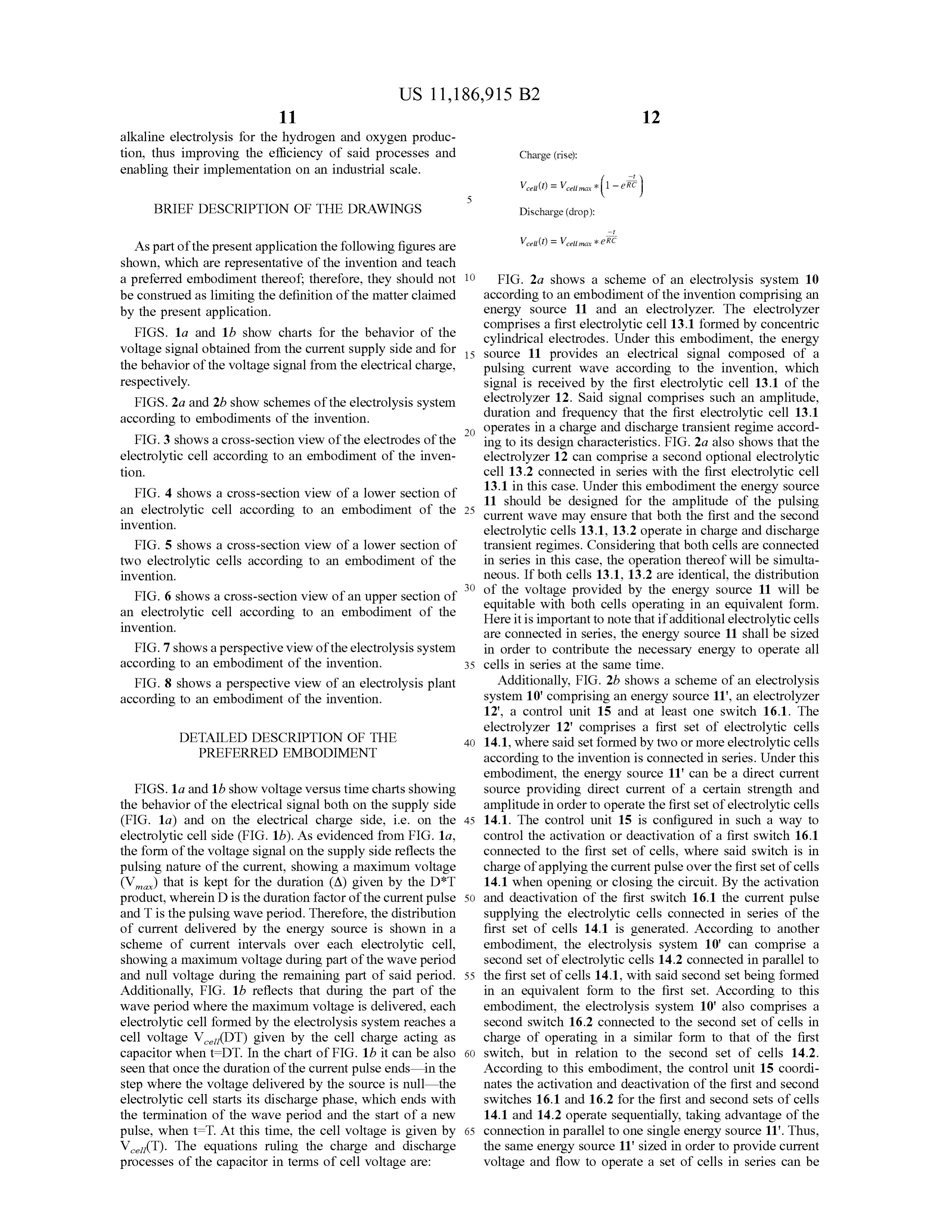
alkaline electrolysis for the hydrogen and oxygen produc tion, thus improving the efficiency of said processes and Charge ( rise):
enabling their implementation on an industrial scale .
BRIEF DESCRIPTION OF THE DRAWINGS
Vcell (t) = V cellmax *
Discharge ( drop ) :
- eRC
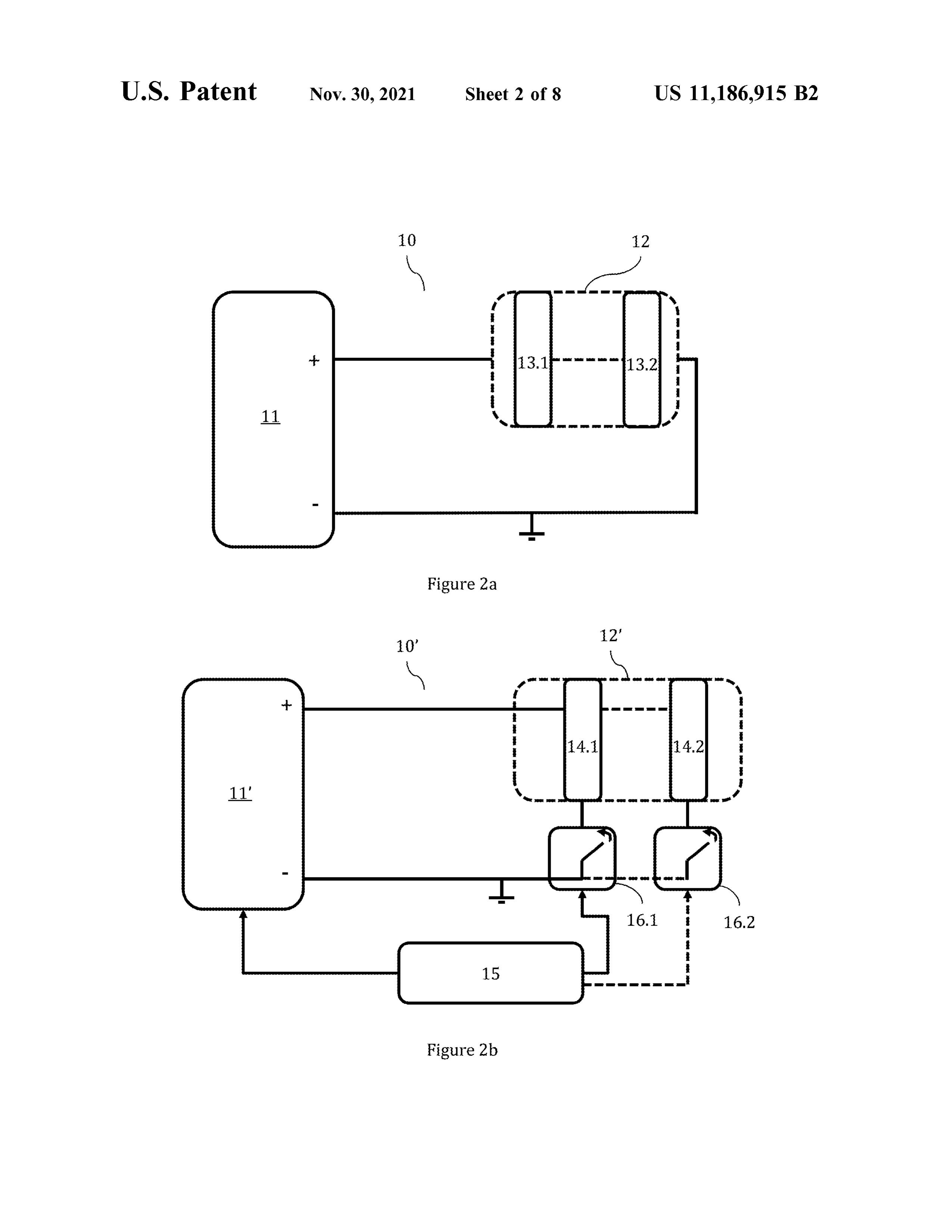
As part of the present application the following figures are Vcell ( t) = V cellmax * { RC shown, which are representative of the invention and teach a preferred embodiment thereof; therefore , they should not 10 FIG . 2a shows a scheme of an electrolysis system 10 be construed as limiting the definition of the matter claimed according to an embodiment of the invention comprising an by the present application . energy source 11 and an electrolyzer. The electrolyzer FIGS . la and 1b show charts for the behavior of the comprises a first electrolytic cell 13.1 formed by concentric voltage signal obtained from the current supply side and for 15 source 11 electrodes cylindrical . Under this embodiment, the energy provides an electrical signal composed of a the behavior of the voltage signal from the electrical charge, pulsing current wave according to the invention , which respectively. signal is received by the first electrolytic cell 13.1 of the FIGS . 2a and 2b show schemes of the electrolysis system electrolyzer duration and 12. Said signal comprises such an amplitude, frequency that the first electrolytic cell 13.1 according to embodiments of the invention .
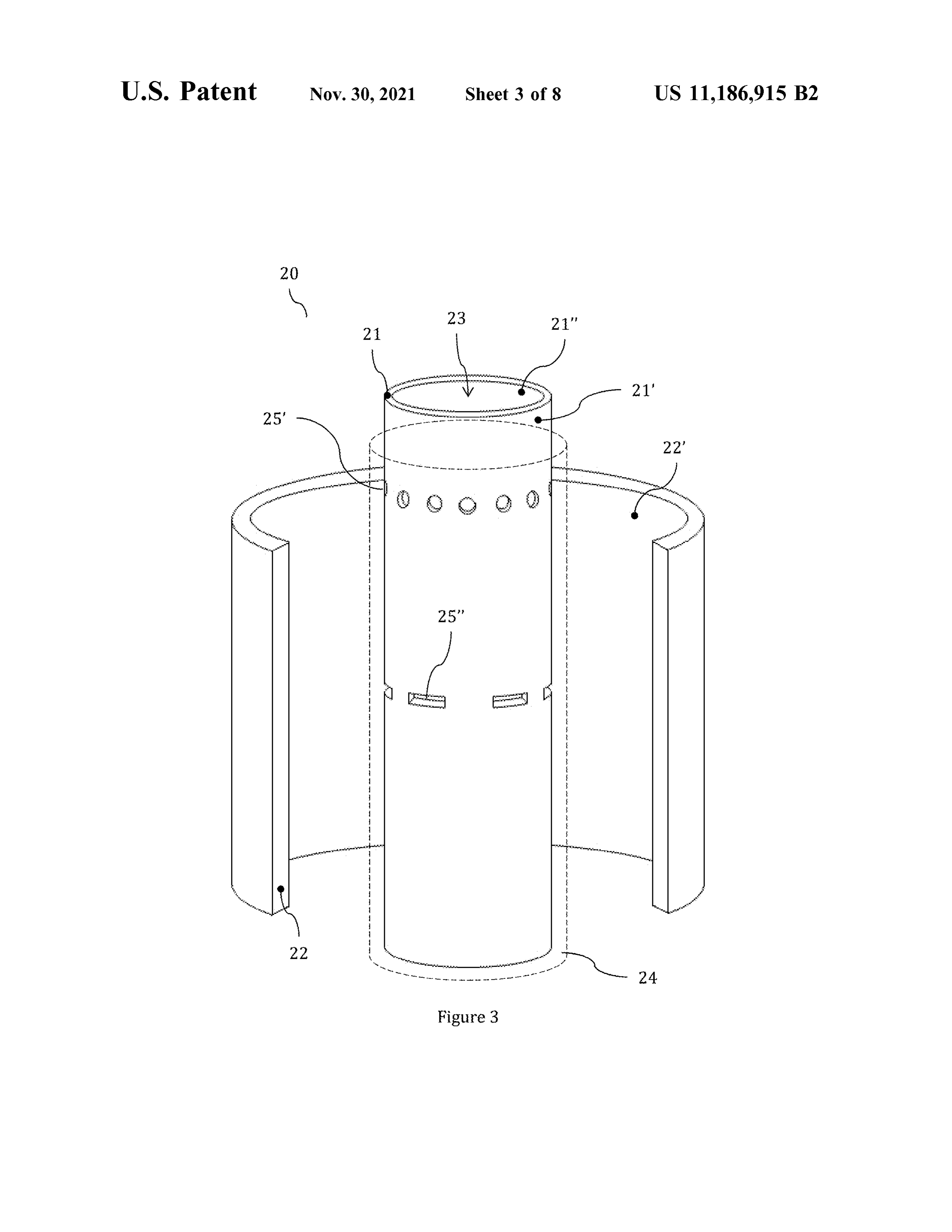
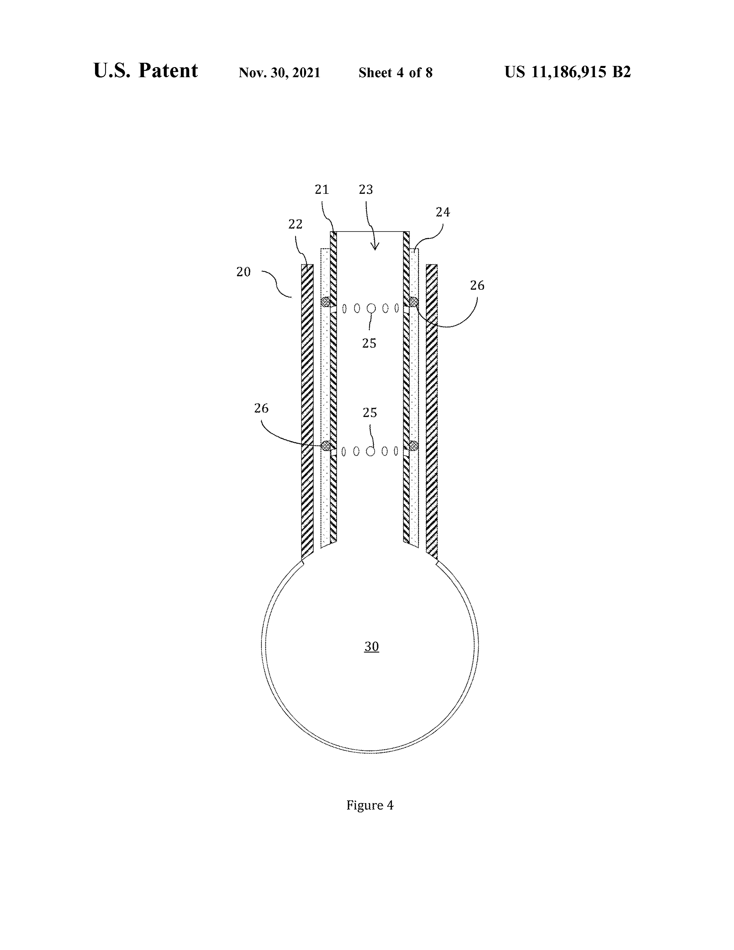
FIG . 3 shows a cross- section view of the electrodes of the 20 operates ing to its indesign a charge and discharge characteristics . FIGtransient . 2a alsoregime shows accord that the electrolytic cell according to an embodiment of the inven- electrolyzer 12 can comprise a second optional electrolytic tion . cell 13.2 connected in series with the first electrolytic cell FIG . 4 shows a cross - section view of a lower section of 13.1 in this case . Under this embodiment the energy source an electrolytic cell according to an embodiment of the 25 current 11 should be designed for the amplitude of the pulsing invention . wave may ensure that both the first and the second electrolytic cells 13.1 , 13.2 operate in charge and discharge
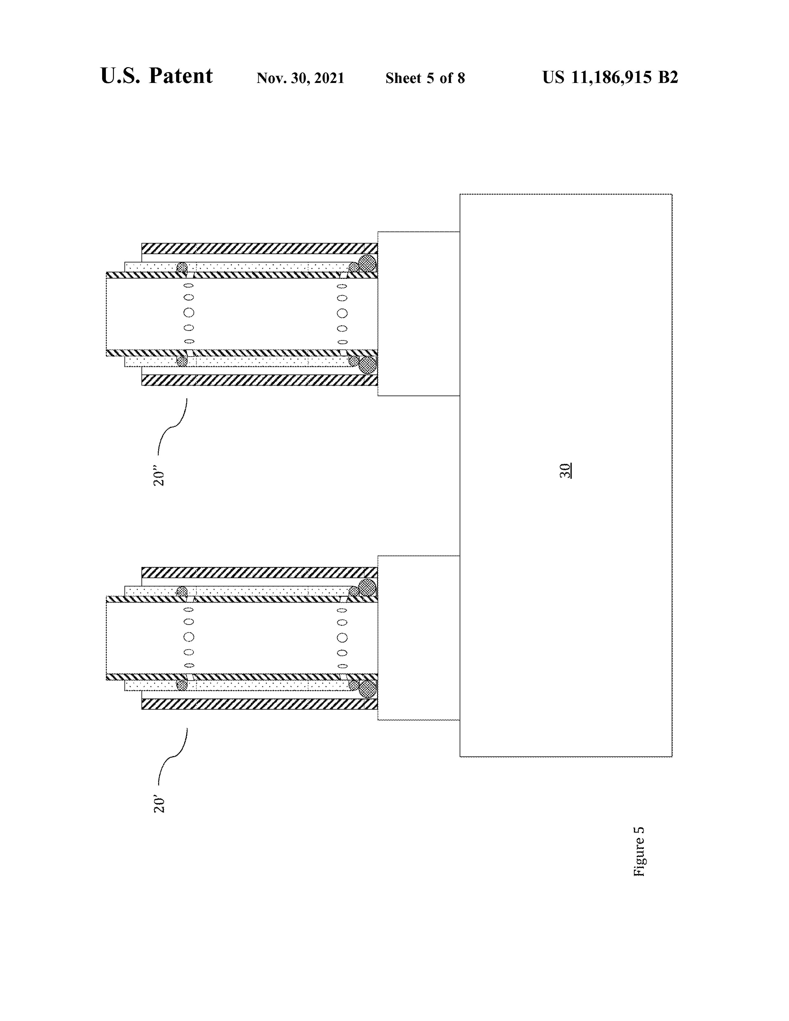
FIG . 5 shows a cross - section view of a lower section of transient regimes. Considering that both cells are connected two electrolytic cells according to an embodiment of the in series in this case , the operation thereof will be simulta invention . neous . If both cells 13.1 , 13.2 are identical, the distribution 30 of the voltage provided by the energy source 11 will be
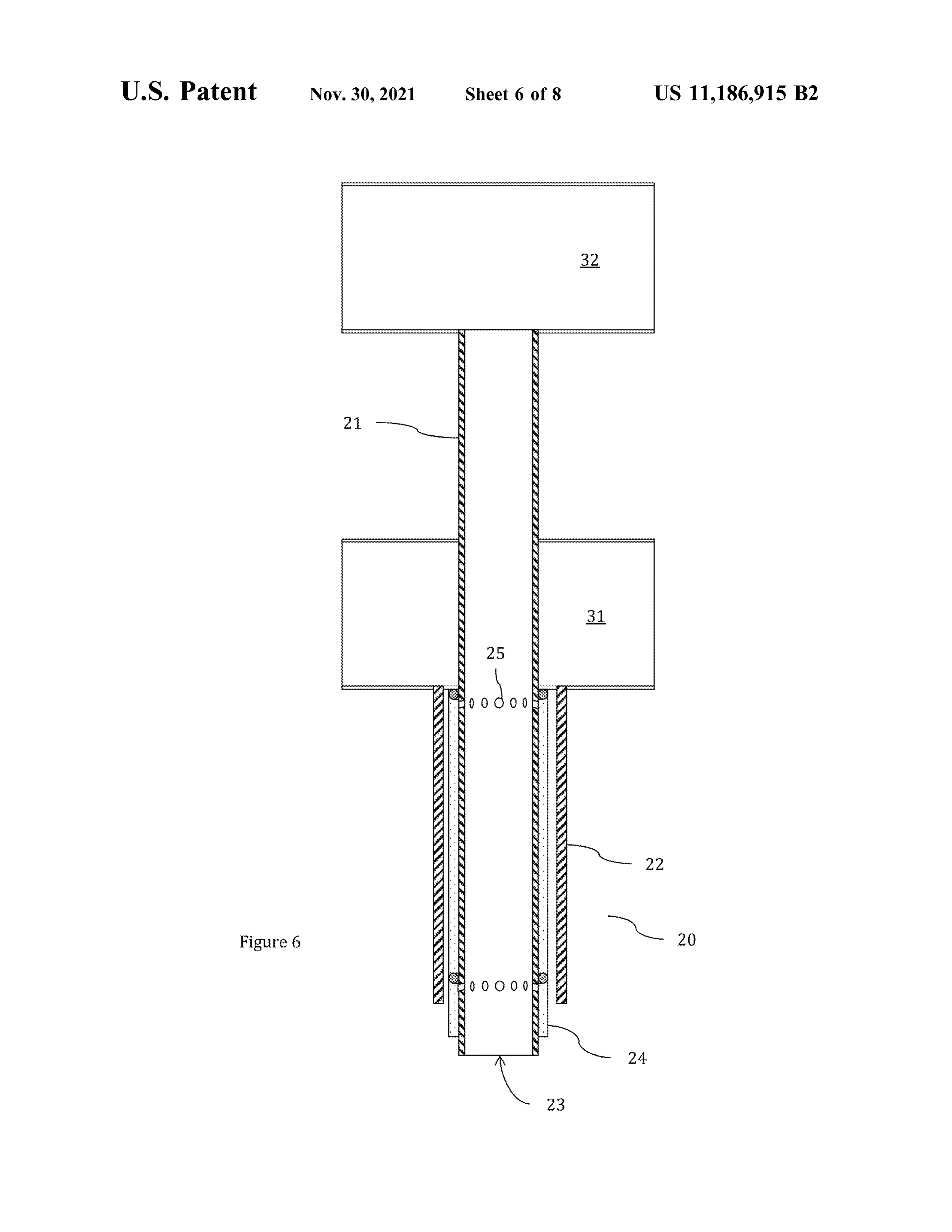
FIG . 6 shows a cross - section view of an upper section of equitable an electrolytic cell according to an embodiment of the Here it is important with both cells operating in an equivalent form . invention. to note that if additional electrolytic cells are connected in series, the energy source 11 shall be sized
FIG . 7 shows a perspective view of the electrolysis system in order to contribute the necessary energy to operate all according to an embodiment of the invention . 35 cells in series at the same time . FIG . 8 shows a perspective view of an electrolysis plant Additionally, FIG . 2b shows a scheme of an electrolysis according to an embodiment of the invention . system 10 ' comprising an energy source 11 ' , an electrolyzer 12 ' , a control unit 15 and at least one switch 16.1 . The
DETAILED DESCRIPTION OF THE
electrolyzer 12 ' comprises a first set of electrolytic cells
PREFERRED EMBODIMENT
40 14.1 , where said set formed by two or more electrolytic cells according to the invention is connected in series . Under this embodiment, the energy source 11 ' can be a direct current
FIGS . 1a and 1b show voltage versus time charts showing source providing direct current of a certain strength and the behavior of the electrical signal both on the supply side amplitude in order to operate the first set of electrolytic cells ( FIG . 1a ) and on the electrical charge side , i.e. on the 45 14.1 . The control unit 15 is configured in such a way to electrolytic cell side (FIG . 1b ) . As evidenced from FIG . 1a , control the activation or deactivation of a first switch 16.1 the form of the voltage signal on the supply side reflects the connected to the first set of cells , where said switch is in pulsing nature of the current, showing a maximum voltage charge of applying the current pulse over the first set of cells ( Vmar) that is kept for the duration ( 1) given by the D * T 14.1 when opening or closing the circuit . By the activation product, wherein D is the duration factor of the current pulse 50 and deactivation of the first switch 16.1 the current pulse and T is the pulsing wave period . Therefore, the distribution supplying the electrolytic cells connected in series of the of current delivered by the energy source is shown in a first set of cells 14.1 is generated. According to another scheme of current intervals over each electrolytic cell , embodiment, the electrolysis system 10 ' can comprise a showing a maximum voltage during part of the wave period second set of electrolytic cells 14.2 connected in parallel to and null voltage during the remaining part of said period. 55 the first set of cells 14.1 , with said second set being formed Additionally, FIG . 1b reflects that during the part of the in an equivalent form to the first set . According to this wave period where the maximum voltage is delivered , each embodiment, the electrolysis system 10 ' also comprises a electrolytic cell formed by the electrolysis system reaches a second switch 16.2 connected to the second set of cells in cell voltage V cel (DT) given by the cell charge acting as charge of operating in a similar form to that of the first capacitor when t-DT. In the chart of FIG . 1b it can be also 60 switch , but in relation to the second set of cells 14.2 . seen that once the duration of the current pulse ends in the According to this embodiment, the control unit 15 coordi step where the voltage delivered by the source is null — the nates the activation and deactivation of the first and second electrolytic cell starts its discharge phase , which ends with switches 16.1 and 16.2 for the first and second sets of cells the termination of the wave period and the start of a new 14.1 and 14.2 operate sequentially, taking advantage of the pulse , when t =T. At this time , the cell voltage is given by 65 connection in parallel to one single energy source 11 ' . Thus, Vce ( T ). The equations ruling the charge and discharge the same energy source 1l ' sized in order to provide current processes of the capacitor in terms of cell voltage are : voltage and flow to operate a set of cells in series can be
Page 17
operated to supply two sets of cells connected in parallel, In regard as openings , according to alternative embodi where in first place the first switch 16.1 is activated in order ments, they may be formed by circular holes 25 ' and /or to operate the first set of cells 14.1 and, once the switch has continuous grooves 25 " . The openings distribute along at been deactivated according to the duration required for the least one part of the central electrode 21 , preferably an upper pulse , the second switch 16.2 is activated in order to operate 5 part thereof, distributed in the extraction zones 27 provided the second set of cells 14.2 . Through the present embodi- to communicate the space between electrodes with the inner ment, the design of an electrolysis system is possible with space of the central electrode 21 .
multiple sets of electrolytic cells , supplying said cells by the The constructive aspects of the electrodes according to the activation and deactivation of multiple coordinated switches preferred embodiment allow taking advantage of the capaci to distribute the direct current from one single energy source 10 tive and resonant characteristics of the electrolytic cell , sequentially over the sets of cells . It is important to note that preventing the saturation of the walls of the electrodes with the design of said electrolysis plant depends on the optimum the gases generated by maximizing the cell's resonant duration and characteristics of the current pulse , in particular aspects, including the effect of overdamping and taking in regard to the pulse duration and frequency factor, which advantage of the diffusion and transfer of ions from one are obtained according to the approach of the present 15 electrode to other in the standby cycle given by the intervals invention . in the current supply of pulsing wave making use of the As an example, if the electrolyzer 12 ' comprises a first set cell's capacitive aspects .
of electrolytic cells 14.1 formed by 50 cells connected in FIG . 4 shows aa cross - section view of the lower part of an series, with each cell requiring a peak voltage of 2.5 V , a electrolytic cell 20 showing the preferred arrangement of the direct current source of 125v will be required to supply these 20 central electrode 21 , the outer electrode 22 , the separation 50 cells , distributing said 125 v in an equivalent form over mesh 24 and the inner space 23. Additionally, two extraction
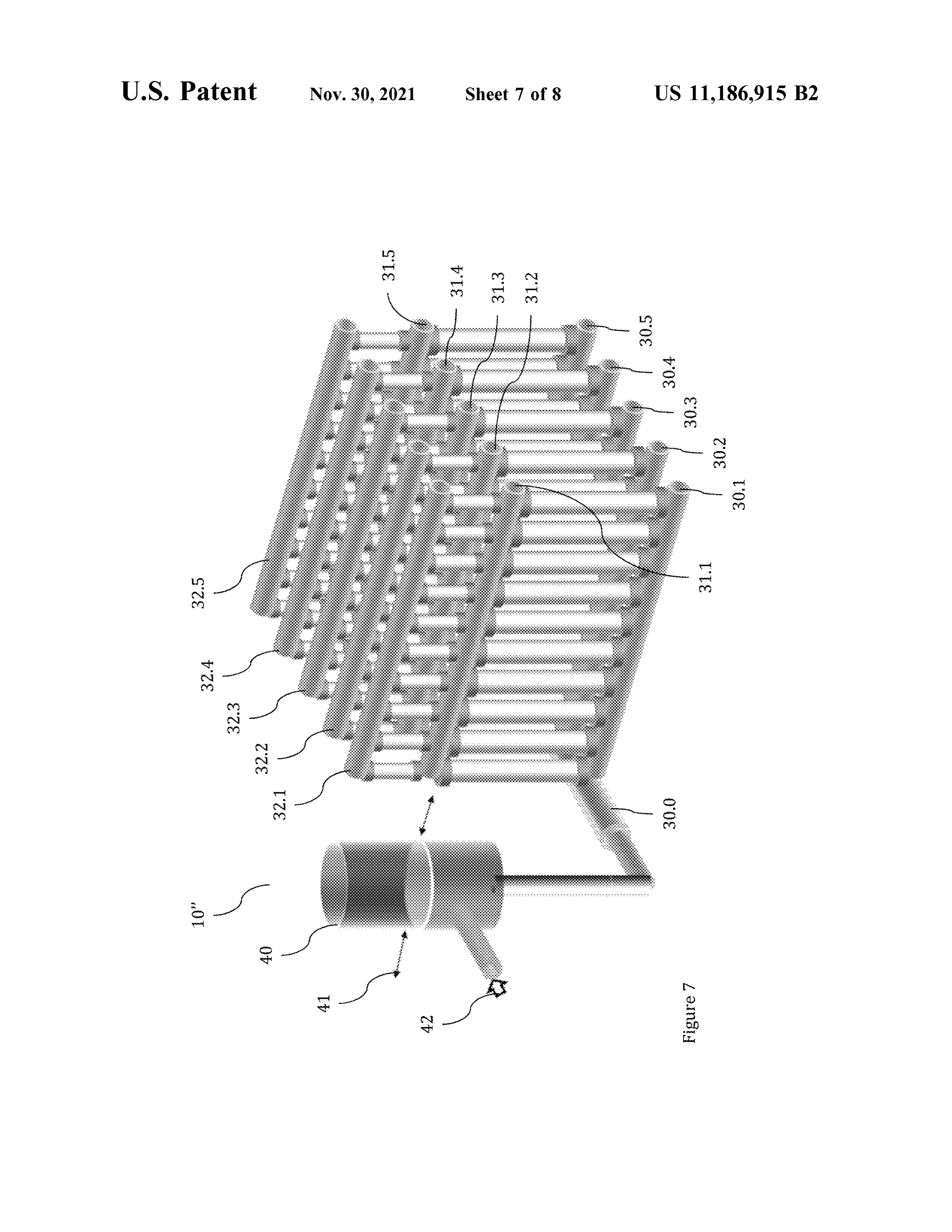
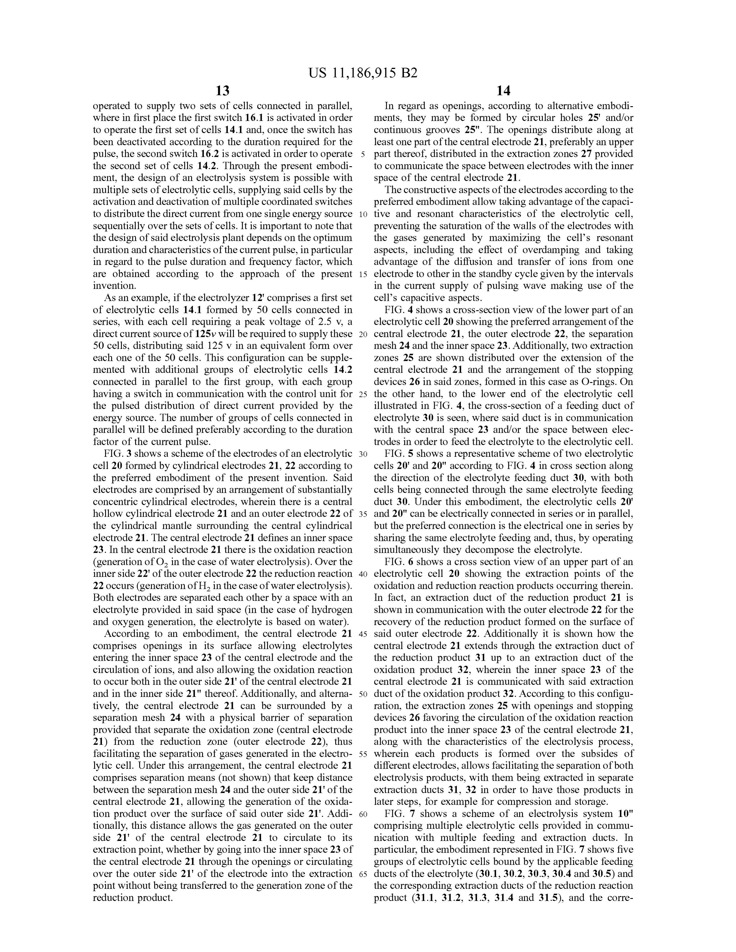
each one of the 50 cells . This configuration can be supple- zones 25 are shown distributed over the extension of the mented with additional groups of electrolytic cells 14.2 central electrode 21 and the arrangement of the stopping connected in parallel to the first group , with each group devices 26 in said zones , formed in this case as O -rings . On having a switch in communication with the control unit for 25 the other hand, to the lower end of the electrolytic cell the pulsed distribution of direct current provided by the illustrated in FIG . 4 , the cross - section of a feeding duct of energy source . The number of groups of cells connected in electrolyte 30 is seen , where said duct is in communication parallel will be defined preferably according to the duration with the central space 23 and / or the space between elec factor of the current pulse . trodes in order to feed the electrolyte to the electrolytic cell . FIG . 3 shows a scheme of the electrodes of an electrolytic 30 FIG . 5 shows a representative scheme of two electrolytic cell 20 formed by cylindrical electrodes 21 , 22 according to cells 20 ' and 20" according to FIG . 4 in cross section along the preferred embodiment of the present invention . Said the direction of the electrolyte feeding duct 30 , with both electrodes are comprised by an arrangement of substantially cells being connected through the same electrolyte feeding concentric cylindrical electrodes , wherein there is a central duct 30. Under this embodiment, the electrolytic cells 20 hollow cylindrical electrode 21 and an outer electrode 22 of 35 and 20" can be electrically connected in series or in parallel, the cylindrical mantle surrounding the central cylindrical but the preferred connection is the electrical one in series by electrode 21. The central electrode 21 defines an inner space sharing the same electrolyte feeding and , thus, by operating 23. In the central electrode 21 there is the oxidation reaction simultaneously they decompose the electrolyte . ( generation of O , in the case of water electrolysis ). Over the FIG . 6 shows a cross section view of an upper part of an inner side 22 ' of the outer electrode 22 the reduction reaction 40 electrolytic cell 20 showing the extraction points of the 22 occurs ( generation of H , in the case of water electrolysis ). oxidation and reduction reaction products occurring therein . Both electrodes are separated each other by a space with an In fact, an extraction duct of the reduction product 21 is electrolyte provided in said space ( in the case of hydrogen shown in communication with the outer electrode 22 for the and oxygen generation , the electrolyte is based on water) . recovery of the reduction product formed on the surface of According to an embodiment, the central electrode 21 45 said outer electrode 22. Additionally it is shown how the comprises openings in its surface allowing electrolytes central electrode 21 extends through the extraction duct of entering the inner space 23 of the central electrode and the the reduction product 31 up to an extraction duct of the circulation of ions , and also allowing the oxidation reaction oxidation product 32 , wherein the inner space 23 of the to occur both in the outer side 21 ' of the central electrode 21 central electrode 21 is communicated with said extraction and in the inner side 21 " thereof. Additionally, and alterna- 50 duct of the oxidation product 32. According to this configu tively, the central electrode 21 can be surrounded by a ration, the extraction zones 25 with openings and stopping separation mesh 24 with a physical barrier of separation devices 26 favoring the circulation of the oxidation reaction provided that separate the oxidation zone ( central electrode product into the inner space 23 of the central electrode 21 , 21 ) from the reduction zone (outer electrode 22 ) , thus along with the characteristics of the electrolysis process , facilitating the separation of gases generated in the electro- 55 wherein each products is formed over the subsides of lytic cell . Under this arrangement, the central electrode 21 different electrodes, allows facilitating the separation of both comprises separation means (not shown) that keep distance electrolysis products, with them being extracted in separate between the separation mesh 24 and the outer side 21 ' of the extraction ducts 31 , 32 in order to have those products in central electrode 21 , allowing the generation of the oxida- later steps, for example for compression and storage. tion product over the surface of said outer side 21 ' . Addi- 60 FIG . 7 shows a scheme of an electrolysis system 10 " tionally, this distance allows the gas generated on the outer comprising multiple electrolytic cells provided in commu side 21 ' of the central electrode 21 to circulate to its nication with multiple feeding and extraction ducts. In extraction point, whether by going into the inner space 23 of particular, the embodiment represented in FIG . 7 shows five the central electrode 21 through the openings or circulating groups of electrolytic cells bound by the applicable feeding over the outer side 21 ' of the electrode into the extraction 65 ducts of the electrolyte ( 30.1 , 30.2 , 30.3 , 30.4 and 30.5 ) and point without being transferred to the generation zone of the the corresponding extraction ducts of the reduction reaction reduction product. product (31.1 , 31.2 , 31.3 , 31.4 and 31.5 ) , and the corre
Page 18
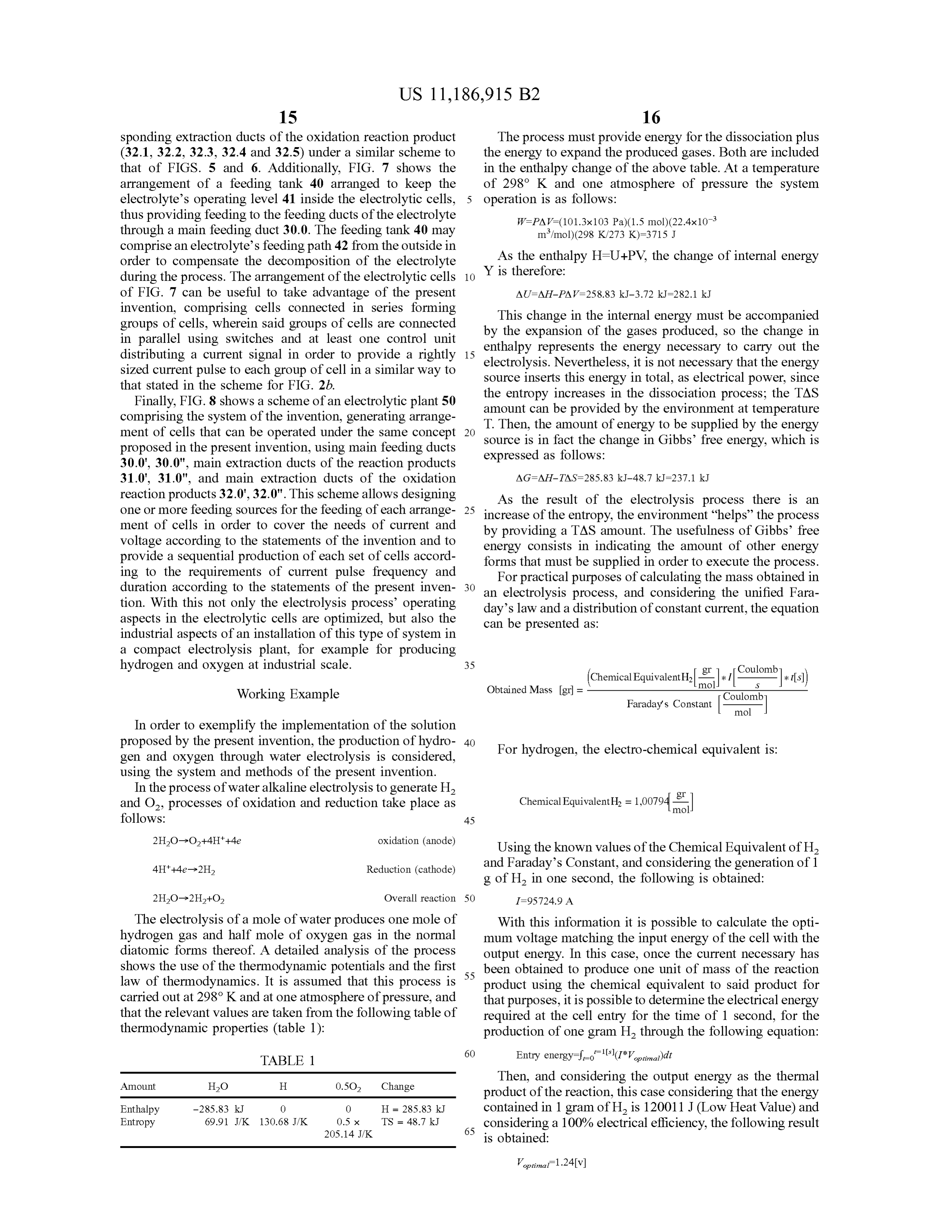
sponding extraction ducts of the oxidation reaction product The process must provide energy for the dissociation plus ( 32.1 , 32.2 , 32.3 , 32.4 and 32.5 ) under a similar scheme to the energy to expand the produced gases . Both are included that of FIGS . 5 and 6. Additionally, FIG . 7 shows the in the enthalpy change of the above table . At a temperature arrangement of a feeding tank 40 arranged to keep the of 298 ° K and one atmosphere of pressure the system electrolyte's operating level 41 inside the electrolytic cells , 5 operation is as follows:
thus providing feeding to the feeding ducts of the electrolyte W = PAV = (101.3x10³ Pa )( 1.5 mol ) (22.4x10⁻³ through a main feeding duct 30.0 . The feeding tank 40 may m3/mol)(298 K /273 K) =3715 J comprise an electrolyte's feeding path 42 from the outside in As the enthalpy H = U + PV, the change of internal energy order to compensate the decomposition of the electrolyte during the process. The arrangement of the electrolytic cells 10 Y is therefore :
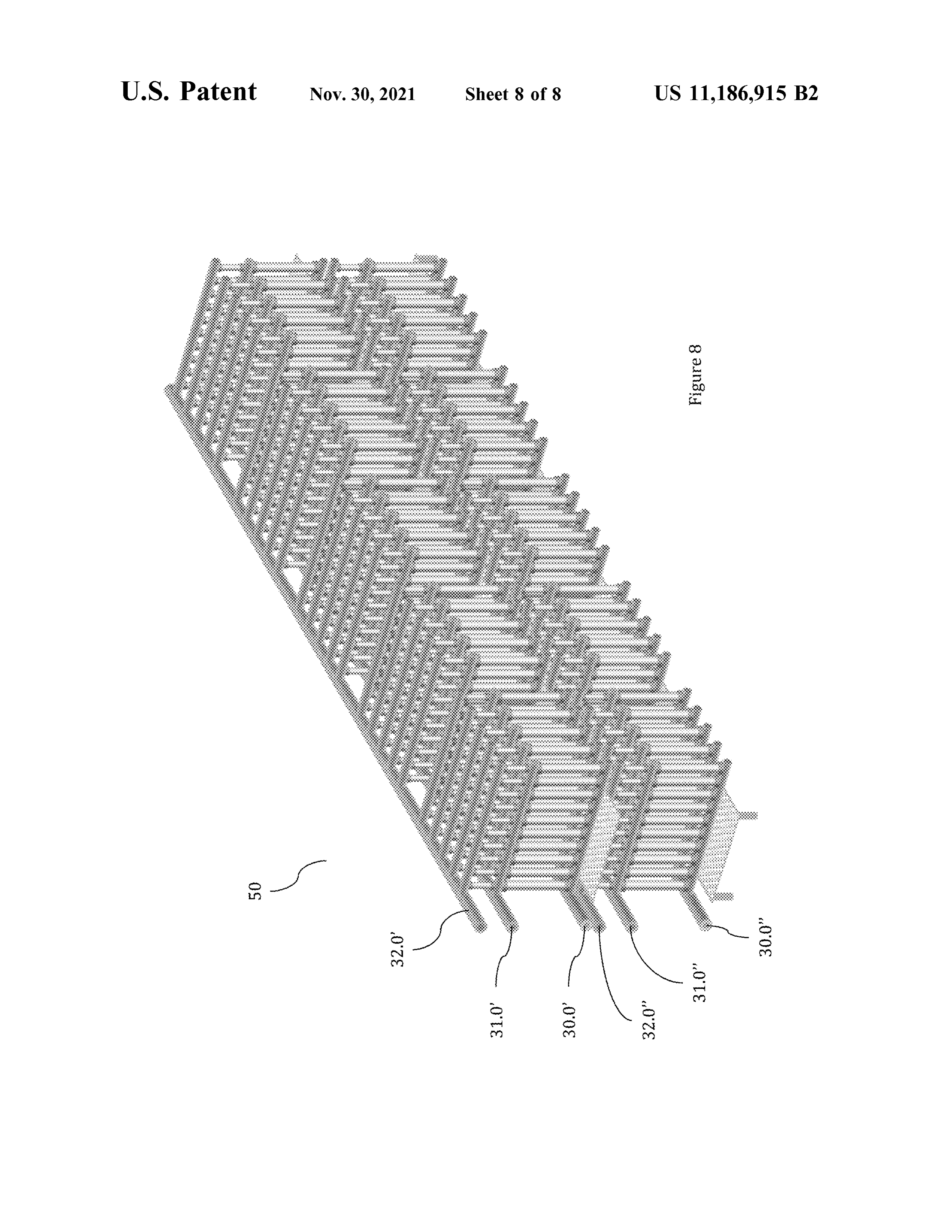
of FIG . 7 can be useful to take advantage of the present AU = AH - PAV = 258.83 kJ- 3.72 kJ = 282.1 kJ invention , comprising cells connected in series forming groups of cells , wherein said groups of cells are connected byThis change in the internal energy must be accompanied in parallel using switches and at least one control unit enthalpy representsofthe the expansion the gases produced, so the change in energy necessary to carry out the distributing a current signal in order to provide a rightly 15 sized current pulse to each group of cell in aa similar way to source inserts this energy, init istotal electrolysis . Nevertheless not necessary that the energy , as electrical power, since that stated in the scheme for FIG . 2b. the entropy increases in the dissociation process ; the TAS Finally, FIG . 8 shows a scheme of an electrolytic plant 50 amount can be provided by the environment comprising the system of the invention , generating arrange T. Then , the amount of energy to be suppliedatbytemperature ment of cells that can be operated under the same concept 20 source is in fact the change in Gibbs ' free energythe energy , which is proposed in the present invention , using main feeding ducts expressed as follows:
30.0 ' , 30.0 " , main extraction ducts of the reaction products 31.0 ' , 31.0 " , and main extraction ducts of the oxidation AG = AH - TAS = 285.83 kJ- 48.7 kJ = 237.1 kJ reaction products 32.0 ' , 32.0 " . This scheme allows designing As the result of the electrolysis process there is an one or more feeding sources for the feeding of each arrange- 25 increase of the entropy, the environment “ helps ” the process ment of cells in order to cover the needs of current and voltage according to the statements of the invention and to by providing a TAS amount. The usefulness of Gibbs ' free provide a sequential production of each set of cells accord energy consists in indicating the amount of other energy ing to the requirements of current pulse frequency and forms that must be supplied in order to execute the process . duration according to the statements of the present inven- 30 an For practical purposes of calculating the mass obtained in tion . With this not only the electrolysis process ' operating day's law and a process electrolysis , and considering the unified Fara distribution of constant current, the equation aspects in the electrolytic cells are optimized, but also the can be presented as :
industrial aspects of an installation of this type of system in a compact electrolysis plant, for example for producing hydrogen and oxygen at industrial scale . 35 Coulomb Working Example Obtained Mass [ gr ] ( Chemical Equivalent H, (01-11
mol
Coulomb
Faraday's Constant mol
In order to exemplify the implementation of the solution proposed by the present invention , the production of hydro- 40 For hydrogen, the electro - chemical equivalent is : gen and oxygen through water electrolysis is considered , using the system and methods of the present invention .
In the process of water alkaline electrolysis to generate H2 gr and O2 , processes of oxidation and reduction take place as Chemical Equivalent H2 = 1,00794(mol follows: 45 2H20O2 + 4H * + 4e oxidation ( anode) Using the known values of the Chemical Equivalent of H2 4H + + 4e - 2H2 Reduction ( cathode) and Faraday's Constant, and considering the generation of 1 g of H , in one second, the following is obtained :
2H20-2H2 + O2 Overall reaction 50 1= 95724.9 A
The electrolysis of a mole of water produces one mole of With this information it is possible to calculate the opti hydrogen gas and half mole of oxygen gas in the normal mum voltage matching the input energy of the cell with the diatomic forms thereof. A detailed analysis of the process output energy. In this case , once the current necessary has shows the use of the thermodynamic potentials and the first law of thermodynamics. It is assumed that this process is 55 been obtained to produce one unit of mass of the reaction product using the chemical equivalent to said product for carried out at 298 ° K and at one atmosphere of pressure, and that purposes, it is possible to determine the electrical energy that the relevant values are taken from the following table of required at the cell entry for the time of 1 second , for the thermodynamic properties ( table 1 ) : production of one gram H2 through the following equation :
TABLE 1
Then, and considering the output energy as the thermal product of the reaction , this case considering that the energy
Enthalpy
Entropy
contained in 1 gram of H , is 120011 J (Low Heat Value) and 65 considering a 100 % electrical efficiency, the following result
Page 19
Here it is important to note that the electrolysis process for Therefore, the duration of the pulse wave is : the generation of hydrogen is widely known ; thus, it is not an object of the present invention to restate the thermody namics balances and equations associated with said process . D*T=
Without prejudice to that and as shown by the present 5 Vmax example of application , the optimum application to favor reactions in the production of hydrogen through electrolysis is about 1.24 volts , so that to obtain the maximum efficiency Then, the current flowing through the cell under these of energy transformation . design parameters is configured as :
The optimum voltage can be also obtained by applying the standard potentials of reduction corresponding to the 10 potentials measured in each electrode to favor the reduction DIf [[ A ]
(Vmax *voilécle4 and oxidation processes under standard conditions . Using laverage- e RC 1,8 the standard potentials of reduction, it can be defined that the oxidation reactions in the anode ( 2H2O = 02 + 4H * + 4e ) has a reduction potential of 1.229 V , while the reduction reaction 15 in the cathode ( 4H * + 4e2H2) has a potential of 0 V , with Obtaining the current values for several values of V???
this valued being defined as the reduction potential in Considering a power supply with V,max= 2.52 v is it reference . Then , it is possible to calculate the potential of the possible to determine that the pulse duration factor is cell (Eceli') as follows:
20 D ~ 0.24 for the optimum voltage desired . Then , considering
Ecellº9 = Ecathode - Eanode the equation for the period and frequency and a high Wherein E cathode and Eanode correspond to the potential capacitance
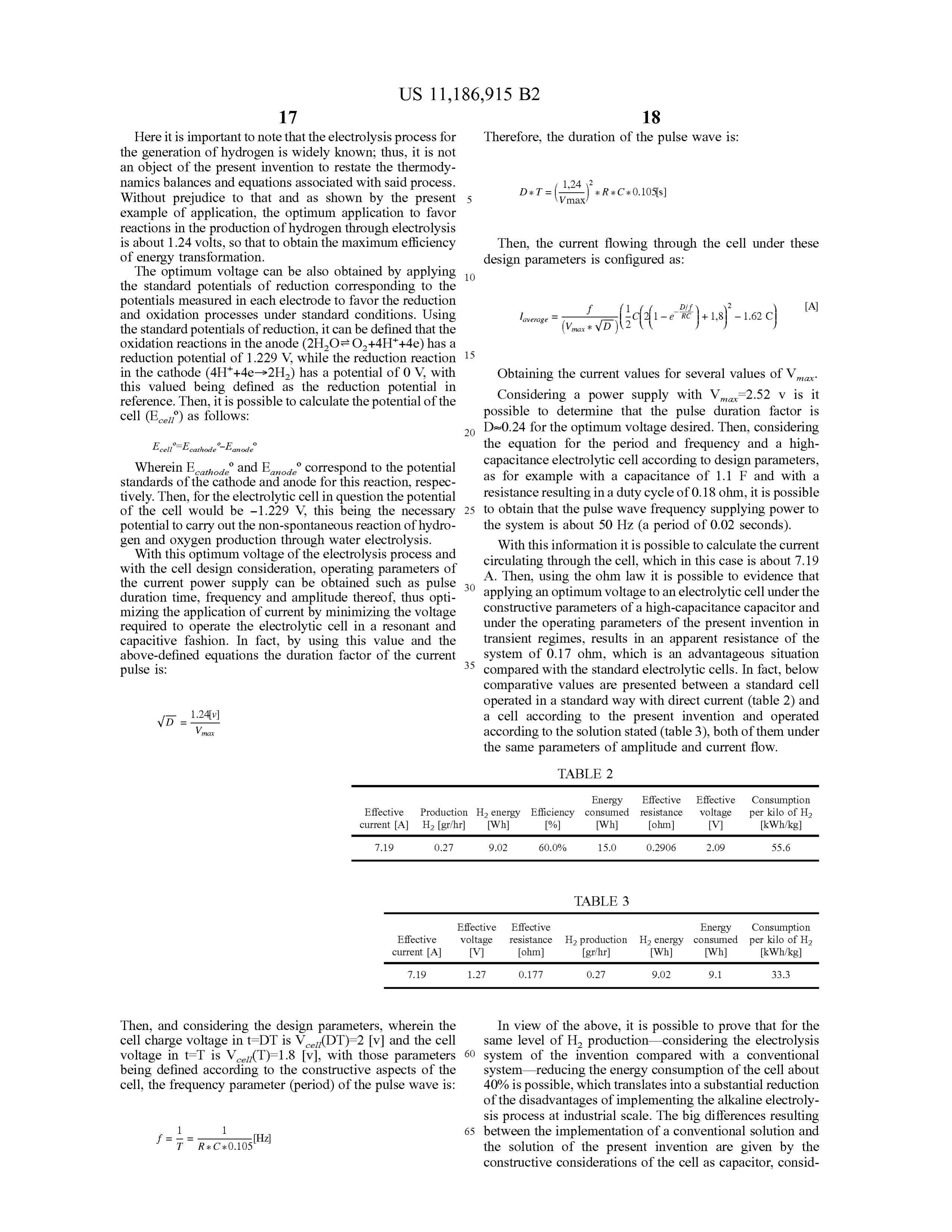
as for electrolytic cell according to design parameters, example with a capacitance of 1.1 F and with a standards of the cathode and anode for this reaction , respec tively . Then, for the electrolytic cell in question the potential resistance resulting in a duty cycle of 0.18 ohm , it is possible of the cell would be -1.229 V , this being the necessary 25 to obtain that the pulse wave frequency supplying power to potential to carry out the non -spontaneous reaction of hydro- the system is about 50 Hz ( a period of 0.02 seconds ) . gen and oxygen production through water electrolysis. With this information it is possible to calculate the current With this optimum voltage of the electrolysis process and circulating through the cell , which in this case is about 7.19 with the cell design consideration, operating parameters of A. Then , using the ohm law it is possible to evidence that theduration currenttimepower supply can be obtained such as pulse , frequency and amplitude thereof, thus opti 30 applying an optimum voltage to anelectrolytic cell underthe mizing the application of current by minimizing the voltage constructive parameters of a high -capacitance capacitor and required to operate the electrolytic cell in a resonant and under the operating parameters of the present invention in capacitive fashion . In fact, by using this value and the transient regimes, results in an apparent resistance of the above -defined equations the duration factor of the current 35 system of 0.17 ohm , which is an advantageous situation pulse is : compared with the standard electrolytic cells . In fact, below comparative values are presented between a standard cell operated in aa standard way with direct current ( table 2 ) and
= a cell according to the present invention and operated Vmax according to the solution stated (table 3 ) , both of them under the same parameters of amplitude and current flow .
TABLE 2
Energy Effective Effective Consumption
Effective Production H, energy Efficiency consumed resistance voltage per kilo of H2 current [ A ] H2 [ gr /hr] [Wh] [%] [Wh ] [ ohm ] [V] [kWh /kg] 7.19 0.27 9.02 60.0 % 15.0 0.2906 2.09 55.6
TABLE 3
Effective Effective Energy Consumption
Effective voltage resistance H2 production H? energy consumed per kilo of H2 current [A] [V] [ ohm ] [ gr /hr ] [Wh] [Wh ] [kWh /kg]
Then , and considering the design parameters, wherein the In view of the above , it is possible to prove that for the cell charge voltage in t =DT is V ceu (DT)= 2 [v ] and the cell same level of H , production considering the electrolysis voltage in t=T is Vce ( T ) = 1.8 [v] , with those parameters 60 system of the invention compared with a conventional being defined according to the constructive aspects of the system - reducing the energy consumption of the cell about cell , the frequency parameter (period ) of the pulse wave is : 40% is possible , which translates into aa substantial reduction of the disadvantages of implementing the alkaline electroly sis process at industrial scale . The big differences resulting 65 between the implementation of a conventional solution and sak 1
R * C * 0.105[ Hz ] the solution of the present invention are given by the constructive considerations of the cell as capacitor, consid
Page 20
ering the capacitive and inductive aspects , along with the wherein the direct current pulse comprises an amplitude , resistive ones in order to operate the cell under charge and the duration and the frequency ( f) determined such that discharge transient regimes. This approach results in current each electrolytic cell of the electrolyzer is energized in peaks over the electrolytic cell at the beginning of each its corresponding charge and discharge transient charge period, which reflects in an apparent or reduce 5 regimes.
effective resistance, in this case about 0.17 ohm . Taking 2. The system according to claim 1 , wherein the central advantage of said current peak through supplying pulse electrode wave and operation under transient regimes translates into inner spaceis, awherein hollow cylindrical electrode that defines an a reduction reaction takes place over increased efficiency, which exceeds the operation of a con the inner side of the outer electrode and an oxidation ventional productioncellof and makingandtheoxygen hydrogen industrialin solutions an alkalineforway the 10 reaction takes place over an outer side of the central elec competitive. trode, wherein the oxidation reaction takes place alterna At this point it should be highlighted that the preceding tively over the inner side of the central electrode ; example of application can be extrapolated to other elec wherein the system further comprising trolysis processes, being relevant to calculate the optimal 15 one or more first extraction ducts for extraction of a voltage of this process and consider the transient regimes of product of the oxidation reaction, wherein each of the electrolytic cell both in charge as in discharge, where the the first extraction ducts is in communication with capacitive, inductive and resonant aspects of said cell should the inner space of the central electrode ; and be stressed . one or more second extraction ducts for extraction of a 20 product of the reduction reaction, wherein each of
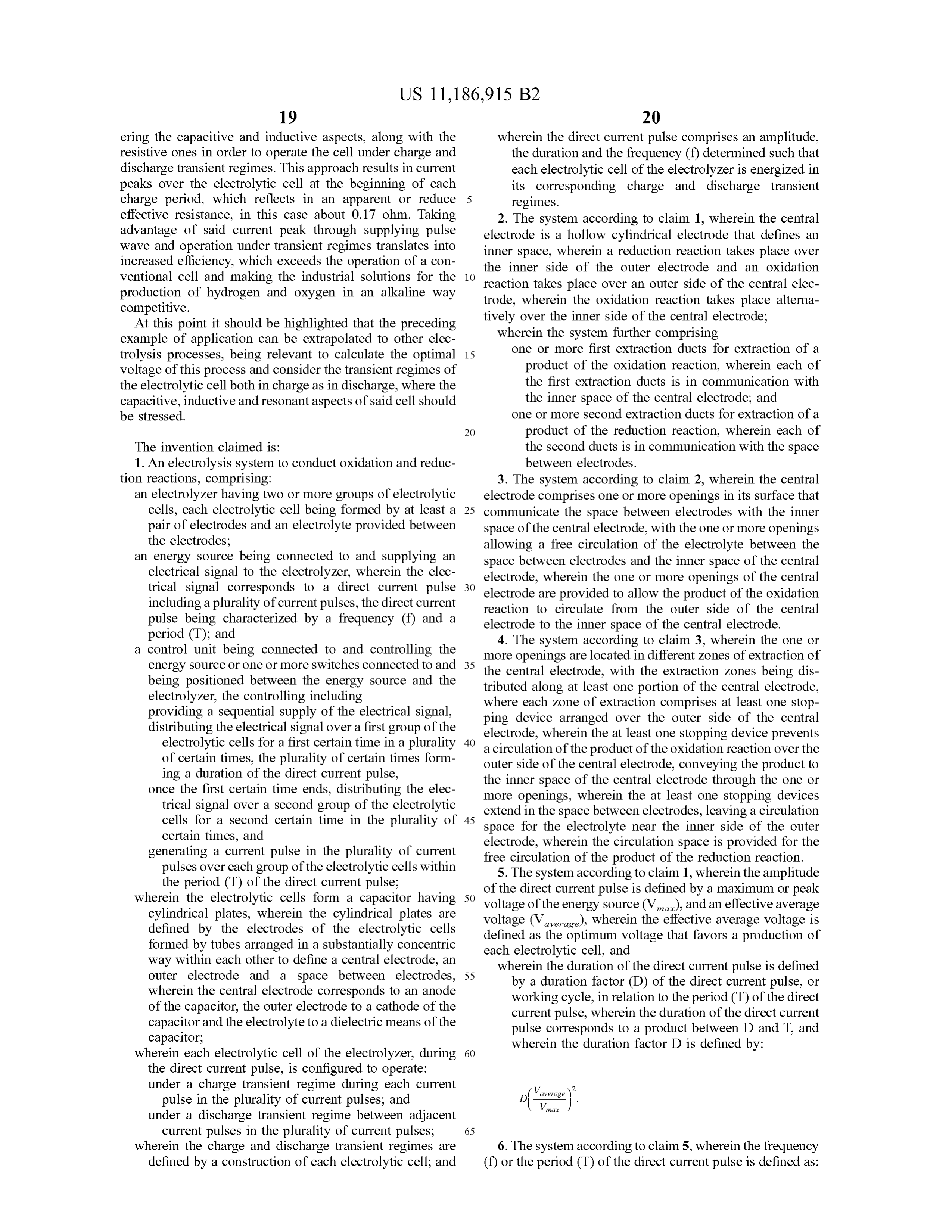
The invention claimed is : the second ducts is in communication with the space 1. An electrolysis system to conduct oxidation and reduc between electrodes .
tion reactions, comprising: 3. The system according to claim 2 , wherein the central an electrolyzer having two or more groups of electrolytic electrode comprises one or more openings in its surface that cells , each electrolytic cell being formed by at least a 25 communicate the space between electrodes with the inner pair of electrodes and an electrolyte provided between space of the central electrode, with the one or more openings the electrodes;
an energy source being connected to and supplying an allowing space a free circulation of the electrolyte between the between electrodes and the inner space of the central electrical signal to the electrolyzer, wherein the elec electrode, wherein the one or more openings of the central trical signal including corresponds a plurality to pulses of current a direct, thecurrent pulse 30 electrode are provided direct current to allow the product of the oxidation reaction to circulate from the outer side of the central pulse being characterized by a frequency ( f) and a electrode to the inner space of the central electrode. period (T) ; and 4. The system according to claim 3 , wherein the one or a control unit being connected to and controlling the more openings are located in different zones of extraction of energy source or one or more switches connected to and being positioned between the energy source and the tributed along35 the central electrode, with the extraction zones being dis electrolyzer, the controlling including at least one portion of the central electrode, providing a sequential supply of the electrical signal, where ping each zone of extraction comprises at least one stop device arranged over the outer side of the central distributing the electrical signal over a first group of the electrode, wherein the at least one stopping device prevents electrolytic cells for aa first certain time in a plurality 40 a circulation of the product of the oxidation reaction over the of certain times , the plurality of certain times form outer side of the central electrode , conveying the product to ing a duration of the direct current pulse , once the first certain time ends, distributing the elec more openings , wherein the at least onethrough the inner space of the central electrode stopping the one or devices trical signal over a second group of the electrolytic extend in the space between electrodes, leaving a circulation cells for a second certain time in the plurality of 45 space for the electrolyte near the inner side of the outer certain times , and electrode, wherein the circulation space is provided for the generating a current pulse in the plurality of current free circulation of the product of the reduction reaction . pulses over each group of the electrolytic cells within 5. The system according to claim 1 , wherein the amplitude the period (T ) of the direct current pulse ;
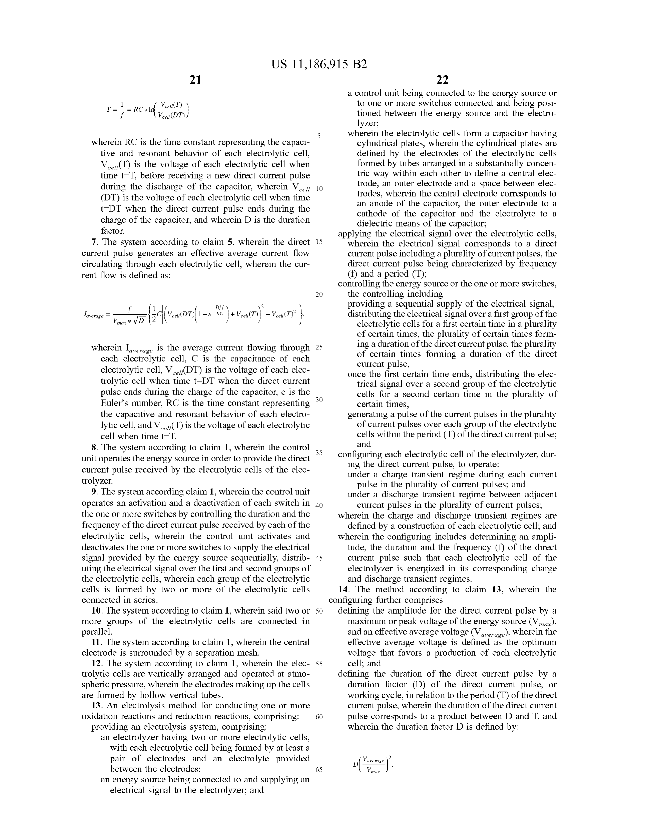
wherein the electrolytic cells form a capacitor having 50 voltagedirect of the current pulse is defined by a maximum or peak cylindrical plates , wherein the cylindrical plates are voltage of(Vaverage the energy source ( Vmax ), and an effective average ), wherein the effective average voltage is defined by the electrodes of the electrolytic cells defined as the optimum formed by tubes arranged in a substantially concentric each electrolytic cell , andvoltage that favors a production of way within each other to define a central electrode, an outer electrode and a space between electrodes, 55 wherein by a the duration of the direct current pulse is defined duration factor (D ) of the direct current pulse , or wherein the central electrode corresponds to an anode working cycle , in relation to the period ( T ) of the direct of the capacitor, the outer electrode to a cathode of the current pulse , wherein the duration of the direct current capacitor and the electrolyte to a dielectric means of the pulse corresponds to a product between D and T, and capacitor; wherein the duration factor D is defined by : wherein each electrolytic cell of the electrolyzer, during 60 the direct current pulse , is configured to operate :
under a charge transient regime during each current V average pulse in the plurality of current pulses ; and under a discharge transient regime between adjacent
current pulses in the plurality of current pulses ; 65 wherein the charge and discharge transient regimes are 6. The system according to claim 5 , wherein the frequency defined by a construction of each electrolytic cell ; and ( f) or the period (T ) of the direct current pulse is defined as :
Page 21
a control unit being connected to the energy source or to one or more switches connected and being posi
T=*=RC# ld Vceu(T) tioned between the energy source and the electro lyzer ;
5 wherein the electrolytic cells form a capacitor having wherein RC is the time constant representing the capaci cylindrical plates , wherein the cylindrical plates are tive and resonant behavior of each electrolytic cell , defined by the electrodes ofa the electrolytic cells Vceti (T ) is the voltage of each electrolytic cell when formed by tubes arranged in a substantially concen time t = T , before receiving a new direct current pulse tric way within each other to define a central elec during the discharge of the capacitor, wherein Vcell 10 trode, an outer electrode and a space between elec (DT ) is the voltage of each electrolytic cell when time trodes , wherein the central electrode corresponds to t=DT when the direct current pulse ends during the an anode of the capacitor, the outer electrode to a charge of the capacitor, and wherein D is the duration cathode of the capacitor and the electrolyte to a factor.
dielectric means of the capacitor ;
applying the electrical signal over the electrolytic cells , 7. The system according to claim 5 , wherein the direct 15 wherein the electrical signal corresponds to a direct current pulse generates an effective average current flow current pulse including a plurality of current pulses , the circulating through each electrolytic cell , wherein the cur- direct current pulse being characterized by frequency rent flow is defined as : ( f) and a period ( T ) ; controlling the energy source or the one or more switches , 20 the controlling including providing a sequential supply of the electrical signal, laverage f
Dif -e RC + ( T) distributing the electrical signal over a first group of the electrolytic cells for aa first certain time in a plurality of certain times , the plurality of certain times form wherein Iaverage is the average current flowing through 25 ing a duration of the direct current pulse , the plurality each electrolytic cell , C is the capacitance of each of certain times forming a duration of the direct electrolytic cell , V ced (DT) is the voltage of each elec current pulse , trolytic cell when time t =DT when the direct current once the first certain time ends , distributing the elec pulse ends during the charge of the capacitor, e is the 30 trical signal over a second group of the electrolytic cells for a second certain time in the plurality of
Euler's number, RC is the time constant representing certain times , the capacitive and resonant behavior of each electro generating a pulse of the current pulses in the plurality lytic cell , and V celi ( T ) is the voltage of each electrolytic of current pulses over each group of the electrolytic cell when time t=T. cells within the period ( T ) of the direct current pulse ; 8. The system according to claim 1 , wherein the control 35 and unit operates the energy source in order to provide the direct configuring each electrolytic cell of the electrolyzer, dur current pulse received by the electrolytic cells of the elec ing the direct current pulse , to operate : trolyzer. under a charge transient regime during each current pulse in the plurality of current pulses ; and 9. The system according claim 1 , wherein the control unit under a discharge transient regime between adjacent operates an activation and aa deactivation of each switch in 40 current pulses in the plurality of current pulses ; the one or more switches by controlling the duration and the wherein the charge and discharge transient regimes are frequency of the direct current pulse received by each of the defined by a construction of each electrolytic cell ; and electrolytic cells , wherein the control unit ac ates and wherein the configuring includes determining an ampli deactivates the one or more switches to supply the electrical tude, the duration and the frequency ( f) of the direct
signal provided by the energy source sequentially, distrib- 45 current pulse such that each electrolytic cell of the uting the electrical signal over the first and second groups of electrolyzer is energized in its corresponding charge the electrolytic cells , wherein each group of the electrolytic and discharge transient regimes.
cells is formed by two or more of the electrolytic cells 14. The method according to claim 13 , wherein the connected in series. configuring further comprises 10. The system according to claim 1 , wherein said two or 50 defining the amplitude for the direct current pulse by a more groups of the electrolytic cells are connected in maximum or peak voltage of the energy source (Vmax ), parallel and an effective average voltage ( Vaverage ), wherein the 11. The system according to claim 1 , wherein the central effective average voltage is defined as the optimum electrode is surrounded by a separation mesh . voltage that favors a production of each electrolytic 12. The system according to claim 1 , wherein the elec- 55 cell ; and trolytic cells are vertically arranged and operated at atmo- defining the duration of the direct current pulse by a spheric pressure , wherein the electrodes making up the cells duration factor (D ) of the direct current pulse , or are formed by hollow vertical tubes . working cycle , in relation to the period ( T ) of the direct 13. An electrolysis method for conducting one or more current pulse , wherein the duration of the direct current oxidation reactions and reduction reactions, comprising: 60 pulse corresponds to a product between D and T, and providing an electrolysis system , comprising: wherein the duration factor D is defined by : an electrolyzer having two or more electrolytic cells , with each electrolytic cell being formed by at least a pair of electrodes and an electrolyte provided between the electrodes ;
an energy source being connected to and supplying an
electrical signal to the electrolyzer, and
Page 22
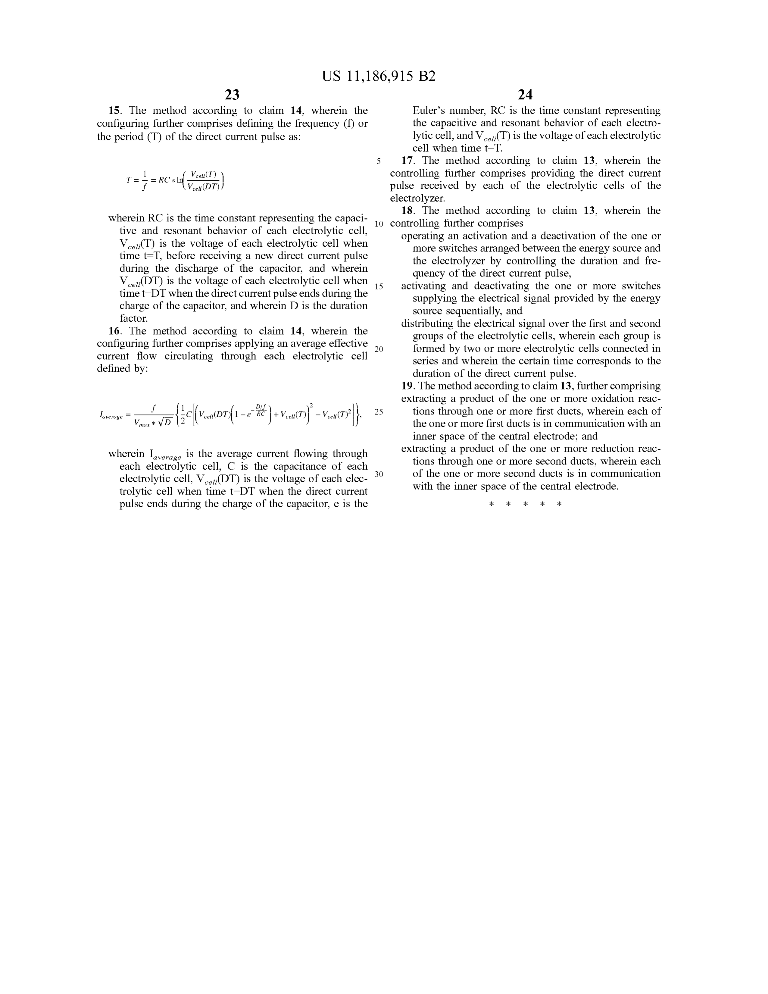
15. The method according to claim 14 , wherein the Euler's number, RC is the time constant representing configuring further comprises defining the frequency ( f) or the capacitive and resonant behavior of each electro the period ( T ) of the direct current pulse as : lytic cell , and V cet ( T ) is the voltage of each electrolytic cell when time t=T.
5 17. The method according to claim 13 , wherein the2
V cell( T ) controlling further comprises providing the direct current
= RC * In Vcel (DT) pulse received by each of the electrolytic cells of the electrolyzer 18. The method according to claim 13 , wherein the wherein RC is the time constant representing the capaci 10 controlling tive and resonant behavior of each electrolytic cell , further comprises
Vce ( T ) is the voltage of each electrolytic cell when operating an activation and a deactivation of the one or time t = T, before receiving a new direct current pulse more switches arranged between the energy source and during the discharge of the capacitor, and wherein the electrolyzer by controlling the duration and fre quency of the direct
V cell(DT) is the voltage of each electrolytic cell when 15 activating and deactivating current pulse , time t = DT when the direct current pulse ends during the the one or more switches supplying the electrical signal provided by the energy charge of the capacitor, and wherein D is the duration source sequentially, and factor. distributing the electrical signal over the first and second 16. The method according to claim 14 , wherein the groups of the electrolytic cells , wherein each group is configuring further comprises applying an average effective 20 formed by two or more electrolytic cells connected in current flow circulating through each electrolytic cell series and wherein the certain time corresponds to the defined by: duration of the direct current pulse . 19. The method according to claim 13 , further comprising extracting a product of the one or more oxidation reac
Vmax * VD -e RC + tions through one or more first ducts, wherein each of the one or more first ducts is in communication with an inner space of the central electrode; and wherein Iaverage is the average current flowing through extracting a product of the one or more reduction reac each electrolytic cell , C is the capacitance of each 30 tions through one or more second ducts, wherein each electrolytic cell , V celi(DT) is the voltage of each elec of the one or more second ducts is in communication trolytic cell when time t =DT when the direct current with the inner space of the central electrode . pulse ends during the charge of the capacitor, e is the
Provenance
- Collection
- Patents citing this work
- Original assignee
- Ulyzer Holding Ag
- Pages
- 22
- Method
- pdftotext (the PDF's own text layer) + pdftoppm 300dpi page scans
- Patent office record
- patents.google.com →
- Source
- Google Patents citing-documents table
- Inventors
- Jorge Garcés Barón; Ulyzer Holding Ag
- Published
- 2021-11-30
- Transcribed from
- patentimages.storage.googleapis.com →