patent · GB2467187A
Device for the separation of elements from a compound using harmonic frequencies
28 July 2010
Page 1 — bibliographic record
oy» UK Patent Application «GB 2467187
(43) Date of A Publication
(21) Application No:
(30) Priority Data:
Michael Barry Wright
Baytree House, 33 Moor Lane, MARTIN,
Lincolnshire, LN4 3RB, United Kingdom
(continued on next page)
(56) Documents Cited:
(58) Field of Search:
INT CL C25B
Other: WPI, EPRODOC and XPESP
(54) Title of the Invention: Invention for periodic element/s extraction
Abstract Title: Device for the separation of elements from a compound using harmonic frequencies
(57) The device described separates elements from a compound using resonance frequencies and multiples of the resonance frequencies (harmonic frequencies) of the elements required, via electrically conductive elements of the same material set at optimum resonance transfer distances.
Water may be separated into constituent elements of hydrogen and oxygen, where the hydrogen may be used an on-demand energy source. The resonance or harmonic frequencies may be applied via audio speakers.
Laas
Hylloxgn Seconance Preaioney
Hes
ogan iaarnane Renny §
This print incorporates corrections made under Section 117(1) of the Patents Act 1977.
The claims were filed later than the filing date but within the period prescribed by Rule 22(1) of the Patents Rules 2007.
This print takes account of replacement documents submitted after the date of filing to enable the application to comply
with the formal requirements of the Patents Rules 2007.
Page 2
GB 2467187 A continuation
Michael Barry Wright
(74) Agent and/or Address for Service: Michael Barry Wright
Baytree House, 33 Moor Lane, MARTIN, Lincolnshire, LN4 3RB, United Kingdom

Page 3
perere sey ean de wua azwea aewee ieuern comes eamee aber eaae ae seedy dew eaewea caw ature games tadee riage ey eeaae peaag eran gemeaa EER LOHR AME
See neritic CumcinL enter Mn itieoeirn eres: eter mere et Tat! (ere RIC atte, aceite eos ie Ler,
PE ETE CmCcuery CEUs! fee vamey bapas ama pewey base aeaer tea renee NAMES LAMSE EAWHE HOME Samar Hore dea] e deere TeMRE SAME
iaimaianmmammnenmeE Wedded cobs THEE HOME
eer Cronos DRC to teeny (CCR UCSCnCrat: Wir inrroeirien: (Stine te tet inci!
SAE TERA ERE HER RTE FREE EDR ERT (Vn FANE 9001181 RRR
JOR ae arco en aes aero dc ie ease egg nae aioe nae eine cole cone egg een eels eee nee ee cee ae
Were WE Tk ae
Hee ED neat EE ata
Peck AWE Aw EE CAmR RAMA COMER Reade Rea a CEM NE AEE
HEE CATE CAAEe RAE ceded Reane Reaes CeaRRE Ab HEEA HME
Pei ereertre cre eeetrert theettare ee deme eam
wt wie ratte
ULE) ca Of AU TRILL LLaT i HA ACTA Eat te
ers er
ure
Page 4
Drawing sheet — no readable text.
Page 5
Drawing sheet — no readable text.
Page 6
Drawing sheet — no readable text.
Page 7
amen (yen Resonance Frequency comme Hydrogen Resonance Frequency A
sommes Hydrogen Resonance Frequency 8
(Peek) |
(Amplitude voltage)
hydrogen Resonance Frequency &
Hydrogen Resonance Frequency 8
| Orygen Resonance
(Trough) |
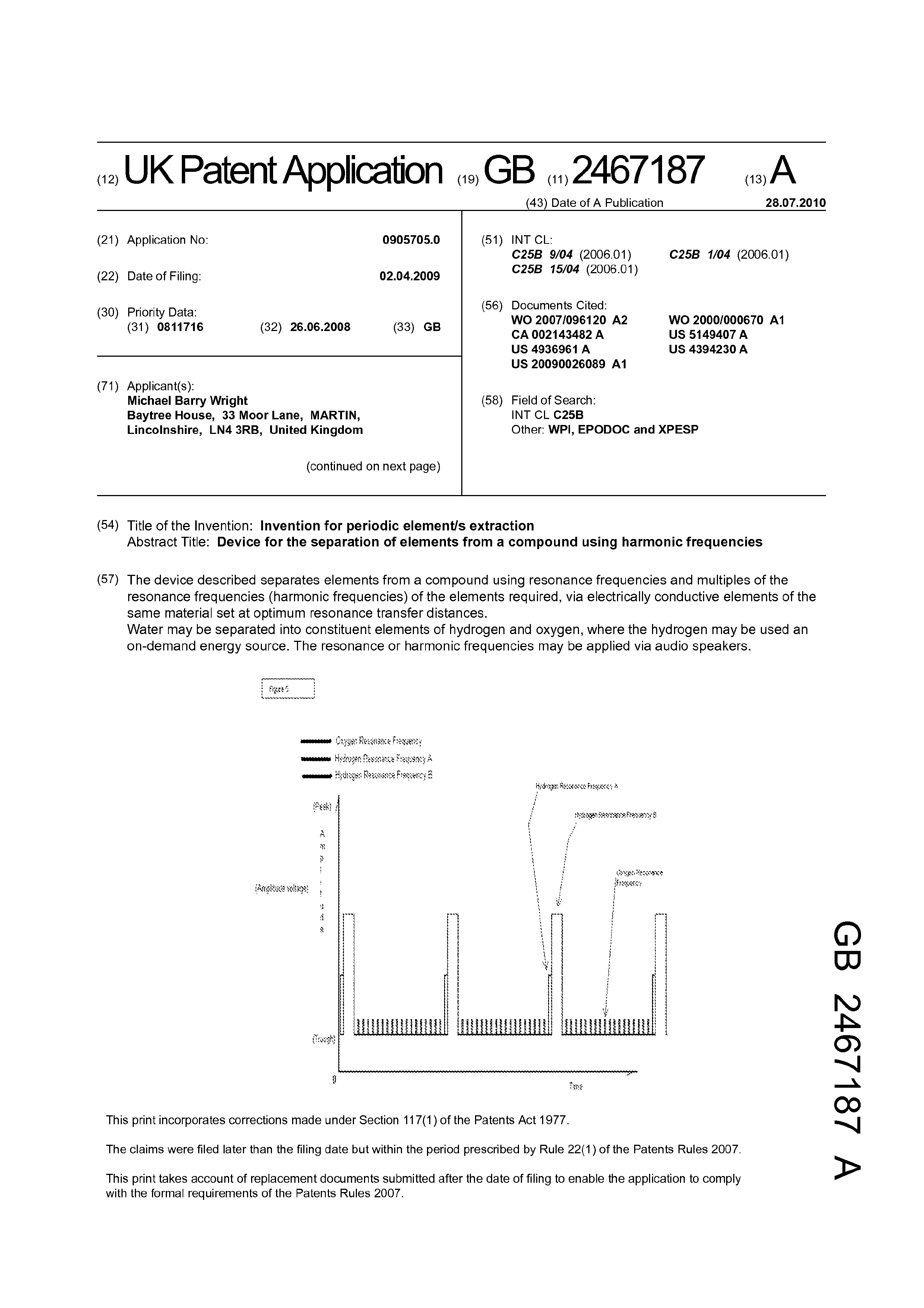
Figure §
Time
Page 8
Drawing sheet — no readable text.
Page 9
Drawing sheet — no readable text.
Page 10
NTT Pe
AN p (— 0” PREASIRE a oO | 7 REGULATORAND
0 (6A FLASHBACK POT
panne a ELEMENT Bt iwitat PP" e—_e co fEIRC FL) 5
OleMALS ty ie] :
Kab a t i fa i
/ miuih ine |
EDI lie | — ike
II, _—- CONDUCTIVE
THT Wiehe PLATES p43}
OPS,
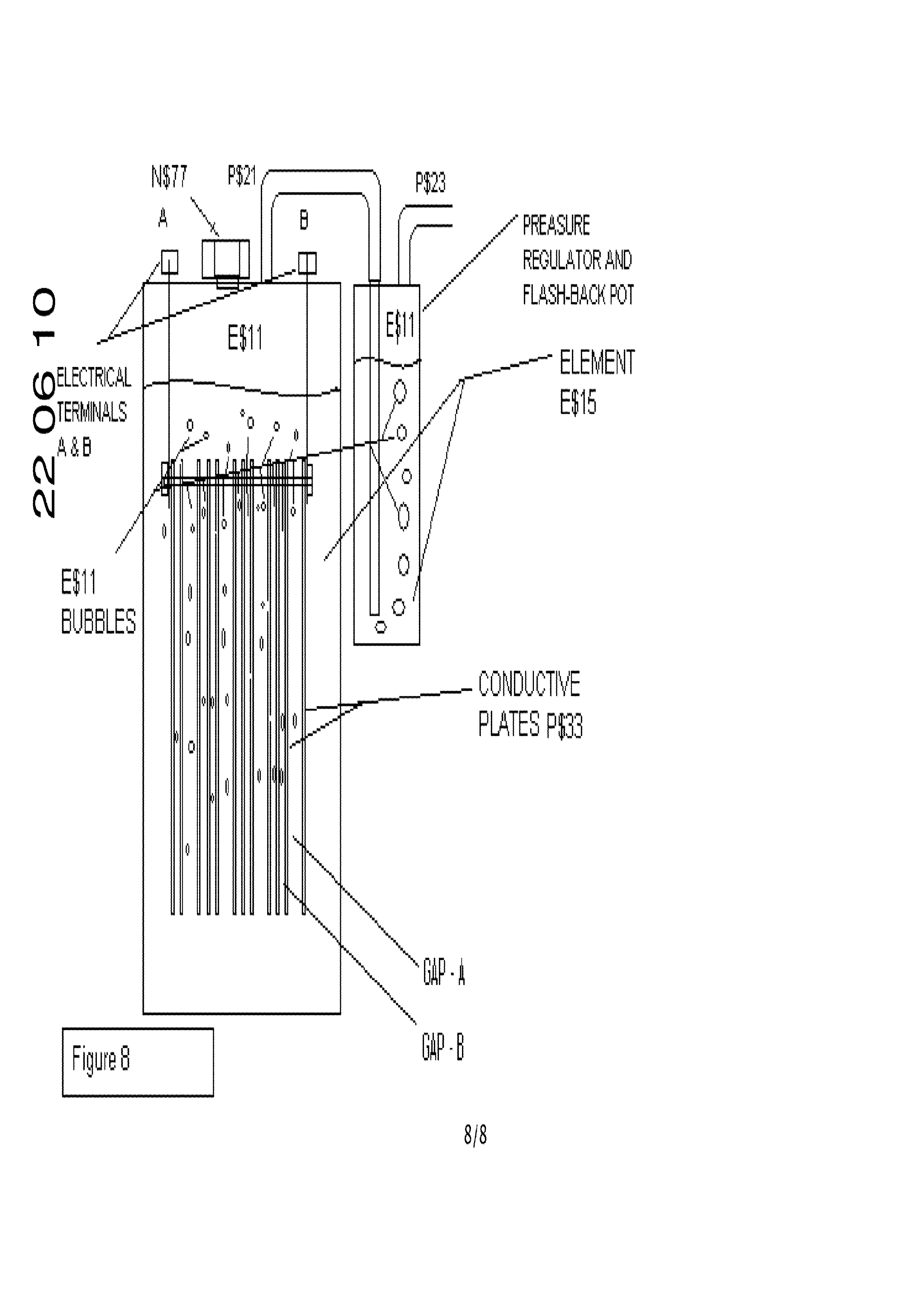
Figure 8 WE
Page 11
1 Description Overview
To separate the constituent components from a compound in liquid form; in this worked example to separate the desired components /elements hydrogen and oxygen from water in an efficient manner, through an economical extraction process, to then be able to use the hydrogen and oxygen as a green energy source, thus allowing for the safe storage of hydrogen in water and only separating it upon demand.
The separation of components/elements from a liquid compound (in the worked example instance H20 (water)) by using the resonance frequencies and harmonics of the resonance frequencies of the desired components /elements to be extracted from the liquid compound. Included can also be the resonance frequency of the liquid compound at a low amplitude in conjunction with the components/elements harmonic frequencies. (Amplitude, being a voltage and as the amplitude increases so does the voltage).
It is known that not all a compounds in liquid form such as Metal ore or water (H20) are pure and thus in this example a process is required to be able to extract the hydrogen and oxygen from water and this includes ordinary tap water and the knowledge of the impurity of the source compound is used to an advantage to assist with the harmonic resonance separation process; in an energy efficient manner, which is what this patent does.
The worked example shows the use of electrical plates delivering the resonance and harmonics of the resonance frequencies but is also understood that the desired results can be achieved by using and delivering the resonance and harmonic frequencies of the desired constituent compounds to be extracted acoustically, this is by means of sending the resonance and resonance harmonics as audio waves through speaker, this principal is included in this patent.
The worked example is based on the understanding that if used in a specific compound extraction of Oxygen and Hydrogen from water (H20) then it would be considered that this invention is based on the extracting of elements (namely, Hydrogen and oxygen) from compounds (namely, water (H20)) by using the resonance frequencies and multiples of the resonance frequencies (harmonic frequencies) of the desired elements and compound, along with a combination of harmonic frequencies of other elements making up the compound being passed through electrodes of the same material submerged in the compound and being spaced so as to set a best resonance transfer distances to optimize the extraction of the elements gasses.
Page 12
2 Applications,
There are numerous applications of this method of extraction from metal ore refinement to the efficient extraction of hydrogen and oxygen from water. There are ways to use the beneficial hydrogen energy once the hydrogen has been extracted in a safe efficient manner from a source liquid compound, detailed are some of the options along with one of the initial and included in this patent options to supplement existing fuel systems with the hydrogen supplementing the primary fuel and complimenting it in doing so, allowing for a dual fuel system and in so doing extending the original fuels life expectancy.
e Inacombustion engine as a combined source of energy, used as a dual fuel by burning both hydrogen and the vehicles designated/original fuel (gasoline, diesel, ethanol, methanol and petrol to name a few).
e Asthe sole source of fuel for a combustion engine or combustion energy source. e As the hydrogen and oxygen source feed for a hydrogen fuel cell.
The resonance frequency is generated using a non-sinusoidal waveform (Non-sinusoidal waveforms are waveforms that are not pure sine waves. They are usually derived from simple math functions. While a pure sine consists of a single frequency, non-sinusoidal waveforms can be described as containing multiple sine waves of different frequencies. These "component" sine waves may, or may not, be multiples of a fundamental or "lowest" frequency. The frequency and amplitude (amplitude, being a voltage and as the amplitude increases so does the voltage) of each component can be found using a mathematical technique known as Fourier analysis.) pulse wave, which is similar to a square wave but rectangular (is commonly referred to as a rectangle wave).
Hydrogen bonds within with oxygen to form water in two ways, para-H20 and orth-H20. It is believed that hydrogen bonds between para-H20, possessing no ground state spin, are stronger and last longer than hydrogen bonds between orth-H20.
Page 13
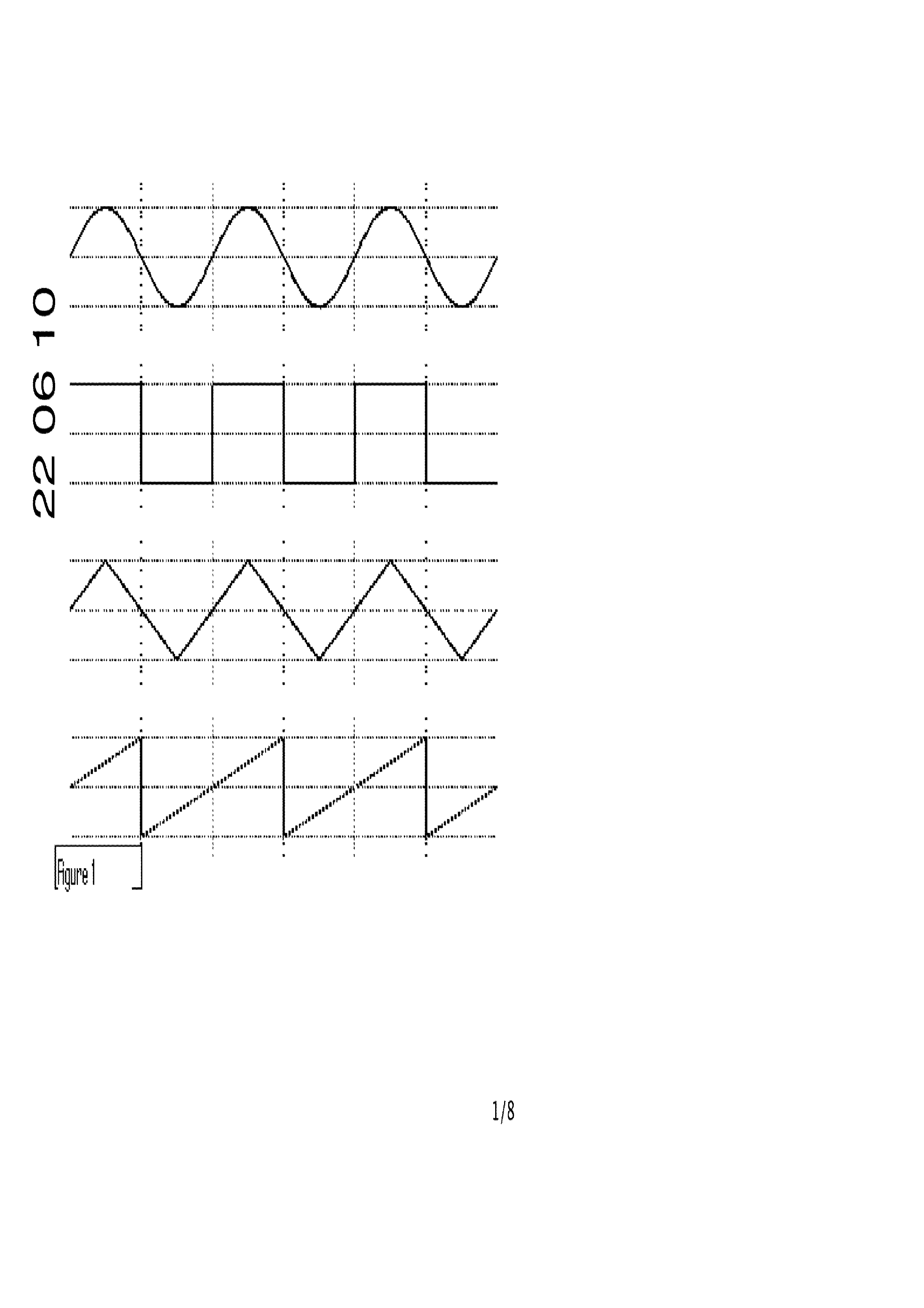
3 Types of waveforms
Sine Wave
Square Wave
Triangular Wave
Saw Tooth Wave
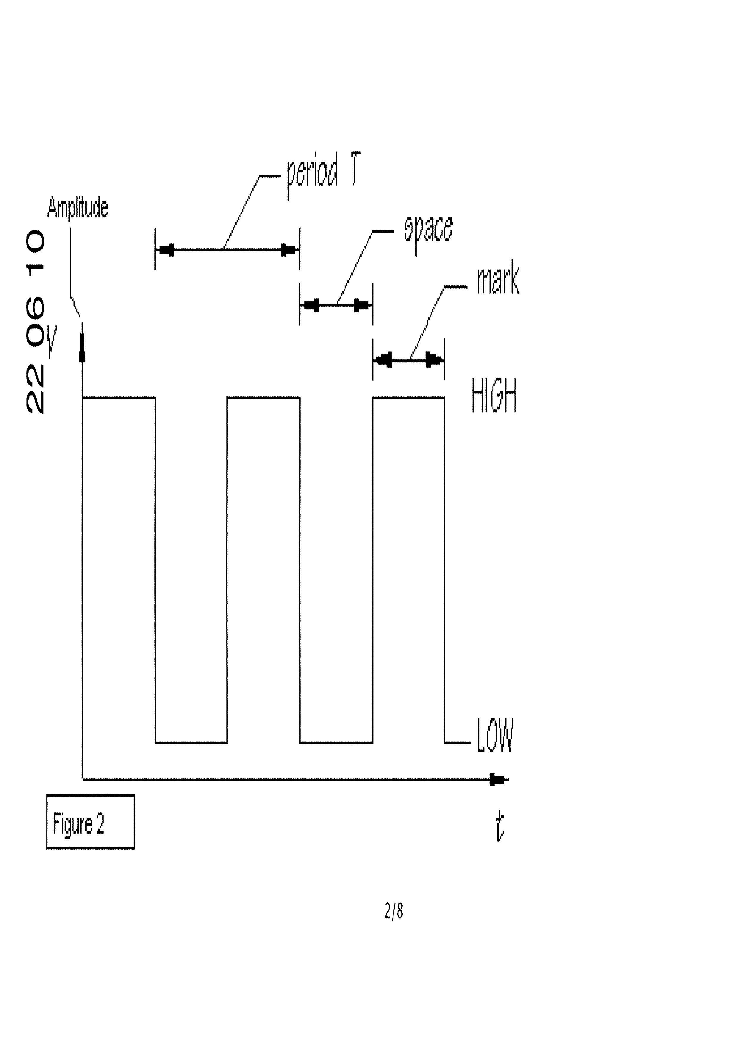
Figure 2 indicates a pulse waveform.
A Pulse wave is similar to a square wave but rectangular (is commonly referred to as a rectangle
wave).
4 Waveforms Used.
As indicated in figure 2; the pulse waveform is used where the space time is greater than the Mark time and the pulse waveform is set at the resonance frequency of the Hydrogen | with an amplitude (amplitude, being a voltage and as the amplitude increases so does the voltage) twice that of the Oxygen resonance frequency waveform.
A further pulse hydrogen resonance waveform is used which is twice the amplitude (amplitude, being a voltage and as the amplitude increases so does the voltage) again of the previous hydrogen resonance frequency waveform. This being the key waveforms resonance signals used to accelerate the hydrogen elements separation from the oxygen.
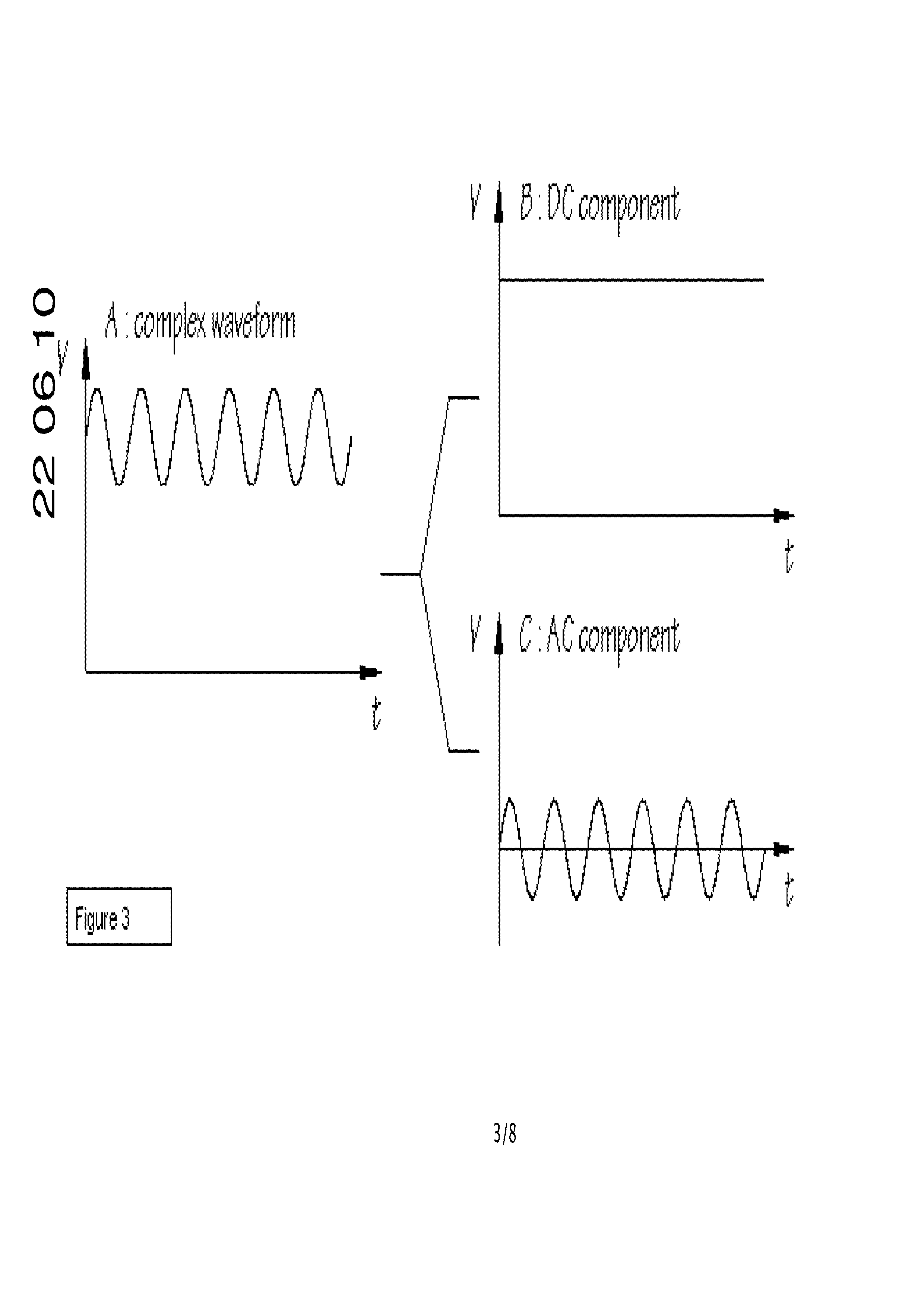
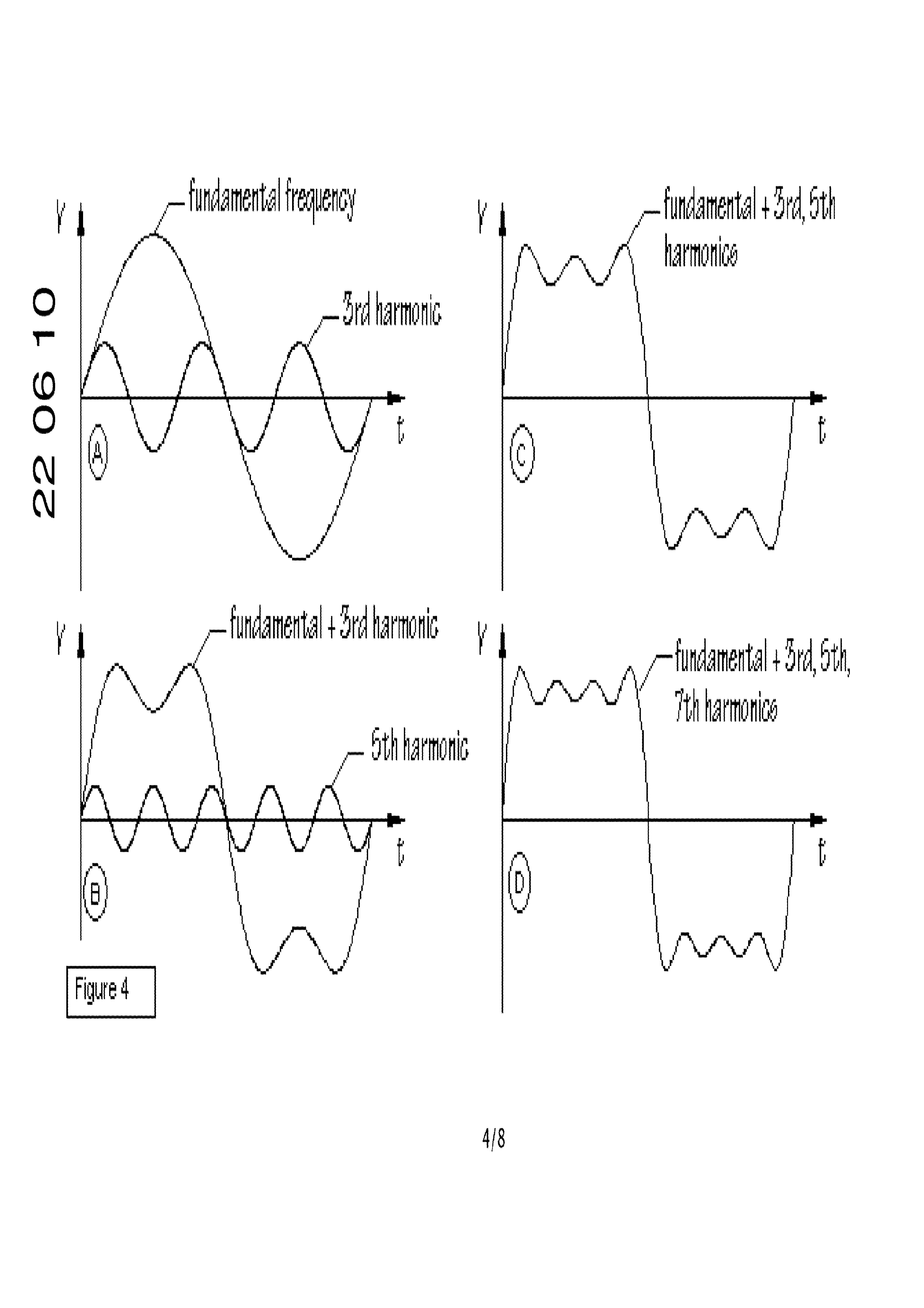
Figure 3 shows the making of a complete wave form from a DC Component and an AC Component and merging them together. The different wave forms (AC Components) and DC components which when merged make a positive floating AC wave form which is the make-up of a complex wave form.
There is a requirement to allow for the effects of added harmonics in the waveform; which is also known as Gibbs phenomenon or ripple effects similar to those of the c-approximation, as indicated
in figure 4.
Figure 3 and figure 4 shows an example in the process used to generate the complex wave form and harmonics which are discussed and used by this process to separate the hydrogen and oxygen from water (H20).
The resonance frequency is generated using a non-sinusoidal waveform (Non-sinusoidal waveforms are waveforms that are not pure sine waves. They are usually derived from simple math functions. While a pure sine consists of a single frequency, non-sinusoidal waveforms can be described as
Page 14
containing multiple sine waves of different frequencies. These "component" sine waves may, or may not, be multiples of a fundamental or "lowest" frequency. The frequency and amplitude (amplitude, being a voltage and as the amplitude increases so does the voltage) of each component can be found using a mathematical technique known as Fourier analysis.)
Hydrogen bonds within with oxygen to form water in two ways, para-H20 and orth-H20. It is believed that hydrogen bonds between para-H2O, possessing no ground state spin, are stronger and last longer than hydrogen bonds between orth-H20.
5 Merged Wave forms
The different wave forms are merged together to create a complex wave form (frequency pattern) signal, were the complex wave form is required to separate the elements hydrogen and oxygen in an energy efficient manner.
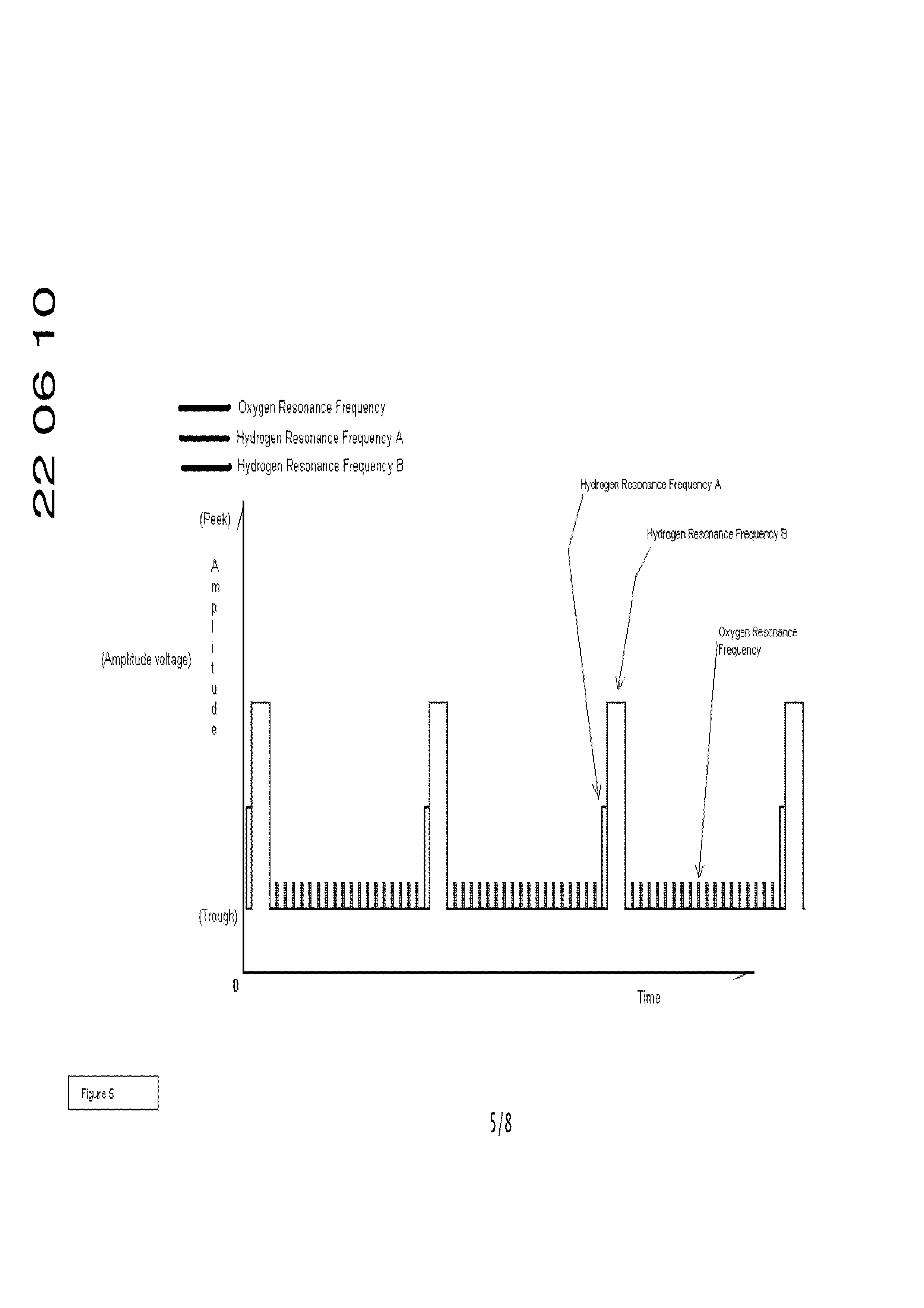
The merging of the DC and AC waveforms to form a complex waveform is used as indicated in figure 5, this complex wave form is used in the process of separating the desired elements (hydrogen (H) and oxygen (O)) from a liquid compound (water (H20) and is one of the fundamental parts of this
patent.
The complex wave form as seen in figure 5 is made of a number of specific waveforms.
e Oxygen resonance frequency, this is a mixture of a pulse and saw tooth wave with a shorter peek amplitude time constant duration than the trough amplitude time constant duration and is set at the resonance frequency of oxygen. The volume generation is controlled by the increasing (for more) or decreasing (for less) of the amplitude.
e Hydrogen resonance frequency A, this is a mixture of a pulse, saw tooth and sine wave with a shorter peek amplitude time constant duration than the trough amplitude time constant duration and is set at the resonance frequency of hydrogen. The volume generation is controlled by the increasing (for more) or decreasing (for less) of the amplitude.
e Hydrogen resonance frequency B, this is a mixture of a pulse, saw tooth and sine wave with a shorter peek amplitude time constant duration than the trough amplitude time constant duration and at a greater peek amplitude and longer peck amplitude time constant than the hydrogen resonance frequency B, and is set at the resonance frequency of hydrogen. The volume generation is controlled by the increasing (for more) or decreasing (for less) of the amplitude.
e Oxygen and hydrogen resonance harmonics are the hydrogen and oxygen harmonic frequencies which are multiples of the hydrogen and oxygen harmonic frequencies and comprise of a mixture of saw tooth, pulse, sine and square waves. The volume generation is
Page 15
controlled by the increasing (for more) or decreasing (for less) of the amplitude in conjunction with the resonance frequency amplitude changes.
The following explains the complex wave form in figure 5.
Throughout the amplitude/s (amplitude, being a voltage and as the amplitude increases so does the voltage) of the hydrogen resonance frequency A and hydrogen resonance frequency B are the additional oxygen and hydrogen resonance harmonics (explanation in figure 4), the harmonic frequencies are multiples of the oxygen and hydrogen resonance frequencies and the harmonics can extend all the way to include the liquid compound's (water) harmonic frequency which is an additional resonance frequency which can be used to further extend the efficiency of the complex wave form of this patent and is included in this patent in it’s ability to be able to extract elements (hydrogen (H) and oxygen (O) of the periodic table) from a liquid compound (water (H20)) in an energy efficient manner.
The hydrogen resonance frequency A is used to start the separation process; which can be in more than one stage to step up to the level of the hydrogen resonance frequency B and the hydrogen resonance frequency B is what executes the separation of the hydrogen from the oxygen.
The hydrogen resonance frequencies are made of the hydrogen and oxygen harmonic frequencies which are extend through the whole amplitude of the hydrogen resonance frequency A and the hydrogen resonance frequency B frequencies of figure 5. Figure 4 shows the harmonic frequency principle and Figure 5 showing the generated complex wave form (frequency pattern) signal used for the hydrogen and oxygen separation from water (H20).
The patent is to include the complete wave form; which is a verity and combination of resonance (resonance frequencies of hydrogen, oxygen and water, though does not have to include water in all separation uses, as this will depend on the absolute energy requirements), harmonics (harmonics of hydrogen, oxygen and water, though does not have to include water in all separation uses, as this will depend on the absolute energy requirements) and frequency wave forms including pulse, saw tooth, sine and square waves to make up the complex wave form (frequency pattern) for the separation of the elements from the liquid compound in this apparatus used and explained is the elements hydrogen and oxygen from the liquid compound of water.
The resonance and harmonic wave forms which make up the complete wave form indicated in figure 5 can all be individually be made from a pulse wave for each resonance and harmonic frequency requirement as indicated in figure 5.
6 Generator Unit
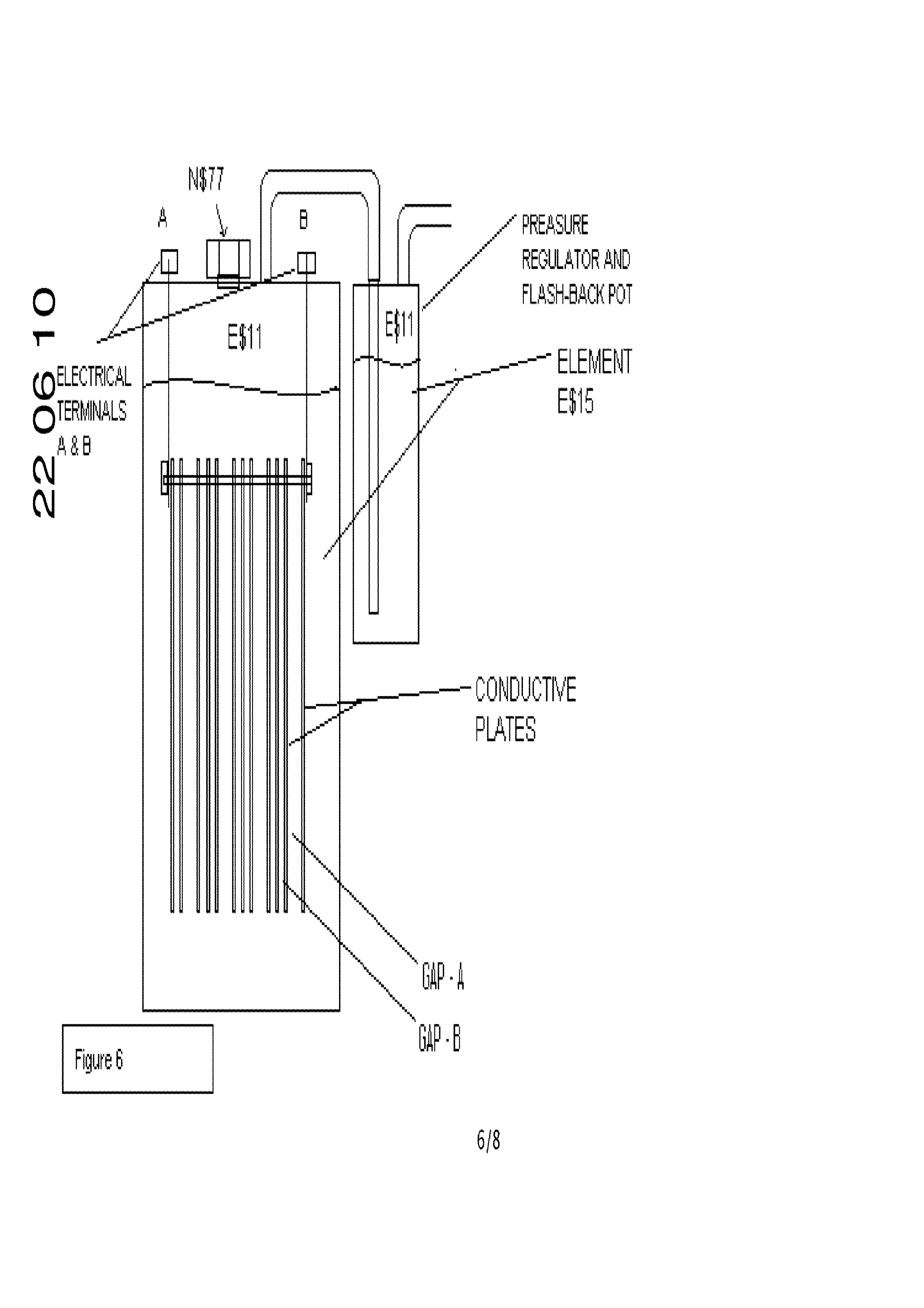
Figure 6 gives an overview of the hydrogen generator assembly ,the container/vessel/pot can be cylindrical as is used in the current apparatus though the can be any shape, so long as they are able
Page 16
to house the conductive plates in the required formations, are sealed accepting for the joining pipes, can house the compound (element ES$15 in figure 6) being separated into hydrogen and oxygen (E$15 in figure 6) and fed through to a second container/vessel/pot as a pressure regulator and flash-back pot.
The re-fill point NS77 of figure 6 is sealed whilst in operation and is remove for the re-filing of the water (H20) to the generator unit.
The generator / separation apparatus unit shown in figure 6 is made of two primary containers/vessels/pots one being the pressure regulator and flash-back pot and the other the main container/vessel/pot is the generator/separator container/vessel/pot (this has the conductive plates in it) each container/vessel/pot is a measured capacity unit container.
The pressure regulator and flash-back pot allows for the extracted gas elements (E$11 of figure 6 / hydrogen and oxygen) to pass through a non flammable and pressure resistant liquid (water/ ES15 of figure 6) to prevent any flame flash-back passing all the way back to the generator /separator pot and also allows for the balancing of the pressure to the engine or device which the hydrogen and oxygen is being generated for (direct to the air intake of a combustion engine).
The Element E$15 of figure 6 is water (H20) this can be tap, bottled, distilled or rain water to detail a few.
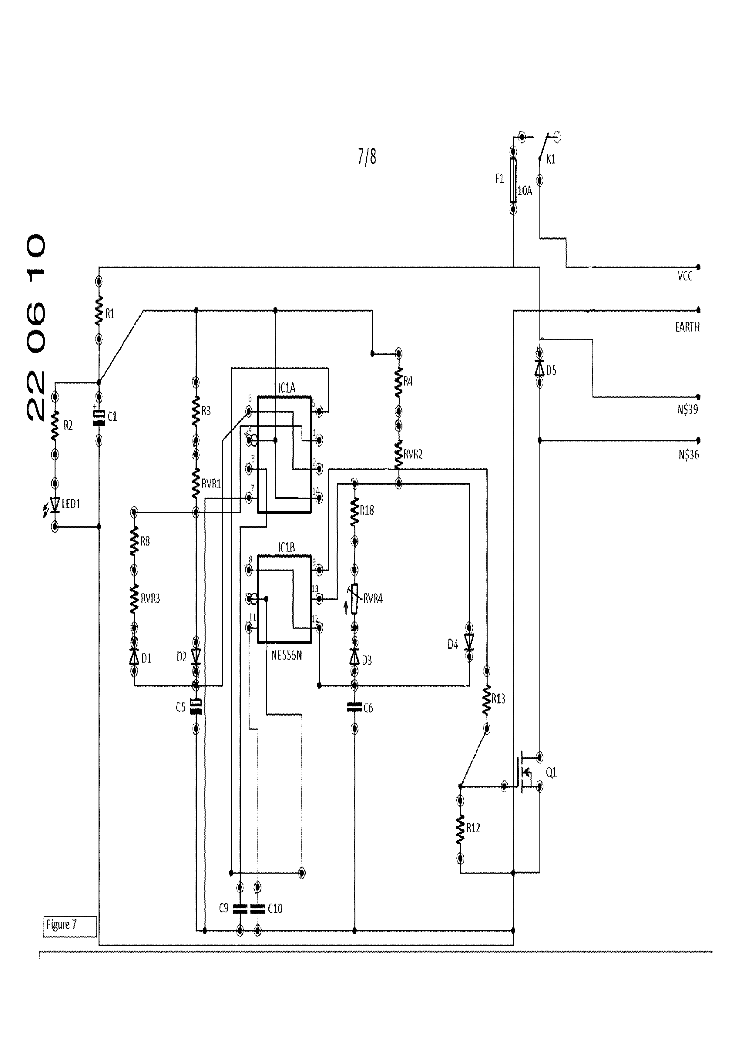
The electrical terminals A & B in figure 6 are connected to the outputs N$39 and N$36 of the electronic circuit of figure 7, which generates the complex wave form signal as shown in figure 5 electrically and is connected to the electrical Terminals A & B of figure 6 which connect to the Conductive plates in figure 6.
7 Conductive plate assembly for generator units
The Conductive Plates of figure 6 are of a single electrically conductive material (all the same) which is resistant to corrosion; currently stainless steel 316L is being used but can be of any other non corrosive or corrosion resistant material like (preferably) titanium or carbon or a carbon alloy and all being of that same material.
The conductive plates are spaced as indicated in the GAP-A and GAP-B of figure 6 for the most efficient transfers of the complex wave form signal frequency pattern as indicated in figure 5 within the solution E$15 being water (H20) in figure 6 to have the periodic elements hydrogen and oxygen through electronic harmonic excitement to be separated from the compound (water).
The plate spacing’s of “GAP-A” and “GAP-B” as indicated in figure 6 are significant to the perspective ratio of hydrogen and oxygen and type of hydrogen, be it orth-H20 or para-H20, being separated through the complex wave form signal as electronic harmonic excitement.
Page 17
8 Circuit diagram
The current economic market dictates the circuit used, the frequency signal pattern as indicated figure 5 is the required outcome of the electronic circuit and so long as the signal pattern is produced, as indicated in figure 5 of section 3; which is a key part to this patent makes the ability to split the hydrogen and oxygen elements from the liquid compound, which in the current apparatus used is water (H20) in an efficient manner requiring a lot less energy than what is nominally required in suppuration of hydration and oxygen from water (H20) in standard electrolysis and mixed metal liquid compound apparatus.
The circuit diagram figure 7 is based on a DC supply connecting positive voltage to VCC and negative voltage to EARTH of figure 7.
Figure 7 is the electronic circuit used to generate the complex wave form used for the low energy separation of hydrogen and oxygen from water. This circuit is in no way fixed, as the requirement is to be able to generate the desired resonant frequencies as detailed section 5 of the Merged Wave Forms and Figure 5.
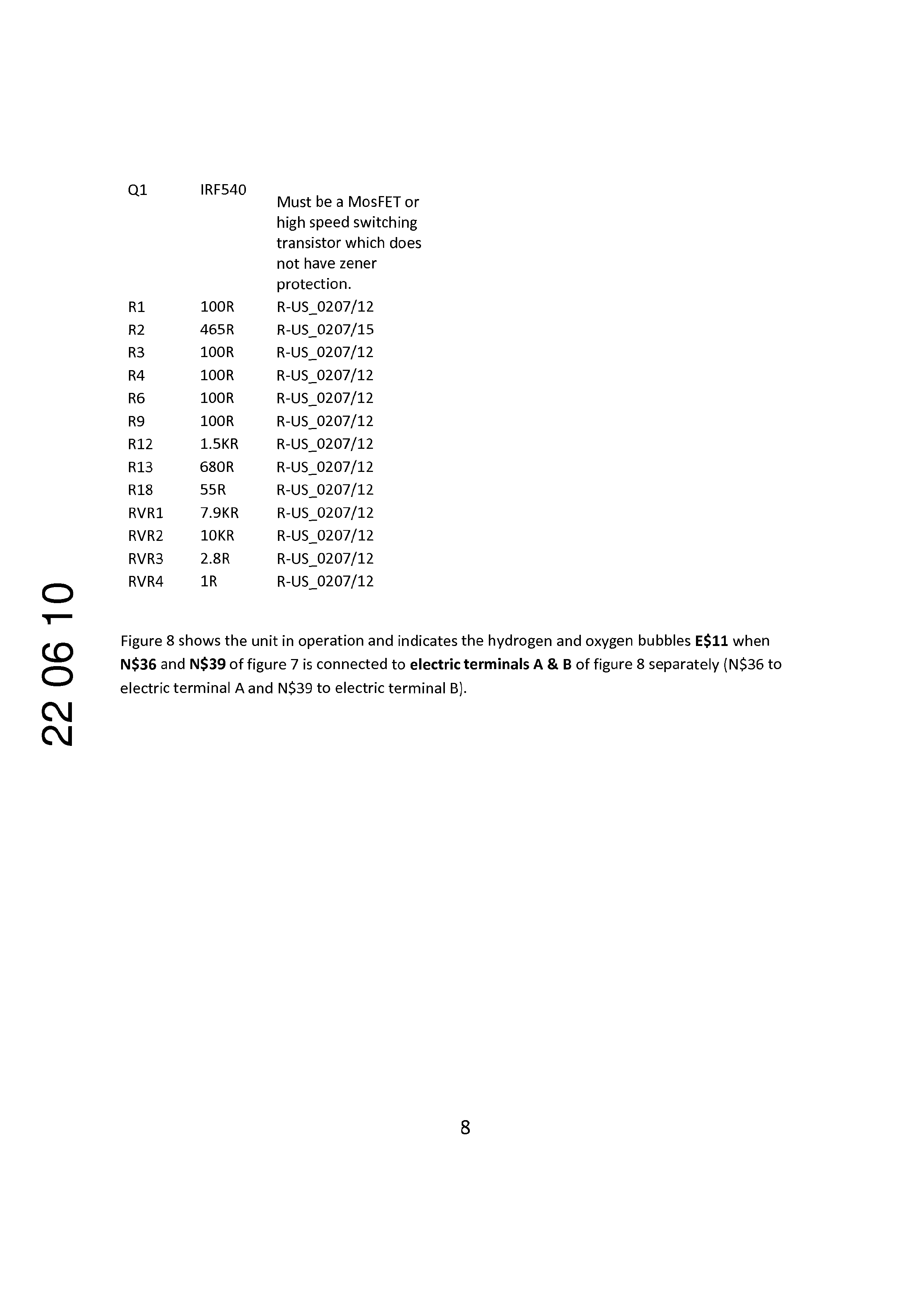
Below is a list of the components used in figure 7. The main driving MosFET (Q1) of figure 7) is not able to be a protected device like a BUZ71 as the protection zener diode causes failings in the ability to deliver the low amplitude harmonics.
Part Value Device
LED1 REDLED LED3MM
Page 18
Must be a MosFET or
high speed switching transistor which does not have zener
protection.
Figure 8 shows the unit in operation and indicates the hydrogen and oxygen bubbles E$11 when
CO N$36 and NS39 of figure 7 is connected to electric terminals A & B of figure 8 separately (N$36 to ) electric terminal A and N$39 to electric terminal B).
Page 19
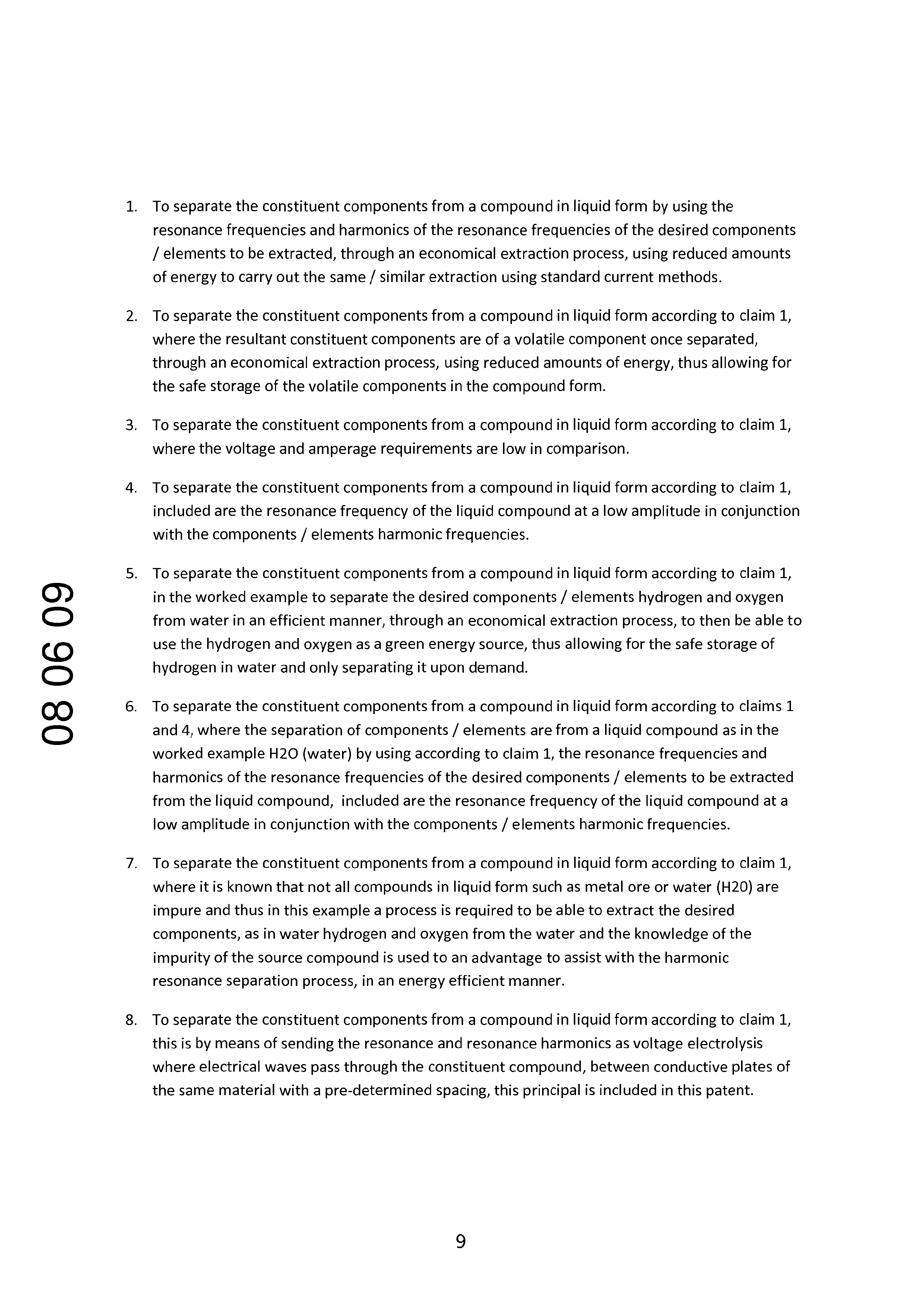
To separate the constituent components from a compound in liquid form by using the resonance frequencies and harmonics of the resonance frequencies of the desired components / elements to be extracted, through an economical extraction process, using reduced amounts of energy to carry out the same / similar extraction using standard current methods.
To separate the constituent components from a compound in liquid form according to claim 1, where the resultant constituent components are of a volatile component once separated, through an economical extraction process, using reduced amounts of energy, thus allowing for the safe storage of the volatile components in the compound form.
To separate the constituent components from a compound in liquid form according to claim 1, where the voltage and amperage requirements are low in comparison.
To separate the constituent components from a compound in liquid form according to claim 1, included are the resonance frequency of the liquid compound at a low amplitude in conjunction with the components / elements harmonic frequencies.
To separate the constituent components from a compound in liquid form according to claim 1, in the worked example to separate the desired components / elements hydrogen and oxygen from water in an efficient manner, through an economical extraction process, to then be able to use the hydrogen and oxygen as a green energy source, thus allowing for the safe storage of hydrogen in water and only separating it upon demand.
To separate the constituent components from a compound in liquid form according to claims 1 and 4, where the separation of components / elements are from a liquid compound as in the worked example H20 (water) by using according to claim 1, the resonance frequencies and harmonics of the resonance frequencies of the desired components / elements to be extracted from the liquid compound, included are the resonance frequency of the liquid compound at a low amplitude in conjunction with the components / elements harmonic frequencies.
To separate the constituent components from a compound in liquid form according to claim 1, where it is known that not all compounds in liquid form such as metal ore or water (H20) are impure and thus in this example a process is required to be able to extract the desired components, as in water hydrogen and oxygen from the water and the knowledge of the impurity of the source compound is used to an advantage to assist with the harmonic resonance separation process, in an energy efficient manner.
To separate the constituent components from a compound in liquid form according to claim 1, this is by means of sending the resonance and resonance harmonics as voltage electrolysis where electrical waves pass through the constituent compound, between conductive plates of the same material with a pre-determined spacing, this principal is included in this patent.
Page 20
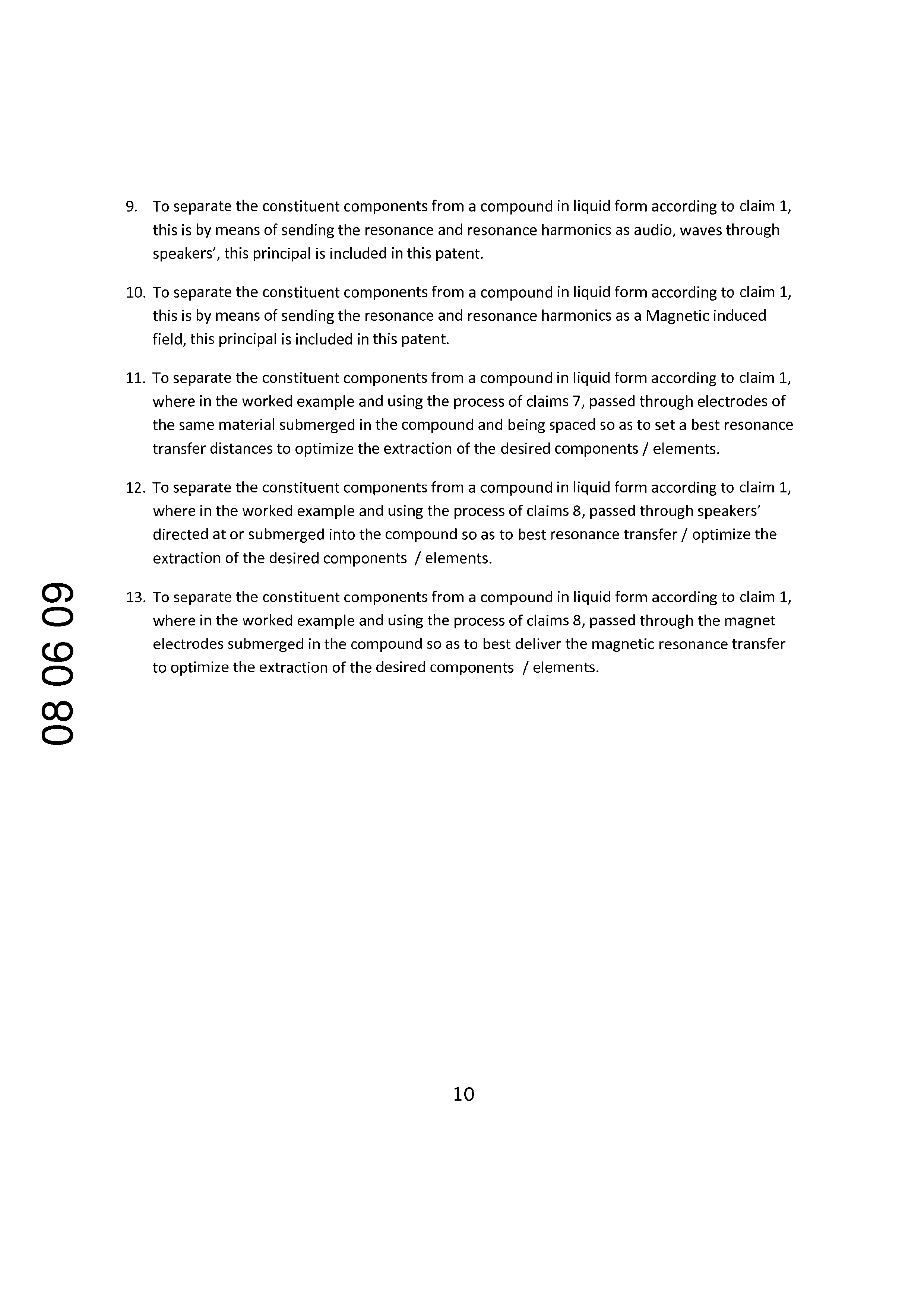
To separate the constituent components from a compound in liquid form according to claim 1, this is by means of sending the resonance and resonance harmonics as audio, waves through speakers’, this principal is included in this patent.
To separate the constituent components from a compound in liquid form according to claim 1, this is by means of sending the resonance and resonance harmonics as a Magnetic induced field, this principal is included in this patent.
To separate the constituent components from a compound in liquid form according to claim 1, where in the worked example and using the process of claims 7, passed through electrodes of the same material submerged in the compound and being spaced so as to set a best resonance transfer distances to optimize the extraction of the desired components / elements.
To separate the constituent components from a compound in liquid form according to claim 1, where in the worked example and using the process of claims 8, passed through speakers’ directed at or submerged into the compound so as to best resonance transfer / optimize the extraction of the desired components / elements.
To separate the constituent components from a compound in liquid form according to claim 1, where in the worked example and using the process of claims 8, passed through the magnet electrodes submerged in the compound so as to best deliver the magnetic resonance transfer to optimize the extraction of the desired components / elements.
Page 21
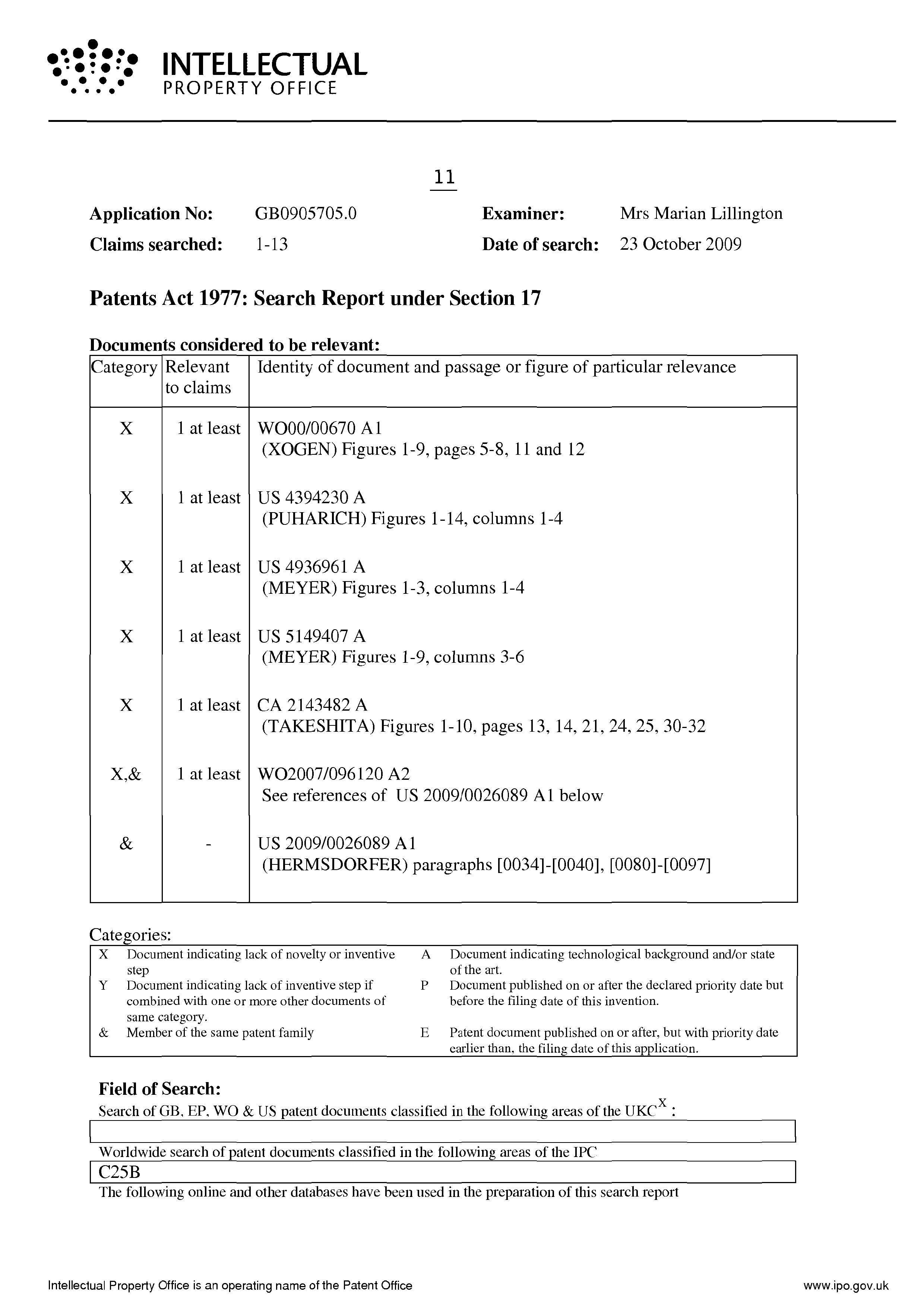
ef? INTELLECTUAL
arn he PROPERTY OFFICE
Application No:
Claims searched:
GB0905705.0 Examiner: Mrs Marian Lillington 1-13 Date of search: 23 October 2009
Patents Act 1977: Search Report under Section 17
Documents considered to be relevant:
Category|Relevant | Identity of document and passage or figure of particular relevance to claims
(PUHARICH) Figures 1-14, columns 1-4
(MEYER) Figures 1-3, columns 1-4
(MEYER) Figures 1-9, columns 3-6
See references of US 2009/0026089 A1 below
Categories:
X Document indicating lack of novelty or inventive A Document indicating technological background and/or state step of the art.
Y Document indicating lack of inventive step if P Document published on or after the declared priority date but combined with one or more other documents of before the filing date of this invention. same category.
& Member of the same patent family E Patent document published on or after, but with priority date
earlier than, the filing date of this application.
Field of Search:
Search of GB, EP, WO & US patent documents classified in the following areas of the UKC x :
Worldwide search of patent documents classified in the following areas of the IPC
The following online and other databases have been used in the preparation of this search report
Intellectual Property Office is an operating name of the Patent Office
Page 22
ef? INTELLECTUAL arn he PROPERTY OFFICE
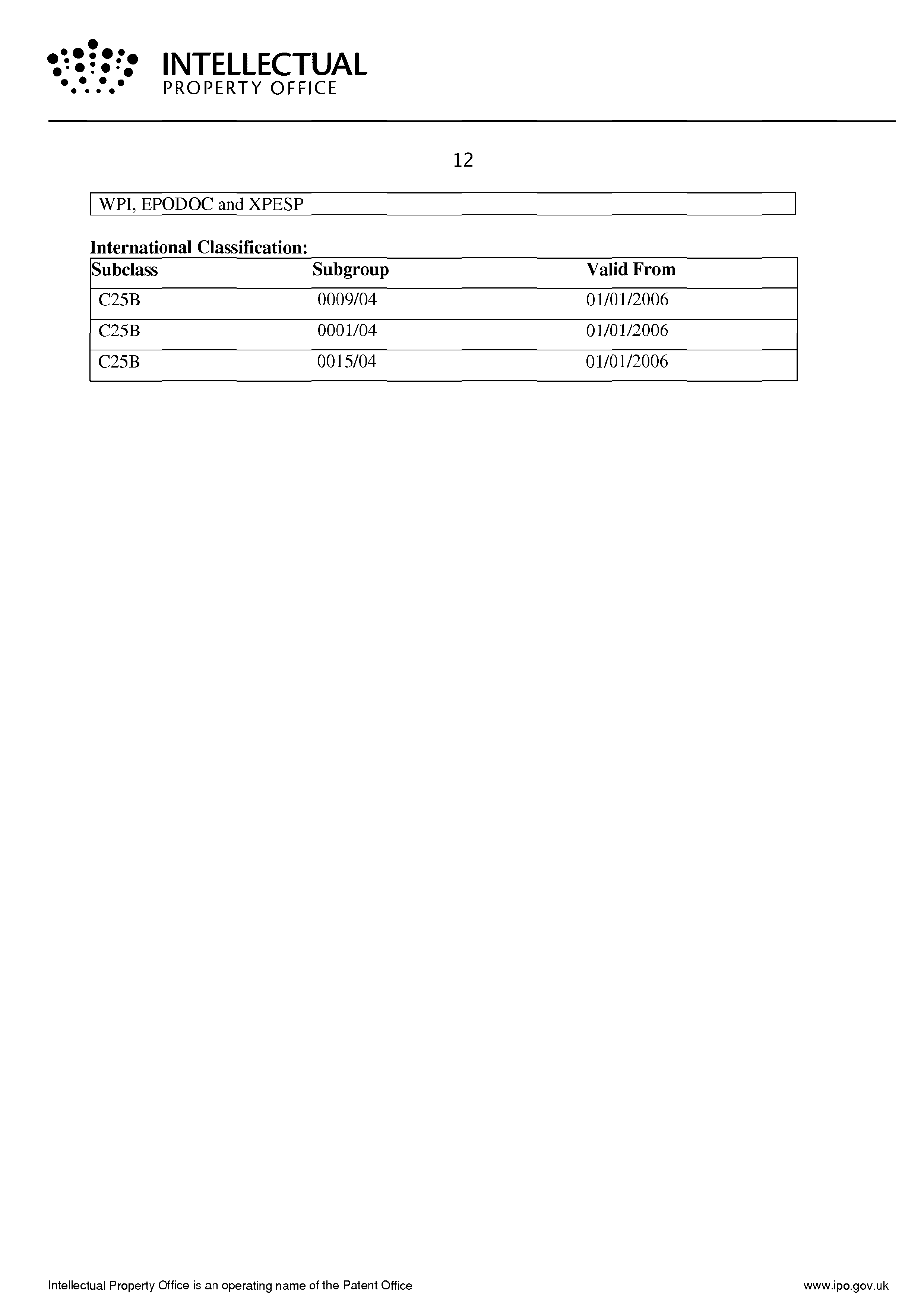
| WPI, EPODOC and XPESP International Classification: Subclass Subgroup Valid From
Intellectual Property Office is an operating name of the Patent Office
Provenance
- Collection
- Patents citing this work
- Pages
- 22
- Method
- pdftoppm 300dpi + tesseract 5 (eng)
- Patent office record
- patents.google.com →
- Source
- Google Patents citing-documents table
- Assignee
- Michael Barry Wright
- Inventors
- Michael Barry Wright
- Published
- 2010-07-28
- Transcribed from
- patentimages.storage.googleapis.com →