patent · GB2324307A
Fracture cell apparatus
21 October 1998
Page 1
UK Patent Application GB «12324307 uA
Christopher Robert Eccles
Westgate House, Dedham, COLCHESTER, Essex,
C07 6H7, United Kingdom
Christopher John Davies
Westgate House, Dedham, COLCHESTER, Essex, (58)
CO7 6H7, United Kingdom
Caroline Jane Davies
Westgate House, Dedham, COLCHESTER, Essex,
CO7 6HJ, United Kingdom
Christopher Robert Eccles
(74) Agent and/or Address for Service
JY & G W Johnson
Kingsbourne House, 229-231 High Holborn, LONDON,
WC1V 7DP, United Kingdom
(51) INT CLé
(52) UK CL (Edition P)
{56) Documents Cited
Field of Search
UK CL (Edition 0) B1X, C1A AK5 , C7B BDAA BDAD
BDAF BDAJ BDAL BDBA 8DBB BDBC
Online: WPI
(54) Abstract Title
Fracture cell apparatus
(57) Fracture cell apparatus including a capacitive fracture cell (20) comprising a container (21) having walls (21a, 21b) made of non-electricaliy conducting material for containing a livid dielectric (26), and spaced apart electrode means (22, 23) positioned outside the container (21) with the liquid dielectric (26) between the electrode means, and means (8a,8b Figs 1, 2) for applying positive and negative voltage pulses to each of the electrode means (22, 23). In use, whenever one of a positive voltage pulse and a negative voltage pulse is applied to one of the two electrode means, the other of a positive voltage pulse and a negative voltage pulse is applied to the other of the two electrode means, thereby creating an alternating electric field across the liquid dielectric to cause fracture of the liquid dielectric (26). The apparatus may be used for generating hydrogen.
FIG. 4
+ve 25hV 2 f ove Z5RV
Phase 2 (zF 7] 0 Phase |
Wott TT T2 iv
ieee \ @ ala WY Te a OO
Amerie Le ’
PAA (! OO
04 Cedi NM & aD | Raat NA
See
ove 25RV YL t ‘)
Phase! TITI IT TA Phase? S
At least one drawing originally filed was informal and the print reproduced here is taken from a later filed formal copy.
Page 2
Drawing sheet — no readable text.
Page 3
Drawing sheet — no readable text.
Page 4
Drawing sheet — no readable text.
Page 5
rae
af \_ = owas ee ee a a a ae
Pea payee
PPE EEE gy
Own J
fy, “ye tud, tay tip
PEE EEE EET
Hi! iy ty bida dy
Page 6
Drawing sheet — no readable text.
Page 7
Fracture Cell Apparatus
This invention relates to fracture cell apparatus and to a method of generating fuel gas from such fracture cell apparatus. In particular, but mot exclusively, the invention relates to an apparatus and method for providing
fuel gas from water.
Conventionally, the principal methods of splitting a molecular species into its component atomic constituents have been either purely chemical or purely electrolytic: Purely chemical reactions always involve "third-party" reagents and do not involve the interaction of (1) an applied external electrical influence, and (2) a simple substance. Conventional electrolysis involves the passage of an electric current through a medium (the electrolyte), such current being the product of ion-transits between the electrodes of the cell. When ions are attracted towards either the cathode or the anode of a conventional electrolytic cell, they either receive or donate electrons on contact with the respective electrode. Such electron exchanges constitute the current during electrolysis. It is not possible to effect conventional electrolysis to any useful degree without the passage of this current; it is an @ priori feature of the process.
A number of devices have recently been described which purport to effect "fracture" of, particularly, water by means of resonant electrostatic phenomena. In particular one known device and process for producing oxygen and hydrogen from water is disclosed in US-A-4936961. In this known device a so-called fuel cell water "capacitor" is provided in which two concentrically arranged spaced apart "Capacitor" plates are positioned in a container of water, the water contacting, and serving as the dielectric between, the "capacitor" plates. The "capacitor" is in effect a charge-dependent resistor which begins to conduct after a small displacement current begins to flow. The “capacitor
forms part of a resonant charging circuit that includes an
Page 8
inductance in series with the "capacitor". The "capacitor" is subjected to a pulsating, unipolar electric charging voltage which subjects the water molecules within the "capacitor" to a pulsating electric field between the capacitor plates. The "capacitor" remains charged during the application of the pulsating charging voltage causing the covalent electrical bonding of the hydrogen and oxygen atoms within the water molecules to become destabilised, resulting in hydrogen and oxygen atoms being liberated from
the molecules as elemental gases.
Such known fracture devices have, hitherto, alwavs featured, as part of their characteristics, the physical contact of a set of electrodes with the water, or other medium to be fractured. The primary method for limiting current flow through the cell is the provision of a highimpedance power supply network, and the heavy reliance on the time-domain performance of the ions within the water (or other medium), the applied voltage being effectively "switched off" in each cycle before ion-transit can occur to
any significant degree.
In use of such a known system, there is obviously an upper limit to the number of ion-migrations, electroncaptures, and consequent molecule-to-atom disruptions which can occur during any given momentary application of an external voltage. In order to perform effectively, such devices require sophisticated current-limiting and very
precise switching mechanisms.
A common characteristic of all such known fracture devices described above, which causes them to behave as though they were conventional electrolysis cells at some point in time after the application of the external voltage, is that they have electrodes in actual contact with the
water or other medium.
Page 9
The present invention seeks to provide an alternative method of producing fracture of certain simple molecular
species, for example water.
According to one aspect of the present invention there is provided fracture cell apparatus including a capacitive fracture cell comprising a container having walls made of non-electrically conducting material for containing a liquid dielectric, and spaced apart electrode means positioned outside the container with the liquid dielectric between the electrode means, and means for applying positive and negative voltage pulses to each of the electrode means so that, whenever one of a positive voltage pulse and a negative voltage pulse is applied to one of the two electrode means, the other of a positive voltage pulse and a negative voltage pulse is applied to the other of the two electrode means, thereby creating an alternating electric field across the liquid dielectric to cause fracture of the
liquid dielectric.
In apparatus according to the invention the electrode means do not contact the liquid dielectric which is to be fractured or disrupted. The liquid to be fractured is the simple dielectric of a capacitor. No purely ohmic element of conductance exists within the fracture cell and, in use, no current flows due to an ion-carrier mechanism within the cell. The required fracture or disruption of the liquid dielectric is effected by the applied electric field whilst
only a simple displacement current occurs within the cell.
Preferably the liquid dielectric comprises water,
e.g. distilled water, tap water or deuterated water.
Conveniently each electrode means comprises a bipolar
electrode.
Suitably the means for alternately applying positive and negative pulses provides step voltages alternately to
the two electrode means with a short period of time during
Page 10
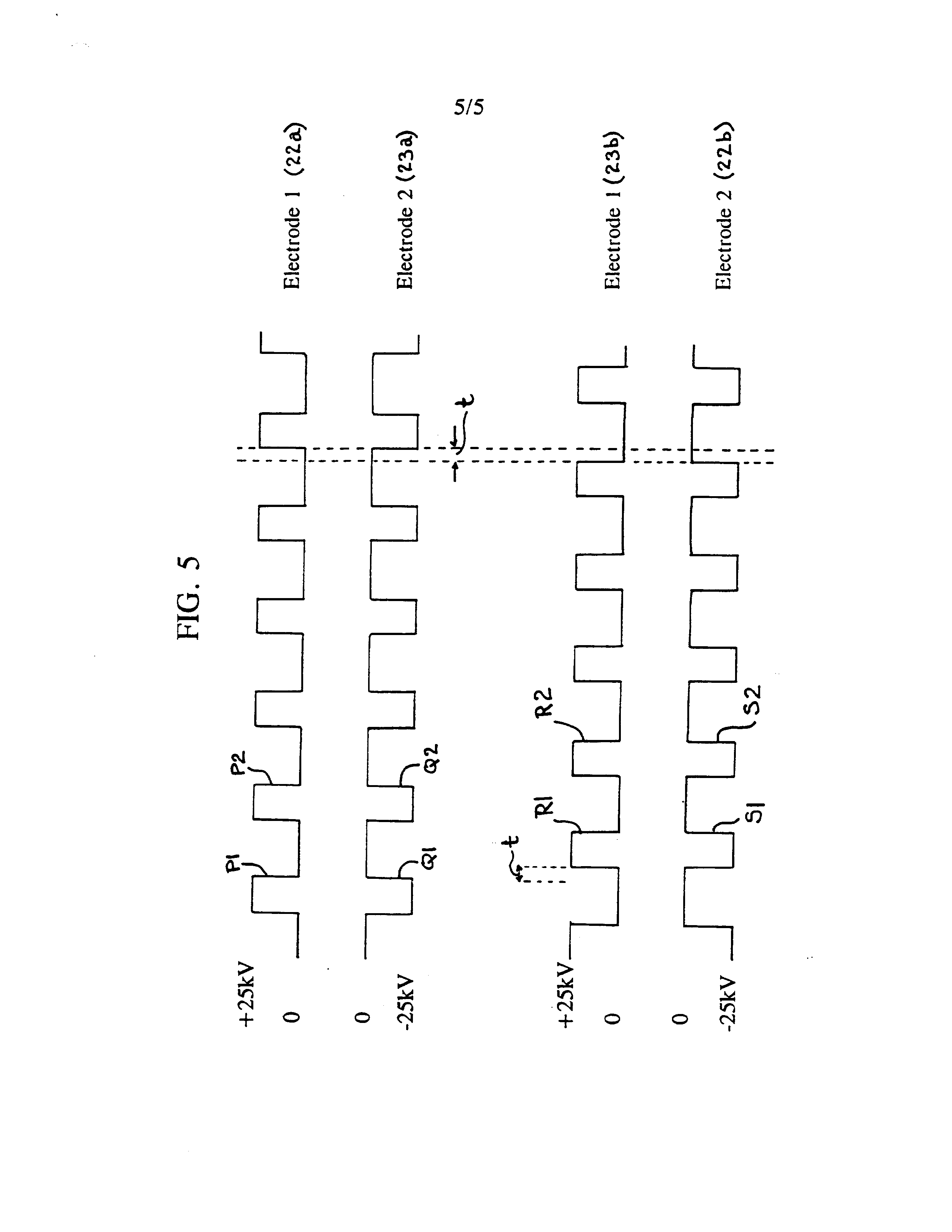
each charge voltage cycle in which no step voltage is applied to either electrode. Typically step voltages in excess of 15 kV, typically about 25 kV, on either side of a reference potential, e.g. earth, are applied to the electrode means. In effect trains of pulses having alternating positive and negative values are applied to the electrode means, the pulses applied to the different electrode means being "phase shifted". In the case where each electrode means comprises a bipolar electrode, each bipolar electrode comprising first and second electrode "plates" electrically insulated from each other, a train of positive pulses is arranged to be applied to one electrode plate of each bipolar electrode and a train of negative pulses is arranged to be applied to the other electrode plate of each bipolar electrode. One electrode plate of one bipolar electrode forms a first set with one electrode plate of the other bipolar electrode and the other electrode plate of the one bipolar electrode forms a second set with the other electrode plate of the other bipolar electrode. For each set, a positive pulse is applied to one electrode plate and a negative pulse is applied simultaneously to the other electrode plate. By alternately switching the application of positive and negative pulses from one to the other set of electrode plates, an "alternating" electric field is generated across the dielectric material contained in the container. The pulse trains are synchronised so that there is a short time interval between the removal of pulses from one electrode plate set and the application of pulses to the
other electrode plate set.
According to another aspect of the present invention there is provided a method of generating gas comprising applying positive and negative voltage pulses alternately to electrode means positioned either side of, but not in contact with, a liquid dielectric, the voltage pulses being applied so that, whenever one of a positive voltage pulse and a negative voltage pulse is applied to one of the two electrode means, the other of a positive voltage pulse and
a negative voltage pulse is applied to the other of the two
Page 11
electrodes means, the applied voltage pulses generating an alternating electric field across the liquid dielectric causing fracture of the liquid dielectric into gaseous
media.
Preferably voltages of at least 15 kV, e.g. 25 kv, either side of a reference value, e.g. earth, are applied across the liquid dielectric to generate the alternating
electric field.
An embodiment of the invention will now be described by way of example only, with particular reference to the
accompanying drawings, in which:
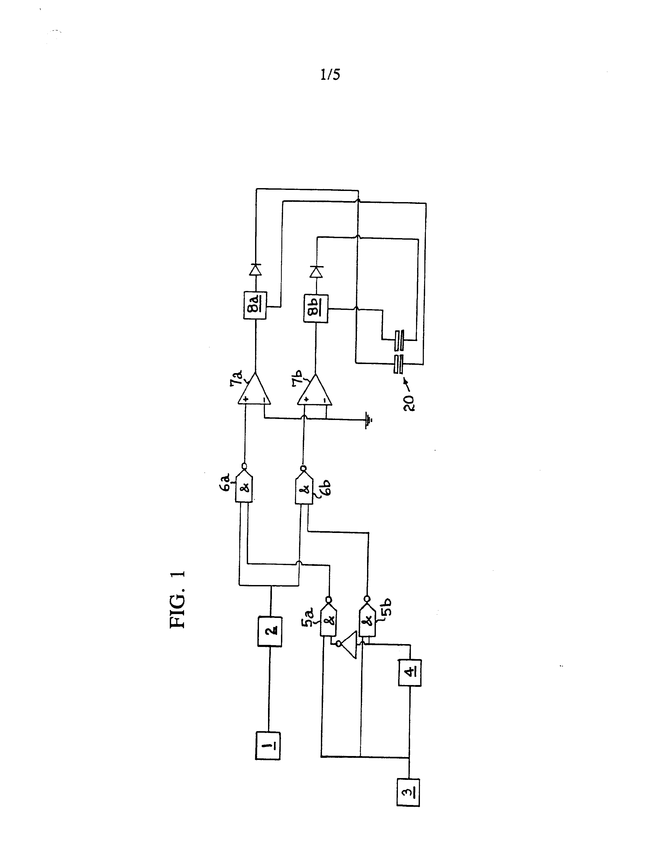
Figure 1 is a circuit diagram of fracture cell
apparatus according to the invention;
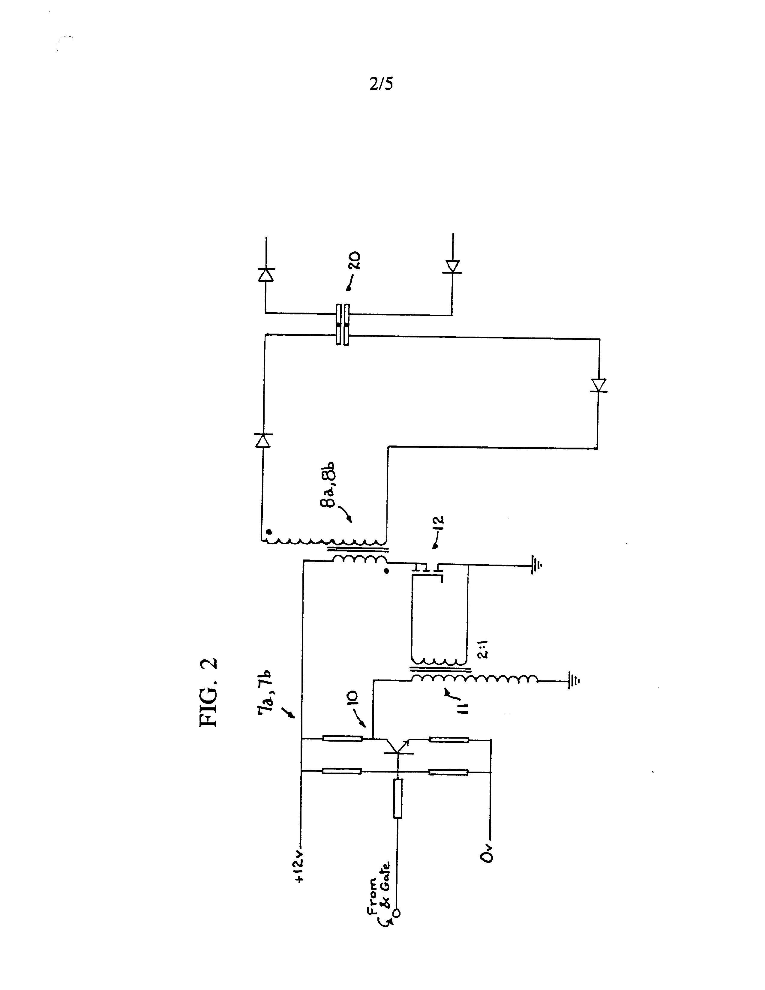
Figure 2 shows in more detail a part of the circuit
diagram of Figure 1;
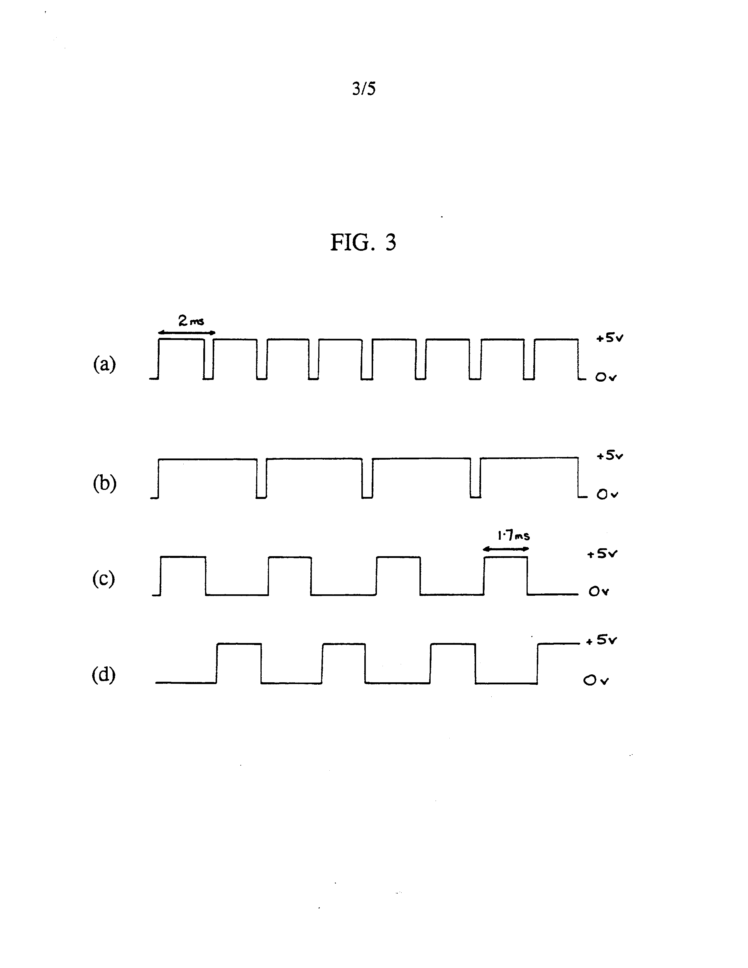
Figures 3a to 3d show different waveforms at various
parts of the circuit diagram of Figure 1;
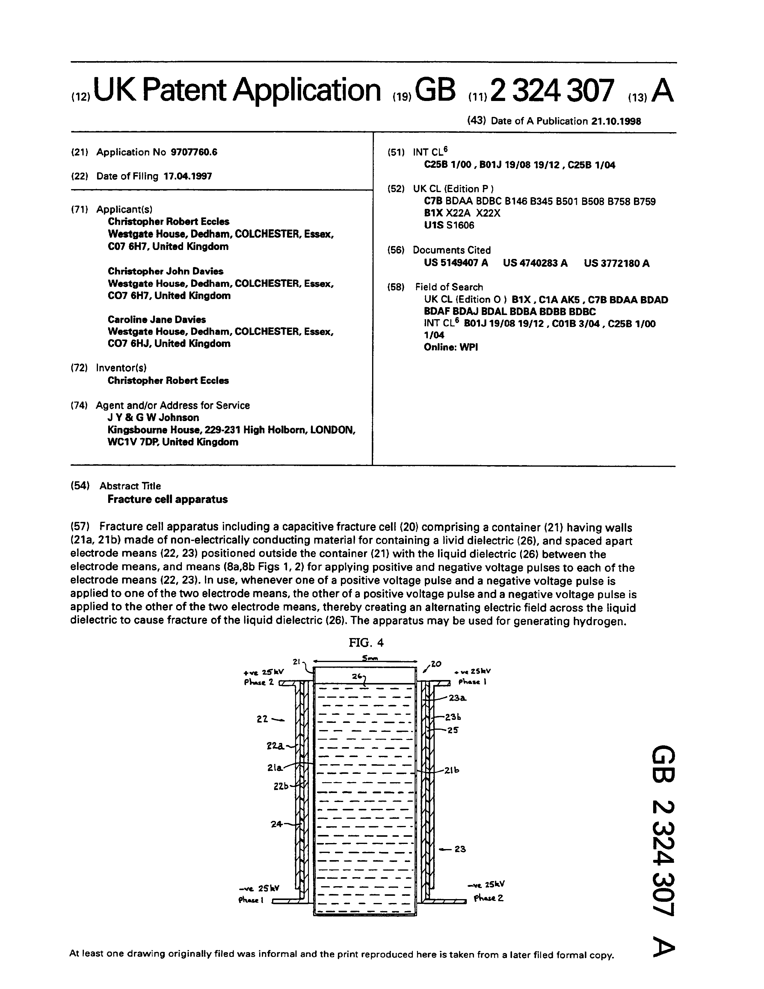
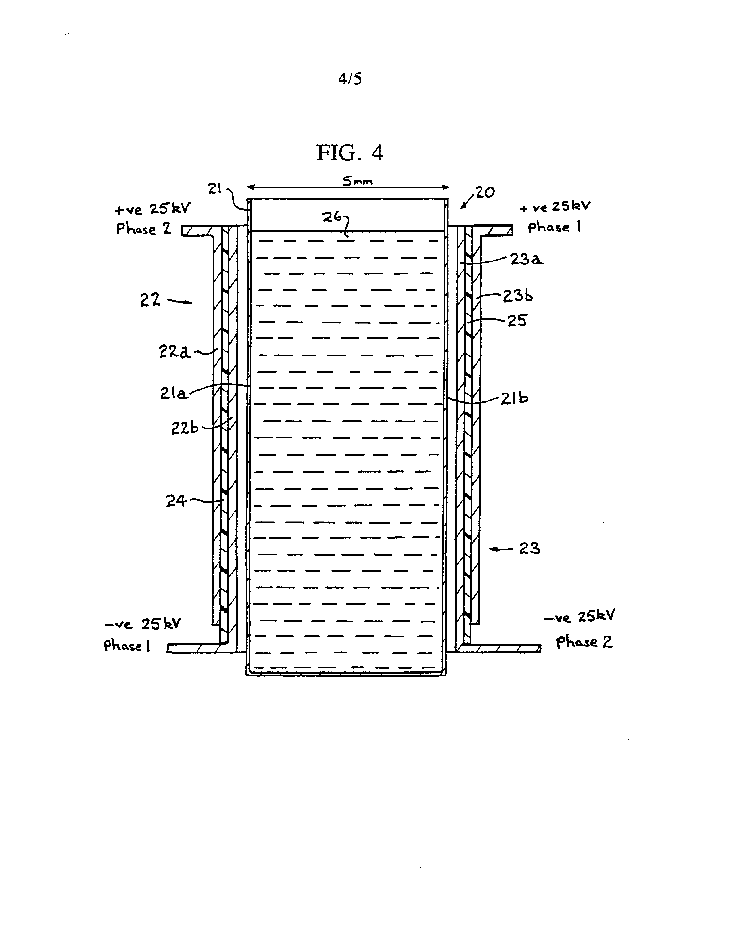
Figure 4 is a schematic diagram of a fracture cell for use in fracture cell apparatus according to the
invention, and
Figure 5 shows trains of pulses applied to electrode means of the fracture cell apparatus according to the
invention.
If a large electric field is applied across a pair of electrode plates positioned either side of a cell containing water, disruption of the water molecules will occur. Such disruption yields hydrogen nuclei and HO~ ions. Such a molecular disruption is of little interest in terms of obtaining a usable result from the cell. A proton-rich zone
exists for as long as the field exists and quickly
Page 12
reestablishes equilibrium ion-product when the field is
removed.
One noticeable side-effect, however, is that the hydroxyl ions (which will migrate to the +ve charged plate) are stripped of electrons as they approach the cell boundary. Any negatively-charged ion will exhibit this behaviour in a strong enough potential well, but the OH™ ions have a strong tendency to such dissociation. This results, momentarily, in a region of negative-charge clese to the positive cell boundary. Thus, on opposite sides of the active cell, there are hydrogen nuclei (free proton zone) and displaced electrons (-ve charge zone), both
tending to increase in density closer to the charged plates.
If, at this point, the charge is removed from the plates, there is a tendency for the charge-zones to move, albeit very slowly, towards the centre of the active cell. The ion-transit rates of free electrons and of hydrogen nuclei are, however, some two orders of magnitude faster
than either H30* ions or OH” ions.
If the charges are now replaced on the plates, but with opposite polarity, the interesting and potentially useful aspect of the process is revealed. Hydrogen nucleus migration is accelerated in the direction of the new -ve plate and free electron migration takes place towards the new +ve plate. Where there is a sufficient concentration of both species, including the accumulations due to previous polarity changes, monatomic hydrogen is formed with the liberation of some heat energy. Normal molecular
association occurs and Hj gas bubbles off from the cell.
Also existing OH” radicals are further stripped of hydrogen nuclei and contribute to the process. Active, nascent O-- ions rapidly lose their electronic space charge to the +ve field and monatomic oxygen forms, forming the diatomic molecule and similarly bubbling off from the cell.
Page 13
Thus, the continuous application of a strong electric
field, changing in polarity every cycle, is sufficient to
disrupt water into its constituent gaseous elements,
utilising a small fraction of the energy required in
conventional electrolysis or chemical energetics, and
yielding heat energy of the enthalpy of formation of the diatomic bonds in the hydrogen and oxygen.
Apparatus for performing the process described above is described below. In particular, electronic circuitry to effect the invention is shown in the simplified block diagram of Figure 1. In Figure 1 a pulse-repetitionfrequency (PRF) generator 1 comprises an astable mvbr clock running at a frequency which is preset for any application, but able to be varied across a range of approximately 5-30 kHz. The generator 1 drives, by triggering with the trailing edge of its waveform, a pulse width (PW) timer 2. The output of the timer 2 is a train of regular pulses whose width is determined by the setting of the timer 2 and whose repetition frequency is set by the PRF generator 1.
A gate clock 3 comprises a simple 555-type circuit which produce a waveform (see Figure 3a) having a period of from 1-5 ms, e.g. 2 ms as shown in Figure 3a. The duty cycle of this waveform is variable from 50% to around 95%. The waveform is applied to one input of each of a pair of AND gates Sa, 5b and also to a binary divide-by-two counter 4.
The output of the counter 4 is shown in Figure 3b.
The signal from the divide-by-two counter 4 is applied directly to the AND gate 5b serving phase-2 driver circuitry 7a but is inverted before application to the AND gate 5a serving phase-1 driver circuitry 7a. The output of the AND gate 5a is therefore ((CLOCK and (NOT (CLOCK) /2)) and the output of the AND gate 5b is ((CLOCK) and (CLOCK/2)), the waveforms, which are applied to pulse-train gates 6a and 6b, being shown at Figures 3c and 3d.
Page 14
Trains of 5-30 kHz pulses are applied to drive amplifiers 7a and 7b alternately, with a small "off"-period during which no pulses are applied to either amplifier. The duration of each "off" period is dependent upon the original duty cycle of the clock timer 3. The reason for the small "off" period in the driver waveforms is to prevent local
corona arc as the phases change over each cycle.
The drive amplifiers 7a, 76 each use a BC182L transistor 10 (see Figure 2), small toroidal 2:1 pulse transformer 11 and a BUZ11 power-MOSFET 12 and apply pulsepackets across primary windings of respective 25 kv lineoutput transformers 8a, 8b to produce an EHT ac voltage of high frequency at the secondary windings. The secondary windings are ‘lifted’ from system ground and provide, after simple half-wave rectification, the applied field for
application to cell 20 (see Figure 4).
The cell 20 comprises a container 21 having walls Z2la, 21b of electrically insulating material, e.g. a thermoplastics material, such as polymethyl methacrylate, typically spaced about 5 mm apart, and bipolar cell electrodes generally designated 22, 23 and typically constructed from aluminium foil, positioned outside the walls 21a and 21b. Each bipolar cell electrode comprises a pair of electrode plates 22a and 22b (or 23a and 23b) for each side of the cell 20 separated from each other by an electrically insulating layer 24 (or 25), e.g. of polycarbonate plastics material about 0.3 mm in thickness. The electrode plates 22a and 23a form one set (set A) of electrode plates positioned on opposite sides of the container 21 and the electrode plates 22b and 23b form another set of electrode plates positioned on opposite sides of the container 21. An insulating layer 25, e.g. of polycarbonate material, similar to the insulating layers 24a or 24b may be positioned between each bipolar cell electrode 22 (23) and its adjacent container wall 21a (21b). A liquid electrolyte, preferably water, is contained in the container
Page 15
In use a train of positive pulses is applied to the electrode plates 22a and 23b and a train of negative pulses is applied to the electrode plates 23a and 22b. The timing of the pulses is shown schematically in Figure 5, which illustrates that, for set A (or for set B), whenever a positive pulse is applied to electrode plate 22a (or 23b), a negative pulse is also applied to electrode plate 23a (or 22b). However the pulses applied to the electrode plate set A are "out of phase" with the pulses applied to the electrode plate set B. In each train of pulses, the duration of each pulse is shorter than the gap between successive pulses. By arranging for the pulses of electrode plate set B to be applied in the periods when no pulses are applied to the electrode plate set B, the situation arises where pairs of pulses are applied successively to the electrode plates of different sets of electrode plates, there being a short interval of time when no pulses are applied between each successive application of pulses to pairs of electrode plates. In other words, looking at Figure 5, pulses Pl and Q1 are applied at the same time to the electrode plates 22a and 23a. The pulses Pl and Ql are of the same pulse length and, at the end of their duration, there is a short time period t before pulses Rl and Sl are applied to the electrode plates 23b and 22b. The pulses Rl and S1 are of the same pulse length as the pulses Pl and Ql and, at the end of their duration, there is a further time t before the next pulses P2 and Q2 are applied to the electrode plates 22a and 23a. It will be appreciated that whenever a pulse of one sign is applied to one of the electrode plates of a set, a pulse of the opposite sign is applied to the other electrode plate of that set. Furthermore by switching from one to the other electrode plate set the polarities applied across the container are repeatedly switched resulting in an "alternating" electric field being created across the "liquid dielectric" water in
the container.
Page 16
CLAIMS
1. Fracture cell apparatus including a capacitive fracture cell comprising a container having walls made of non-electrically conducting material for containing a liquid dielectric, and spaced apart electrode means positioned outside the container with the liquid dielectric between the electrode means, and means for applying positive and negative voltage pulses to each of the electrode means so that, whenever one of a positive voltage pulse and a negative voltage pulse is applied to one of the two electrode means, the other of a positive voltage pulse and a negative voltage pulse is applied to the other of the two electrode means, thereby creating an alternating electric field across the liquid dielectric to cause fracture of the liquid dielectric.
2. Fracture cell apparatus according to claimi, in which the liquid dielectric comprises water.
3. Fracture cell apparatus according to claim i or 2, in which the means for applying positive and negative pulses provides positive and negative step voltages at the same time to each electrode means, the positive and negative step voltages being applied alternately to the two electrode means with a short period of time during each charge voltage cycle in which no step voltage is applied to either
electrode means.
4. Fracture cell apparatus according to any one of the preceding claims, in which each electrode means
comprises a bipolar electrode.
5. Fracture cell apparatus according to claim 4, in which each bipolar electrode comprises first and second plate means, the first plate means of one bipolar electrode and the second plate means of the other bipolar electrode forming one electrode plate set and the second plate means
of said one bipolar electrode and the first plate means of
Page 17
said other bipolar electrode forming another electrode piate set.
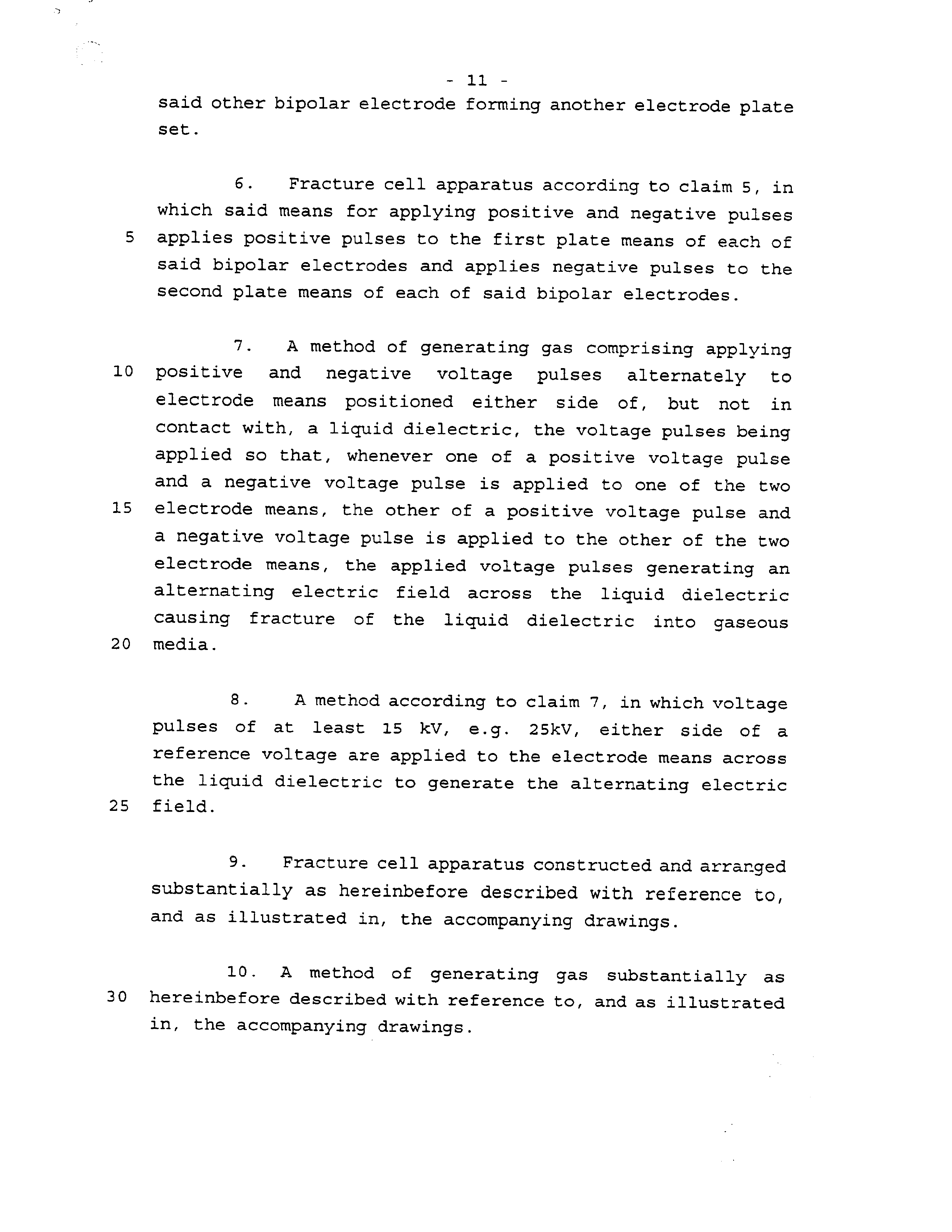
6. Fracture cell apparatus according to claim 5, in which said means for applying positive and negative pulses applies positive pulses to the first plate means of each of said bipolar electrodes and applies negative pulses to the second plate means of each of said bipolar electrodes.
7. A method of generating gas comprising applying positive and negative voltage pulses alternately to electrode means positioned either side of, but not in contact with, a liquid dielectric, the voltage pulses being applied so that, whenever one of a positive voltage pulse and a negative voltage pulse is applied to one of the two electrode means, the other of a positive voltage pulse and a negative voltage pulse is applied to the other of the two electrode means, the applied voltage pulses generating an alternating electric field across the liquid dielectric causing fracture of the liquid dielectric into gaseous media.
8. A method according to claim 7, in which voltage pulses of at least 15 kV, @.g. 25kV, either side of a reference voltage are applied to the electrode means across
the liquid dielectric to generate the alternating electric field.
9. Fracture cell apparatus constructed and arranged substantially as hereinbefore described with reference to, and as illustrated in, the accompanying drawings.
10. A method of generating gas substantially as hereinbefore described with reference to, and as illustrated
in, the accompanying drawings.
Page 18
P ine
Office
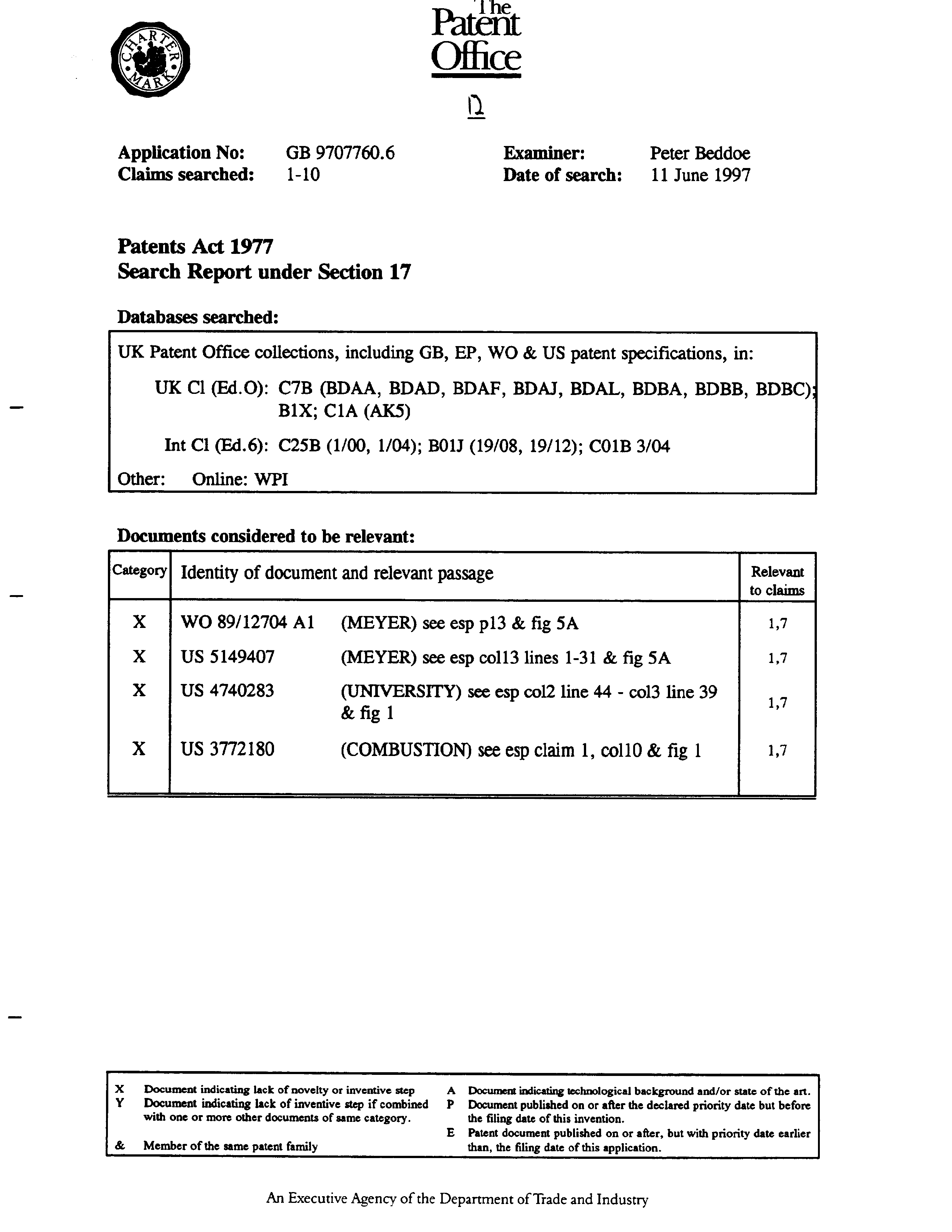
Application No: GB 9707760.6 Examiner: Peter Beddoe
Claims searched: 1-10 Date of search: 11 June 1997
Patents Act 1977
Search Report under Section 17
Databases searched:
UK Patent Office collections, including GB, EP, WO & US patent specifications, in: UK Cl (Ed.O): C7B (BDAA, BDAD, BDAF, BDAJ, BDAL, BDBA, BDBB, BDBC);
B1X; C1A (AKS)
Int Cl (Ed.6): C25B (1/00, 1/04); BO1J (19/08, 19/12); CO1B 3/04
Other:
Online: WPI
Documents considered to be relevant:
Category! Identity of document and relevant passage Relevant to claims
xX US 4740283 (UNIVERSITY) see esp col2 line 44 - col3 line 39 7
Xx US 3772180 (COMBUSTION) see esp claim 1, coll0 & fig 1 1,7 X Document indicating lack of novelty or inventive step A Document indicating technological background and/or state of the art. Y Document indicating lack of inventive step if combined P Document published on or after the declared priority date but before with one or more other documents of same category. the filing date of this invention. E Patent document published on or after, but with priority date earlier & Member of the same patent family than, the filing date of this application.
An Executive Agency of the Department of Trade and Industry
Provenance
- Collection
- Patents citing this work
- Original assignee
- Davies Caroline Jane
- Pages
- 18
- Method
- pdftoppm 300dpi + tesseract 5 (eng)
- Patent office record
- patents.google.com →
- Source
- Google Patents citing-documents table
- Inventors
- Christopher Robert Eccles; Davies Caroline Jane
- Published
- 1998-10-21
- Transcribed from
- patentimages.storage.googleapis.com →