patent · GB2311846A
Solar generator
8 October 1997
Page 1 — bibliographic record
«a UK Patent Application o»GB «2311 846 awA
(43) Date of Printing by UK Office 08.10.1997
(30) Priority Data
(86) International Application Data
(87) international Publication Data
(71) Applicantis)
Johann Zimmermann
Santisweg 10, D-88281 Schlier,
Federal Republic of Germany
Johann Zimmermann
(74) Agent and/or Address for Service The Johannes-Field-Generators UK Limited 20-22 Bedford Row, LONDON, WC1R 4JS, United Kingdom
(51) INT CLS
(52) UKCL (Edition O)
(56) Documents Cited by ISA
(58) Field of Search by ISA
INT CL® HO1L, HO2K , HO2N
(54) Solar generator
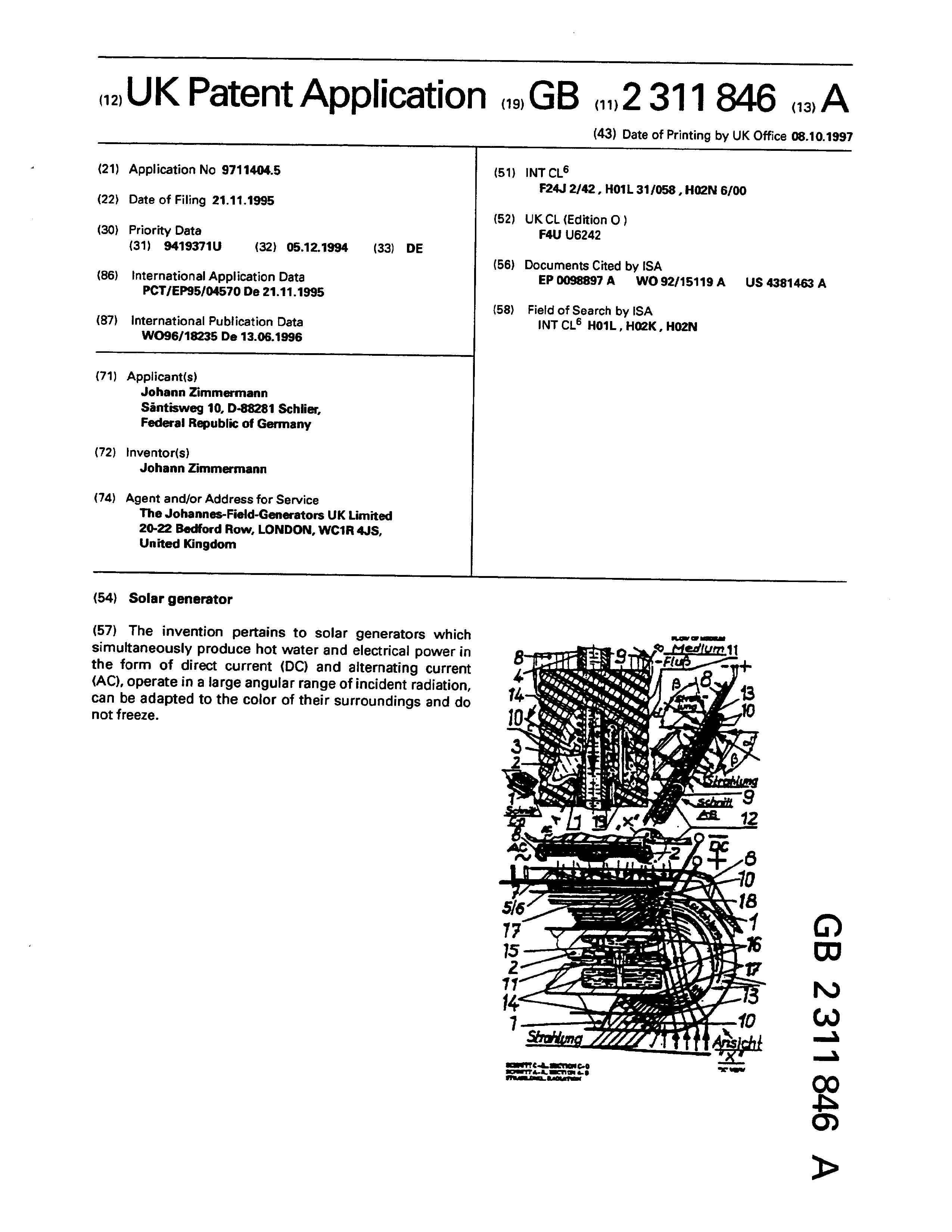
(57) The invention pertains to solar generators which simultaneously produce hot water and electrical power in the form of direct current (DC) and alternating current (AC), operate in a large angular range of incident radiation, can be adapted to the color of their surroundings and do not freeze.
athe ZZ T Aight
soertiak crores ~ww eke fearon
Page 2
Drawing sheet — no readable text.
Page 3
SUN GENERATOR
Technical Area:
The invention refers to sun generators which generate electric current preparing hot water at the same time and this in the sun generator’s layers passed on after the other by radiation, the same being non-dazzling and adaptable in color for the observer according to their environment and which can be operated in a large angle area (about 230 degrees) - to the direct radiation incoming - to their active surface and which, as the case may be, possess a device against freezing.
Level of technique: Till now, no solar generators are known which present the characteristics of this invented sun generator.
A research of the German Patent Office referring to my notification of registered utility model G 94 19 371.1, notification day 5th December 1994, verified this fact. I was named the "hybrid solar Energy generating system" by D.E. Soul, with the U.S._ Patent No. 4,700,013 of 13th October 1987 uses indeed fluid-cooled solar cells, nevertheless these cells are not cooled directly like in my sun generator, the warmth is just received by a holding system.
Moreover, in order to generate electric current and thermal energy at the same time with this system, with expensive devices such as polarization filters, the radiation must be divided into long wave and short wave radiation, whereby the efficiency rate of the energy transformation is
diminishing.
Page 4
Also the devices to be employed in this system are expensive and may be susceptible to failures, so that they are not suitable for small and maintenance-free operating systems like the system of the invented sun generator. At the invented sun generator, constantly 40 watts of delivered photovoltaic power additionally to 100 watts delivered thermal power have been measured, opposite to usual separated solar generators with average 25 watts of electrical/50 watts thermal power. Moreover, the temperature of the newly cooled sun generator remained constant during the measuring period (6 hours), whereas the temperature in the usual photovoltaic solar generators was rising while the deliverable electric
power during measuring time diminished.
Presentation of the Invention:
According to claims 1-12 of this patent application, the
sun generator possesses in the hose(s} (2) and in the inner
-hose(s) (3) and the winding(s) (1) winded/put around the
hose(s) (2) and/or the inner hose(s) (3) and the light transmitting system (1, 10, 17) and the photovoltaic active coating (13) therein, in combined effect with a permanent or remanent magnetizable medium circulating automatically or by force, and with the transmission of the radiation emitting on the sun generator to the medium (11)/water (9), and to the photovoltaic coating(s), a combined possibility to transform radiation of different waves when passing through, to transform into heat and current without loss, whereby the
medium (11) additionally in by-pass connection to the
Page 5
thermosiphon system active in series connection by heating resistors (14) and pumps (15) additionally to the heating-up of the magnetizable medium (11) and of the inner tube (s) (3) through floating medium - especially water - is moved and so for current generating, additionally to the current generated in the sun generator, together with coils, isa system for induction of efficiency rate in this height till now unknown, » at the generation of e.g. hot water and/or electrical current. The hoses and inner hoses (2, 3) of the integrated heat changer transform the radiation directly or indirectly via a system of resistances and Foucault current in the sun generator - totally or partially also used against freezing of the transport medium for heat exchange (11) and the medium (9) in the inner tubes - in.-warm/hot water or in current. The windings (1), mostly manufactured of colorable plastic or any other suitable material such as light transmitting fibers (photovoltaic), are systems for the light and/or electrical/magnetical or acting field in any other kind as a compact system of lenses and are saturated with all suitable cross sections and, as the case may be, grooves (10) in it/them or as energy transporting layered/bundled and with an energy-transforming coating as e.g., doped silicon layers, according to the patent application DE 42 05 721.
In this version, the light transmitting fiber/energy transporter is surface-covered in this way with a vaporized coating of a mixture of powdered substances and hardening working material according to the patent application
PCT/DE90/00891, EP 90917048 .2-2309/0512998 and DE 39 38 881.
Page 6
In the now following part of the description some of the possible embodiments, which are according well to the research results of Terry I. Chappel, Phys. Letters, 4.76, Department of Electrical Engineering and Computer Science, University of California, Berkeley, California 94720, for the combination of photovoltaic and thermic obtaining of energy, are represented for the combination of photovoltaics and thermics.
These sun generators can be mounted on house walls (12) or on house roofs or by themselves. The integrated heat exchanger is heated thereby. The grooves (10) of the winding(s) (1) around the hose(s) (2) reflect or respectively transmit the sun light/radiation from their environment in a way that the house wall or the roof or the support where the sun generator(s) is/are mounted, till to an observing angle of about -60 degrees and +60 degrees (a, 8) from the normal to their surface seen to the width, let it appear bright, on behalf their construction as windings (1) containing grooves (10) of transparent plastic or of any suitable material, is reflected light/radiation, and only over an angle of more than e.g. 60 degrees for the angle(s) (qa) and the angle(s) (8) is transmitted, i.e., on the surface of the hose (2), winded by the windings (1). An observer from bird’s eye perspective sees at an angle (a) of more than approximately 30 degrees the sun collector as a black surface, optically deformed to a smaller length than its current length. That means that the sun collector’s surface which is at disposal for the adsorption of for example sun radiation, according to the
sun's position in comparison with its largest surface, its
Page 7
height (at the same measurements of the compared collectors/positions), is smaller. That however is without any disadvantage by the normally existing perpendicular surfaces on house walls, till now mostly unused for that purpose, what can be employed without any constraint. The sun collector of new kind of construction, now can be adapted to all usual house wall colors, what is indispensable by esthetic reasons by using the surfaces of a house, which are e.g. perpendicular. A worldwide research realized on the base of my verifications and sketches in the writing of October 24, 19394, to WINUB, Dr. Andreas Wolf, Leverkusenstieg 28, 22761 Hamburg, has proved, that up to the 28th October no working Material or combined material was known, which reflects light depending on direction, respectively can emit partially at the same time.
According to my sketch on sheet 2 of my writing of October 24, 1994 to Dr. Andreas Wolf, Leverkusenstieg 28, 22761 Hamburg, as my cosigned person - the writing is enclosed for reasons of protection of the priority of the application of registered utility model (05-12-94) - the light transmitting parts are named as optical transmitting lenses, the frontal side approximately kept against the direct inversion of sun light and their outer surface being photovoltaic active, emitting radiation to the collector foil and light/radiation reflecting perpendicularly to the main axes to them. By means of manufacturing now the winding (s) is/are surrounding a hose (2). The winding part mounted on
the reverse of the hose at flat pressed hose (2) and the inner
Page 8
hose (3) of one/several closely lying windings of transparent plastic or of any other suitable material, beams on its reflecting surfaces - the lenses/prisms - and which have also other geometrical and/or non-geometrical definable shapes for reflection and/or light/radiation emission, or transmits them totally or partially via the system of lenses and/or light transporting system (1, 10, 17) to the coatings of the photovoltaic element (s) (17) (5, 6) and to other such elements in/on the hose (2)/the winding (1).
The circuit is like that from the delivered direct current (DC) is generated an alternating current (AC), while the magnetic field around the expanded metal (8) of iron material or any other remanent and/or permanent magnetizable material, e.g. elementary magnets in the mixture of glycol and water mixed in a 50:50 rate (11), transports finely dispersed remanent and/or permanent magnetic particles by the thermosiphon effect, as the case may be, supported by thermal effect of heating resistances and/or by pumping effect of the pumps (15) - cross section AB with arrows arranged under different angles and perpendicularly, shows the emission of radiation, which originates the medium flow (11) (radiation(s) by any angle hitting on the sun collector) - and by the medium flow in the magnetic field of the expanded metal, respectively of any other suitable magnetic/electrical transmitter, which are transported and deliver an inductive current - alternating current - to the connections (7) named "AC". This kind of generation of alternating current delivering hot water at the
same time is new. The heat exchange from the collector to the
Page 9
store for warm water is realized in the "sun generator" in the inner tube (3) floated by water, by means that the warmth flux passes through the tube wall of the hose (2) and the transporting medium of warmth and elementary magnetic particles surrounding the tube.
The expanded metal (8) is a support for the hose (2), the surrounding winding(s) (1), the inner tube (3), the connecting pieces (4), the electrical.resistances (5, 6, 7) anda photoelectric active covering (13) on the elements (13) on the elements (5/6, 17, 21, 10). The expanded metal is screwed with screws and plugs, e.g. on one/a house wall and is mounted with e.g. quick binding concrete in order to keep distance and for fastening. The inner tubes are preferably of a harder Material than the connecting pieces (4) and the hose (2), so that for fastening is used the adhering tightening and sealing system known and protected by the utility model G 9207218.6 and registered according to PCT/EP92/01181. In that system the mandrel - here the inner hose - opens out the hose - here the connecting piece (4) - and gets pulled tighter with ~ increasing tension load. A light upsetting, however, is sufficient to loosen the connection made in a relatively easy way. In the version shown according to Figure 1, sheet 1/1, as material is used for the hose (2) an elastomer thermoplastic stable at over 140°C of ethylene-butylenepolystyrol,- which is transparent for light and can be colored in any color. Moreover, this material is resistant to low temperatures and can be very well welded with polypropylene.
For the inner tubes is used the same material as for the hose
Page 10
(2), but in order to obtain the necessary hardness in irradiation cross-linked version. The winding(s) at that version of sun generator consist(s) of transparent polymethylmetaacrylate (PMMA), so as for example it is extruded as mass pre-material for granulate. The cross section form of the used winding(s) material is lens-shaped and it is very appropriated for winding around the hose (2) in one coil or several arrangement on the hose (2); the grooves (10) have been worked out in the winding(s) before or after the hose being winded around. The hose is manufactured according to the procedure indicated in the patent application P 4142684.3 and with the machines and tools according to G9106626.3, further according to DE 3938811 Al, DE 4037201 Al,
After winding around, the winding body together with the inside formed inner tube (3) is pressed flat - e.g. according to PCT/DE90/00891 - and, as case may be, provided with grooves
Best Way to Realize the Invention:
The sun generator in the following version is mainly of thermoplastic, which permits in a temperature range from about minus 70 degrees up to plus 170 degrees Celsius - according to patent application DE 4205721 - to produce highly solid, radiation resistant, form stable, printable and temperature resistant foils (2, 5/6) with sparings (16) with fabric inlays, which minimize the expansion and have integrated in
zones of the laminate - the fabric of this combined working
Page 11
material covered by plastic, electrical spools (14) and pumps (15). According to the invention, there are available printable plastic foils with several coatings of the photovoltaic elements, e.g. in the high-vacuum processing, by evaporating of a silicon compound on highly flexible thin plastic foils of about only 0.2 mm thickness to the already printed connections.
The laminated foils, bonded one to each other by welding or by gluing, with about 0.3 mm thickness and with connections and with inlaying electronic components are gas-tight. The fluid floated tubes (2) and the inner tubes (3) are fitted one into each other and then flat pressed and they are forming multilayer photovoltaic elements out of about 10 single plastic foils with evaporated photovoltaic Coating on it, together with the coated fiber bundles (17) located in the winding (1), which arise from the groove(s) (10) on the front part of the winding (1).
The basic working material is produced from irradiation cross-linked plastic of e.g. a ethylene/butylene/polystyrol mixture and the glass fiber and the covered glass fiber fabric being rolled at the same time, the temperature resistance and other working material characteristics of raising filling materials being obtained, at the same time calibration of the basic working material foils and the laminate manufactured therefrom, using e.g. silicon compound material.
In this version the photovoltaicly generated current is partially used to transport/circulate the elementary magnets
in the magnetic/magnetizable fluid (11) Supporting the
Page 12
thermosiphon effect at sun irradiation with help of pumping elements and/or heating resistances - at resistance coils around the inner tube(s) and passing by and, casually to the
In this version the sun generator is totally only about 12 mm thick and can be coiled in a roll, and in coiled form it
can be hung on house walls and easily be removed therefrom.
Short Description of the Sketches:
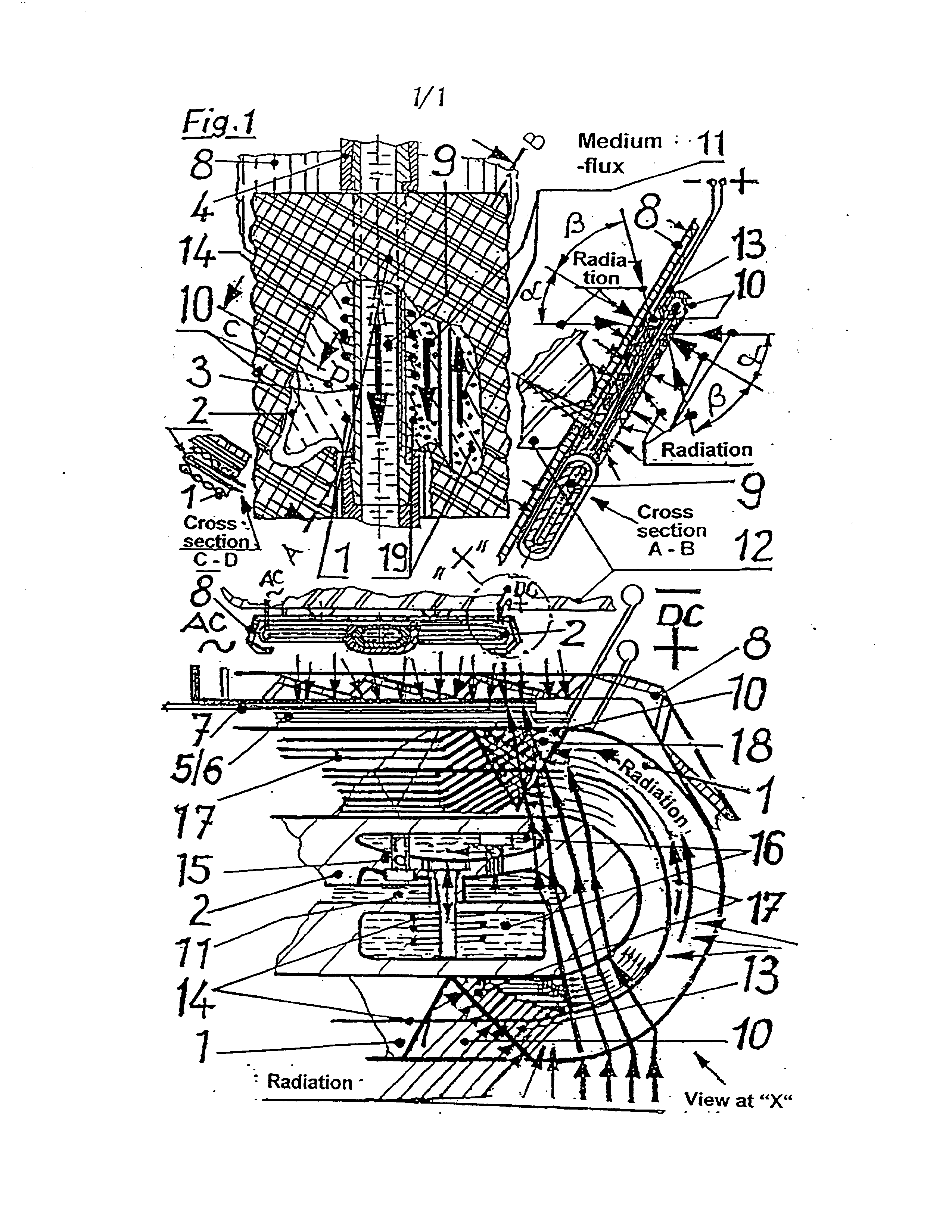
The illustration 1 shows the design of a sun generator such as represented in the description and the patent claims.
In the front view the medium flux of the warmth transmitting medium (11) is shown by boldly designed arrows and in opposite direction. A coil (14) is winded around the inner tube (3), the coil is floated by the medium (11) fed up with small magnets (19). The inner tube (3) is shown in cross section and it shows the medium (9) flowing through and its preferred flowing direction with a boldly drawn arrow. Here the medium is drawn in broken line as liquid (water).
The drawing represents the generator sun generator with
' an opened front side in order to represent the opposite
winding (1) on the front and the rear side together with the grooves (10) located inside. The cross section A-B, realized across the front view, shows the emission of the radiation and the mounting of the generator by means of expanded metal on a house wall (12) with that version.
The cross section C-D shows the lens-like shape of the
winding (1) of the hose. In the top view in the cross section
Page 13
can be appreciated the expanded metal (8), as it embraces the hose with the winding. Also the current delivering points are shown and labeled with AC(~) and DC(+,-).,
In the view "X" can be appreciated the connections in enlarged size.
Also here is shown the layering of the photovoltaic elements (5/6) and of a resistance (7), which are mounted on the reverse of the winding (i) in that version of the sun generator. In the winding there are shown the grooves (10), which are output and end for the light transmitters (17), which are provided with a photovoltaic active coating (13) like the plate shaped elements (5/6). In the hose (2) there are shown the sparings (16), wherein the pump (15), designed here as a membrane pump, is integrated.
The radiation is exemplarily indicated in its itinerary through the sun generator with boldly drawn lines with several arrows inside. Moreover, the radiation is shown from the reverse, passing through the: expanded metal (8). The zone of condensed radiation is labeled with 18 and shows in this position the meeting of radiation fraction from the winding
and the hose (2).
Page 14
Claims:
1. Sun generator, characterized by that it is joined by an outer tube (2) and an inner tube (3) and that the outer tube is equipped with a system of lenses (1, 10), which reflects radiation of any kind and in any angle at any intensity shining on the sun generator at the same time or partially and/or transmits to the tubes (2, 3), and in and/or on the system of lenses (1, 10) where are electrical resistances, which generate a direct current (DC) and this direct current (DC) possesses an electromagnetic field in the electrical resistances as active field. These resistances, between the outer tube (2) and the inner tube (3), by means of magnetic particles (19), contained in a fluid or any other suitable medium being circulated by thermal effect and/or pumps, in form of specially permanent and/or remanent magnetic particles, preferably floating in it, generate a pulsing current, preferably an alternating current (AC), converting a
part of the radiation into thermic energy.
2. Sun generator, according to claim 1, characterized by that the heat exchanger is fitted as a tube (3) - here inside tube - and that it is additionally heated by the fields in the sun generator as direct current (DC) and/or pulsing
current, especially alternating current (AC).
3. Sun generator, according to claims 1 or 2, characterized by that in the illustration (Figure 1) shown
here, an extended lens (1), with the optical cross section to
Page 15
the beam reflection and/or at the same time to the transmission of the radiation, is winded in one or more coils around the outer hose (2) and is chained, as the case may be, adhesively or cohesively, and that this lens (1) possesses
coil form with grooves (10) for reflection.
4. Sun generator, according to claims 1, 2, or 3, characterized by that in the medium between the outer and the inner tube (2, 3) there are permanent and/or remanent magnetic particles especially emulsified and that it possesses an
additive like antifreeze agent against freezing.
5. Sun generator, characterized by that it is preferably situated perpendicularly, @.g. on house walls ona supporting construction of expanded metal (8), the same is kept at a distance for ventilation of backside, on the plaster on a house wall or any surface which stands perpendicularly or in an angle to the surface of the earth and which transforms
the incoming radiation in thermal energy and/or current.
6. Sun generator, with the tubes (2, 3) of thermoplastic elastomer, according to the color especially of the house wall, and that can be colored, as well as with a coiling, which also can be colored, and the colored part of
this sun generator let pass light/radiation.
7. Sun generator, possessing on its surface any
suitable optical kind of lenses, which reflect or transmit
Page 16
light at the same time leading it to the photovoltaic resistances and/or to radiation-converting devices such as
plastic foils.
8. Sun generator, consisting of layers with reinforcing fabric which enables an enlargement manifesting itself only at specified positions, and that these layers can be printed,
welded and conglutinated and let pass radiation.
9. Sun generator, consisting of layers coated with a photovoltaic active covering by evaporation and/or mechanical coating according to the patent application P4140875.6 or
10. Sun generator, consisting of radiation-transporting bundled working material, transports radiation in its longitudinal direction and carries the photovoltaic active coating on its outer surfaces and possesses electrical contacts for conducting the photovoltaic current originated in/fon the fibers of the fiber-bundled working material and lets pass radiation in the transversal direction to the
bundles fibers which are coated.
11. Sun generator, according to patent application 4142684 manufactured of tubes with layers with photovoltaic
active coating inside.
Page 17
12. Sun generator, reinforced with fabric respectively with clothing; can be printed, coated, transports radiation and thermal energy and possesses the properties named in the patent application 4205721 and/or 4201759.9 and is
manufactured accordingly.
Page 18
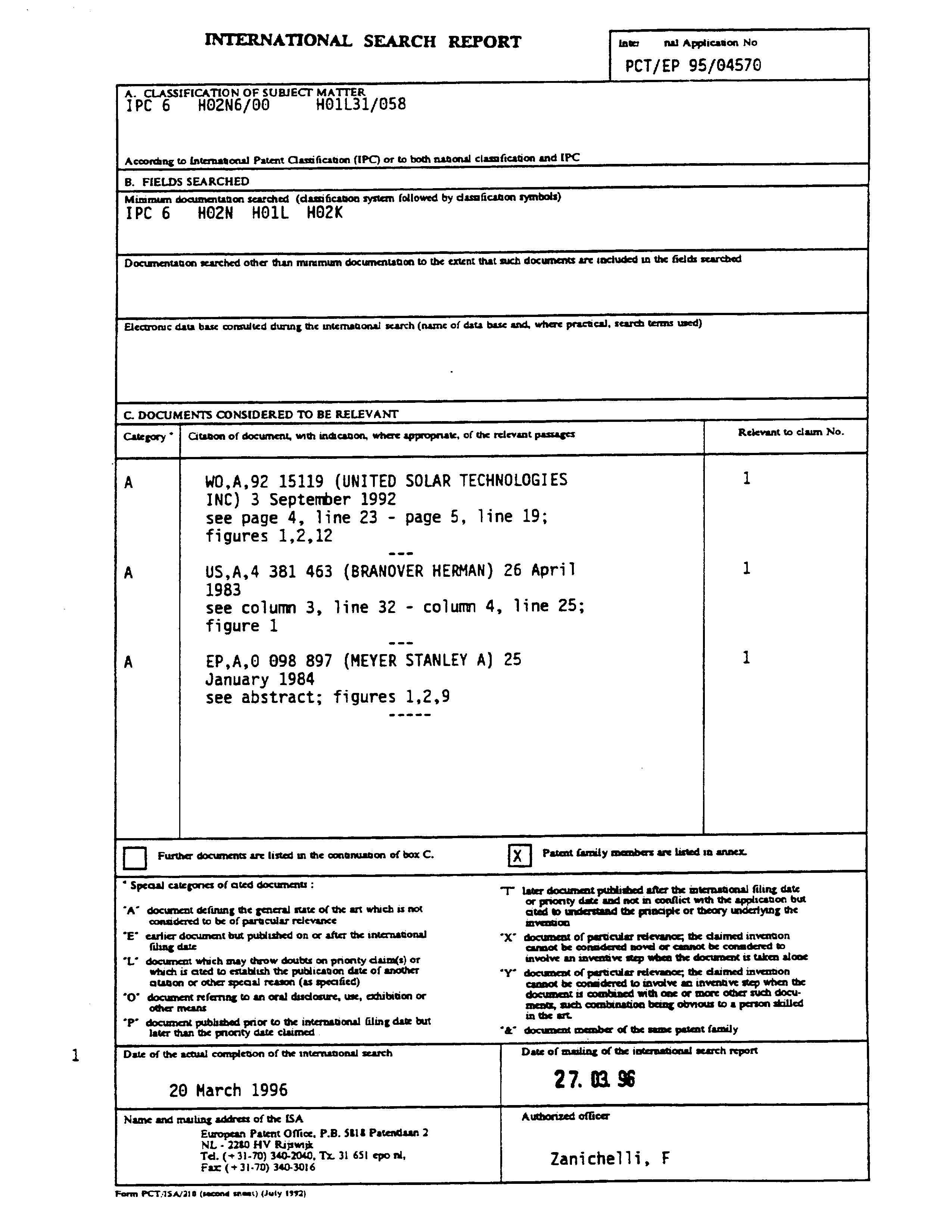
INTERNATIONAL SEARCH REPORT int nal Application No
‘A._ CLASSIFICATION OF SUBIECT MATTER
According to international Patent Classification (IPC) or to both national ciasnfication and [PC
B. FIELDS SEARCHED
Minimum documentation searched (classification system followed by clasaficaton symbols)
IPC 6 HO2N HO1L HO2K
Documentation searched other than miramum documentation to the extent that such documents are inciuded in the fields searched
Electronic data base connulted during the intemnagonal scarch (name of data base and, where practical, search terms used)
C. DOCUMENTS CONSIDERED TO BE RELEVANT
Category * | Gi of & Relevant to claim No.
with indicagon, where appropriate, of the relevant passages
A WO,A,92 15119 (UNITED SOLAR TECHNOLOGIES 1
INC) 3 September 1992 see page 4, line 23 - page 5, line 19;
figures 1,2,12
A US,A,4 381 463 (BRANOVER HERMAN) 26 April 1
see column 3, line 32 - colum 4, line 25;
figure 1
January 1984 see abstract; figures 1,2,9
C] Further documents are listed un the conanuagon of box C. [x] Patent family members are listed 1n annex.
“s§ te, ted document: :
peaal categones of ated doc “T” later document published after the international filing date
or prionty date and not in conflict mth the application but
“A” document defining the general state of the art which is not considered to be of parucular relevance
°E’ earlier document but published on or after the international filing date
*L’ document which may throw doubts on prionty claim(s) or which is ated to estabitsh the publicaton date of another atanon or other speaal reason (as specified)
*O° document referring to ani oral disclosure, use, exhibition or other means
*P’ document published prior to the internaGonal filing date but later than the pnority date claimed
cited to understand the principic or theory underlying the invention
°X” document of particular reievance, the daimed inventon cannot be considered novel or cannot be conadered to involve an inventive step when the docurnent is taken alone
*Y’ document of particular rel s the claimed i cannot be considered to involve an inventive sep when the document is combined with one or more other such document, such combination being obvious to a person skilled in the art
*&° document member of the same patent family
Date of the actual npl of the inter | search
Date of mailing of the international search report
Name and mailing addrets of the [SA
European Patent Office, P.B. 5818 Patendaan 2
NL - 2280 HV Ripwik
Authorized officer
Zanichelli, F
Form PCT.15.A4/2108 (second sneat) (Juty 1992)
Page 19
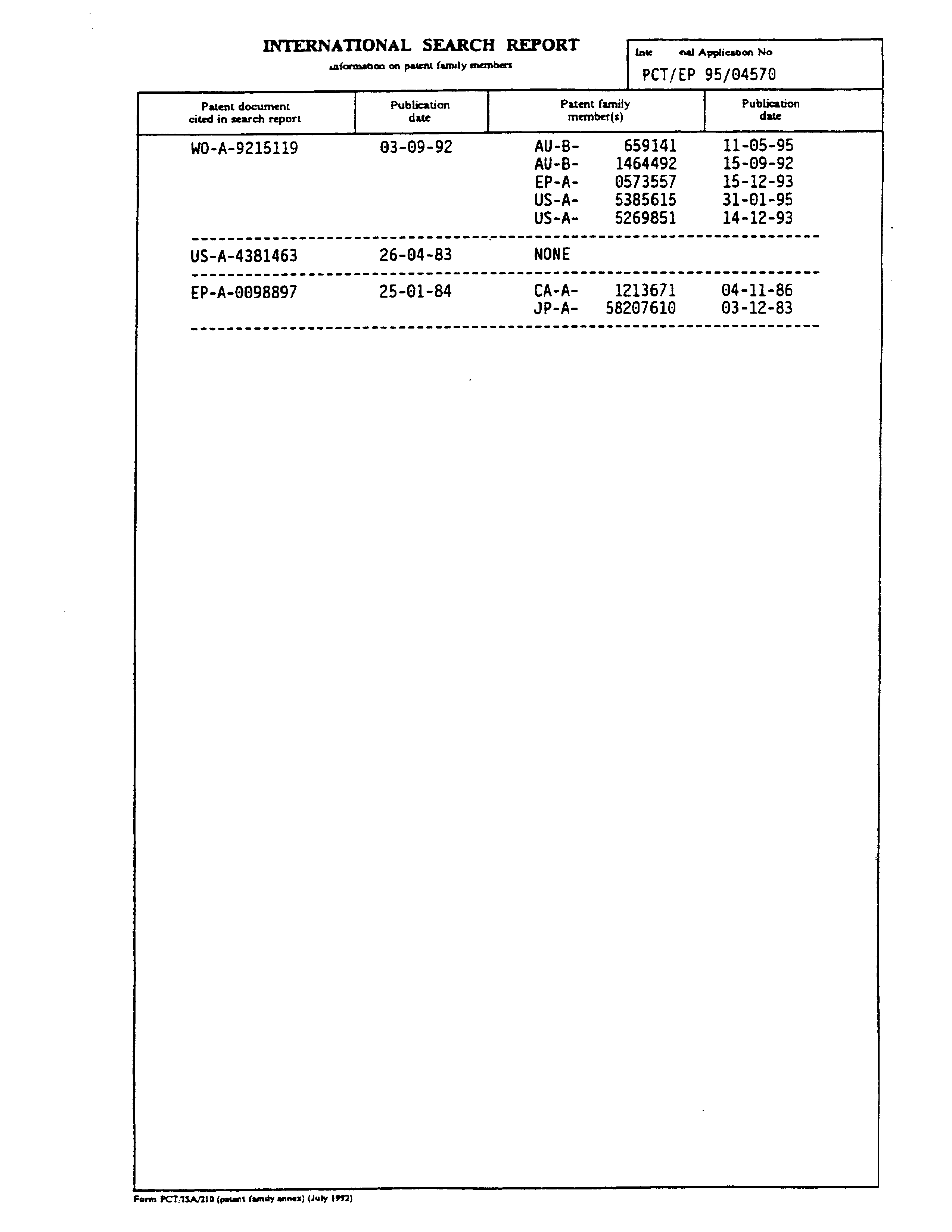
INTERNATIONAL SEARCH REPORT me aul Appiunon Wa
saformation on patent family memvers PCT/EP 95/04570
Patent document Publication Patent family Publication cited in search report date member(s) date
wen wwe we waste eee sew ee www ewe ces e ee wma nase we awe tame wes eww eww ewe wena ese=
wwe een mn meee wee ewe conn ee en seam wa rw een mwa enw es ene wee meee eee wee ee eee eee
wee eet eee ene ees cartes ewe moe new eawt ewe enw wen eee woes es wate ewe tem eee ese ren
Form PCT.1SA/210 (patent family annex) (Juty 1992)
Provenance
- Collection
- Patents citing this work
- Original assignee
- JOHANNES FIELD GENERATORS UK L
- Pages
- 19
- Method
- pdftoppm 300dpi + tesseract 5 (eng)
- Patent office record
- patents.google.com →
- Source
- Google Patents citing-documents table
- Inventors
- Johann Zimmermann; JOHANNES FIELD GENERATORS UK L
- Published
- 1997-10-08
- Transcribed from
- patentimages.storage.googleapis.com →