patent · EP4292978A1
Reactor for dissociation of aqueous solutions and method of dissociation of aqueous solutions
20 December 2023
Page 1 — bibliographic record
(12) EUROPEAN PATENT APPLICATION
(43) Date of publication: (51) International Patent Classification (IPC): 20.12.2023 Bulletin 2023/51 C01B 3/06 (2006.01) C01B 3/04 (2006.01)
(21) Application number: 23176753.4 G01N 27/06 (2006.01) G01N 27/22 (2006.01)
(22) Date of filing: 01.06.2023 (52) Cooperative Patent Classification (CPC):
(84) Designated Contracting States: (71) Applicant: Adasune s.r.o. AL AT BE BG CH CY CZ DE DK EE ES FI FR GB 50004 Hradec Kralove (CZ)
NO PL PT RO RS SE SI SK SM TR (72) Inventor: Korbel, Viktor
Designated Extension States: 37802 Simanov (CZ)
Designated Validation States: (74) Representative: Sedlák, Jirí
KH MA MD TN Okruzni 2824 370 01 Ceské Budejovice (CZ)
(54) REACTOR FOR DISSOCIATION OF AQUEOUS SOLUTIONS AND METHOD OF DISSOCIATION
OF AQUEOUS SOLUTIONS
(57) The invention relates to a reactor (1) and to a (3) between them to create an intense non-uniform elecmethod of using it, which comprises a hermetically sealed tric field which begins to vibrate the molecules of the container (2) inside which are electrodes (3). After appli- aqueous solution sufficiently to cause dissociation of the cation of an aqueous solution between the electrodes aqueous solution into dissociation products. (3), it is possible by controlled charging of the electrodes
Processed by Luminess, 75001 PARIS (FR)
Page 2
1 EP 4 292 978 A1 2
Description disadvantageous that electrolyte and electrodes have to be used, which complicates the consideration of simply
Field of technology using water, as the only feedstock, in the hydrogen and oxygen production process.
[0001] The inventive device and method are used to 5 [0007] At the same time, it is known that the cleavage dissociate aqueous solution molecules using an electric products of aqueous solutions can be used in the analysis field. The products of the dissociation of aqueous solu- of the chemical composition of aqueous solutions. It is a tions can serve as fuel in the energy industry or be sub- fact that there is a growing demand among those skilled jected to measurements to analyse the composition of in the art for an analysis of the chemical composition of the aqueous solution. 10 aqueous solutions which is rapid, reliable and at the same time not demanding on the level of expertise of the ana-
State of the art lyst.
[0008] Chemical compositional analysis is known in [0002] The products of the dissociation of aqueous so- which the analyte, mixture or aqueous solution is exlutions can be used as fuel, as oxygen and hydrogen are 15 posed to known chemical agents with high reactive poamong the products of the dissociation of aqueous solu- tential, in particular acids, alkalis, free radicals. These tions. It is a well-known fact that ways are currently being agents react with the unknown substance, mixture or sought to address the energy crisis caused by the exclu- aqueous solution to form known salts and chemical comsion of fossil fuels from the energy industry. And one of pounds, from the presence of which the composition of the possible substitutes for fossil fuels is hydrogen gas, 20 the analyte is subsequently determined. which appears to be a suitable candidate for replacing [0009] Chemical analysis requires a laboratory and a the burning of fossil fuels. worker with a high level of expertise. In addition, perform- [0003] Hydrogen gas has the advantage of being wide- ing chemical analysis is dangerous and time-consuming. spread in the environment in the form of water. Each [0010] Another well-known method of compositional molecule of water contains two hydrogen atoms and one 25 analysis is spectrometry, which uses electromagnetic raoxygen atom. When hydrogen burns, a large amount of diation. The atoms of each element present in the sample energy is released and the product of combustion with being analysed absorb electromagnetic radiation, or emit oxygen is water vapour. This is a big advantage over electromagnetic radiation, of a specific wavelength specfossil fuels, which release greenhouse gases, toxins and trum. By knowing this behaviour of the atoms, it is posdust when they burn. 30 sible to determine the chemical composition of the sam- [0004] The disadvantage of these pure gases is their ple being analysed.
high reactivity, which is very dangerous in case of im- [0011] Spectrometric methods are very accurate but proper handling, accident or malfunction. It is therefore require very well calibrated instruments, including propdesirable that the pure gases should not be stored in erly prepared samples. On the other hand, optical speclarge volumes in tanks, but that there should be a facility 35 trometric instruments can be operated by trained personand method for their continuous production before im- nel without a chemistry background. The disadvantage mediate consumption. This would be advantageous, of spectrometric analysis is that it cannot analyse the since clean water would be stored in the tanks as a feed- composition in the optically opaque sample to be anastock, the eventual leakage of which from the storage lysed.
tank is a minor safety risk. 40 [0012] This problem of an optically opaque sample is [0005] Another disadvantage of using pure hydrogen solved by spectrometric methods using ionising radiaand oxygen as a replacement for fossil fuels is the com- tion, e.g., fluorescence analysis, where secondary radiplexity of production, as breaking down a water molecule ation is detected on an ionising radiation detector. The into atoms is a relatively complex process. disadvantage of these methods is that ionising radiation [0006] An example of the well-known production of hy- 45 is a health hazard.
drogen from water molecules is electrolysis, in which wa- [0013] Another well-known type of compositional analter is mixed with an electrolyte and then a direct electric ysis is thermal compositional analysis, in which the samcurrent is passed through it. At one of the electrodes, the ple is exposed to increasing temperatures. By knowing electric current causes oxygen to be emitted from the the behaviour of the chemical substances, it is possible electrolyte in addition to other atoms, and at the other 50 to determine the composition of the analysed sample by electrode, hydrogen is emitted from the electrolyte in ad- the temperature at which changes occur in the sample dition to other atoms. Adversely, during electrolysis, the (evaporation, chemical reactions with the atmosphere, other atoms bind to other atoms present, in particular to etc.).
atoms of the electrode material, and coatings are formed [0014] Even this method of composition analysis is not which may act as an insulating material making further 55 very suitable for mass deployment. Firstly, it requires a electrolysis difficult. Furthermore, it is disadvantageous controlled environment with the possibility of controlled to work with DC electric current, which is very life-threat- heating, including the capture of products released with ening even at low voltage levels. Last but not least, it is increasing temperature of the sample being analysed. In
Page 3
3 EP 4 292 978 A1 4
addition, this analysis must be carried out by a trained duce the tendency of fission products to form chemical person. bonds, so it is advantageous if the reactor is equipped [0015] The object of the invention is to create a device with at least one source of electromagnetic radiation to for dissociation aqueous solutions, which could only be stabilize the ions in the reactor space. The fission prodoperated by a trained worker, which could split aqueous 5 ucts gain energy from the incident photons, thereby resolutions to such an extent that the products of the dis- ducing their reactivity, which would otherwise cause a sociation could be used as a substitute for fossil fuels, high rate of recombination into new molecules. Similarly, Alternatively, it may be possible to determine the com- the magnetic field source helps to stabilize the fission position of the aqueous solution from the electrical char- product ions by arranging their spatial orientation within acteristics of the fission process, or to introduce the fis- 10 the sample through magnetic interaction between the sion products into a gas analyser to analyse the compo- magnetic field and the magnetic dipole of the fission prodsition of aqueous solutions with a detector designed for ucts.
a completely different state of matter. At the same time, [0022] Preferably, a gas analyser is included behind it is an object of the invention to provide a method for the reactor opening for analysing the composition of the cleaving aqueous solutions that is energy sustainable, 15 fission products. Data is obtained from the gas analyser without additional feedstock, and that is rapid for produc- to refine the results of the analysis by comparing the elecing cleavage products in abundance. trical characteristics of the cleavage process of an aqueous solution of unknown composition with empirically ob-
Summary of the invention tained cleavage results of known aqueous solutions. 20 [0023] It is advantageous if the electrodes placed in [0016] The problem is solved by using a reactor for the reactor are in the form of concentrically arranged and dissociation aqueous solutions according to the invention interposed cylinders. Experiments have shown that the below. behaviour of the electric field between cylindrical elec- [0017] The essence of the invention is that the reactor trodes embedded in each other has a positive effect on comprises a hermetically sealed container made of an 25 the dissociation of molecular bonds. electrically inert material, and further comprising at least [0024] It is further preferred if the electrodes are platetwo electrodes inverted to each other, which are inserted shaped, wherein they are provided with a means for into the hermetically sealed container of the reactor. This changing the width of the gap between the electrodes. arrangement yields a hermetically and electrically sealed By changing the electrode spacing, the thickness of the electrode capacitor whose dielectric will be an aqueous 30 dielectric lying between the electrodes is substantially solution. At the same time, it is important in the context changed, which affects the electric field generated beof the invention that the reactor exhibits at least one light tween the electrodes. If the distance between the elecsource for irradiating the space inside the reactor with trodes is varied during the periodic generation of a nonphotons. The cleavage products of the aqueous solution uniformly increasing electric field, an additional variable are highly reactive with a tendency to form new chemical 35 is introduced into the aqueous solution system, thereby bonds. By supplying energy with photons, their tendency reducing the probability that the aqueous solution moleto form chemical bonds is partially suppressed and the cules will assume an equilibrium state and will not build fission products can therefore be diverted for further up the energy required to dissociate their molecular processing. At the same time, the reactor is provided with bonds.
at least one opening for venting the gaseous fission prod- 40 [0025] The invention also includes a method for dissoucts. ciation aqueous solutions in a reactor according to the [0018] The advantages include that the reactor con- invention.
struction is simple but efficient. The electrodes define the [0026] The essence of the invented method of dissogap(s) for flooding with the aqueous solution. The reactor ciation aqueous solutions in a reactor is that a) the aqueis safe and can be sized as required. 45 ous solution is poured between electrodes, where it takes [0019] Preferably, the reactor is provided with at least the role of the dielectric of the capacitor. The aqueous one aqueous solution supply for continuous replenish- solution as dielectric is exposed to an electric field when ment of the aqueous solution and uninterrupted operation the electrodes are charged.
of the dissociation of the aqueous solution in the reactor. [0027] Further, the essence of the inventive method is [0020] It is also advantageous if the light source com- 50 that (b) a nonlinearly increasing electric field is generated prises a light emitting diode, preferably a UV light emitting between the electrodes by including the reactor elecdiode. Light emitting diodes produce less waste heat than trodes in a series-connected tuned LC circuit, until some conventional filament light sources. In addition, they are molecules of the aqueous solution are decomposed into suitable for miniaturisation, and are durable. UV light- fission products, wherein the ions of the fission products emitting diodes produce light at a wavelength that is 55 of the aqueous solution are stabilized by irradiation with shown in current experiments to be the most optimal for photons or a magnetic field. A variable and increasingly stabilizing fission product ions. intense electric field will excite the aqueous solution mol- [0021] In some cases, magnetic fields are used to re- ecules so intensely that they break down to form fission
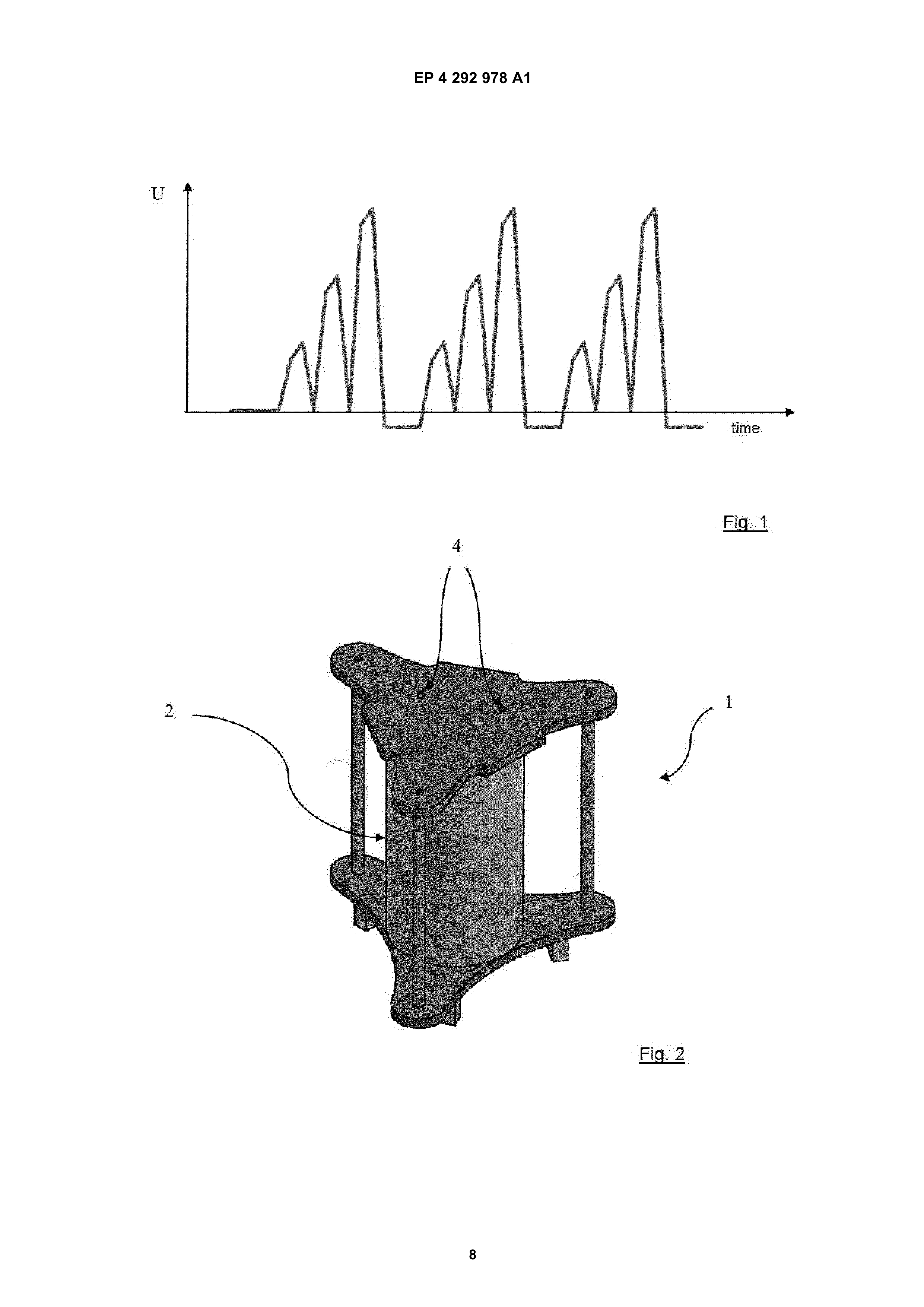
Page 4
5 EP 4 292 978 A1 6
products. in Figure 2.
[0028] Further, the essence of the inventive method is that, after c), the fission products are discharged through Example of the embodiment of invention an opening outside the reactor, whereupon method steps b) and c) are repeated as long as the aqueous solution 5 [0033] It is understood that the specific embodiments is present between the electrodes. At the same time, in of the invention described and illustrated below are premethod step (b), the parameters of the non-uniformly in- sented for purposes of illustration and not as a limitation creasing electric field are adjusted according to the cur- of the invention to the examples provided. Those skilled rent electrical capacitance of the capacitor formed by the in the art will find or be able to provide, using routine electrodes and the current amount of aqueous solution, 10 experimentation, a greater or lesser number of equivawhile the frequency of charging of the electrodes is varied lents to the specific embodiments of the invention defrom 50 kHz to 1 MHz. As the aqueous solution is con- scribed herein.
verted to fission products, the electrical properties of the [0034] The dissociation of aqueous solution molecules electrodes and the dielectric (capacitor) change, so the is achieved by repeatedly exposing the aqueous solution applied electric field gradually adapts to this change. It 15 molecules to an extreme electric field of varying tendency is also important that as the electrical conductivity of the that can supply the molecule atoms with the necessary aqueous solution increases, the frequency of charging excitation energy to overcome their mutual bonding. of the electrical charge in the capacitor increases. The [0035] The electric field must increase nonlinearly in fission products act as charge carriers, so that the con- its value in order for the molecules to be energetically ductivity of the dielectric between the electrodes increas- 20 stressed by the increase and decrease of the field. In es with increasing concentration. It is necessary to re- macroscopic layman’s terms, to more easily visualize the spond to this by changing the charging frequency. effect, the molecules of the aqueous solution must be [0029] Among the advantages of the inventive method vibrated with increasing intensity until the atoms bounce is that the molecules of the aqueous solution are electri- off each other.
cally decomposed without the need for the input of addi- 25 [0036] The electric field is generated between the electional raw materials. The decomposition of aqueous so- trodes 3 of the so-called capacitor, the dielectric of which lution molecules by means of an electric field is a cheap, is the aqueous solution. The non-linear increase in the efficient and almost maintenance-free method, which electric voltage, which directly proportional to the electric cannot be said, for example, of methods based on elec- charge on electrodes 3, is shown in Figure 1. As can be trolysis, which need massive electrodes. 30 seen from the figure, the electric voltage reaches a cer- [0030] In a preferred method according to the inven- tain limit, then decreases, then reaches a slightly higher tion, during method step (b), the electrical charging and limit, and this repeats until the molecules of the aqueous discharging characteristics of the electrodes with the solution release electrons during their dissociation, which aqueous solution dielectric are measured, and the elec- momentarily causes the electric voltage to drop below trical charging and discharging characteristics of the 35 the horizontal axis of Figure 1. Charging takes place only electrodes with the aqueous solution are compared with in the positive half-plane.
an empirically obtained database of electrical charging [0037] This process is repeated continuously as long and discharging characteristics of electrodes with aque- as aqueous solution is present between the electrodes ous solutions of known composition to determine the 2 of the capacitor and as long as fission products need composition of the currently grafted aqueous solution. 40 to be produced.
[0031] Experiments show that the electrical character- [0038] The frequency of the rise and fall of the electrical istics are unique for different compositions of aqueous voltage is modified in Figure 1 to help understand the solutions, so it is possible to analyse the composition of method, but in reality, the operating frequency ranges currently unknown aqueous solutions by comparing the from 50 kHz to 1 MHz, which means up to 1 000 000 currently measured characteristics with archived charac- 45 repetitions of the phenomenon in one second. This exteristics of aqueous solutions of known composition. treme stress on the bonds in the aqueous solution molecules causes them to break down. In addition, it has
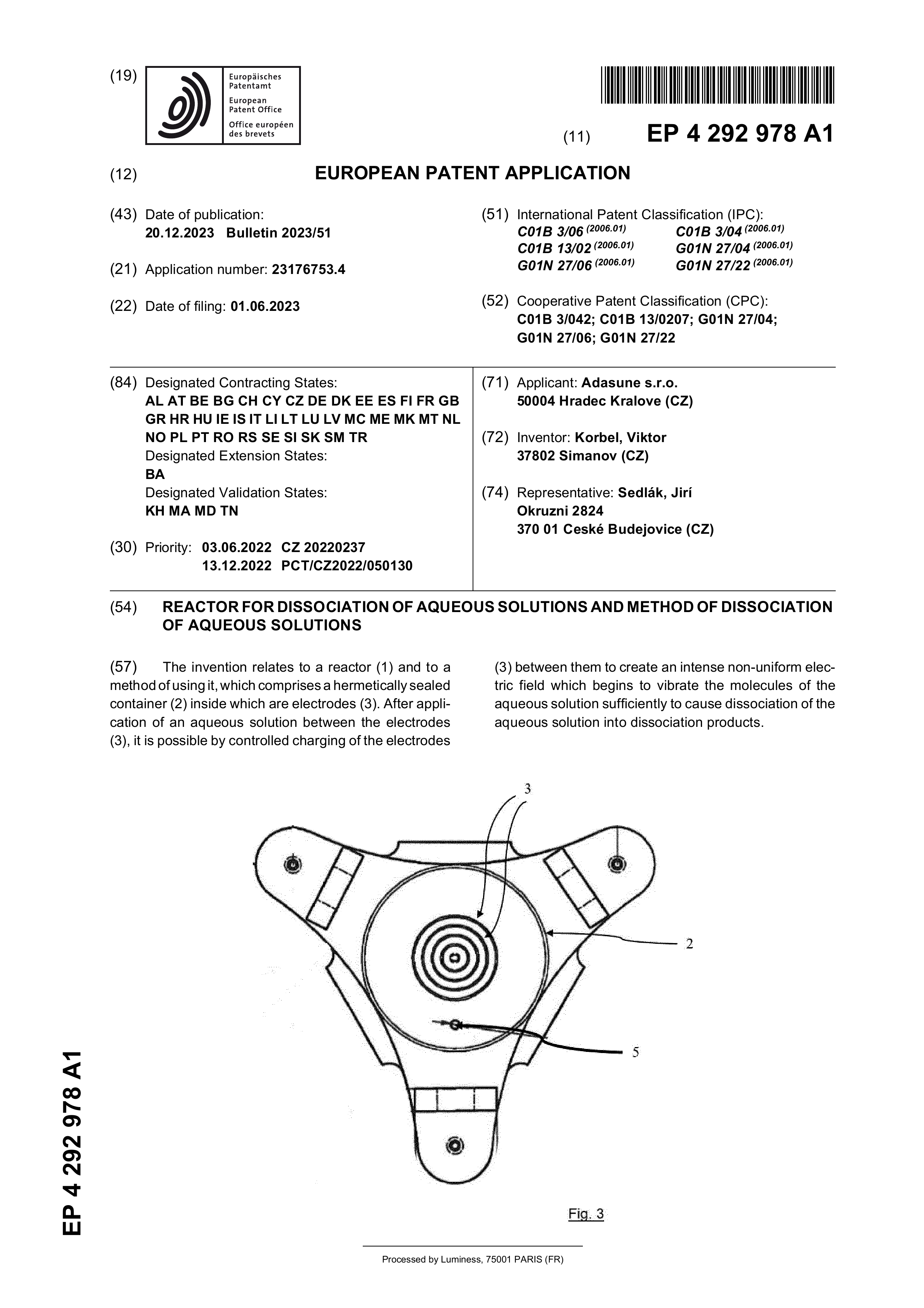
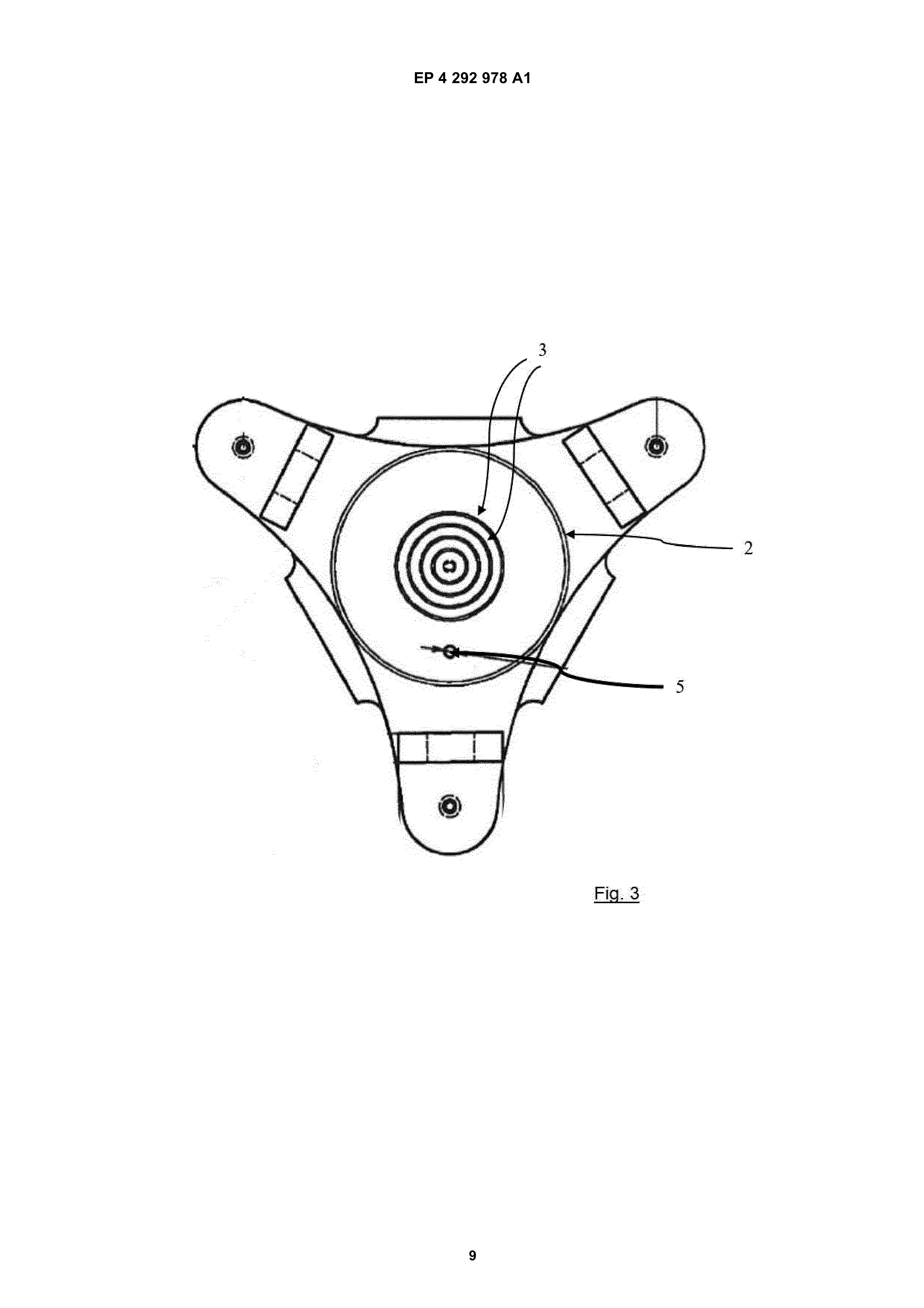
Description of drawings been verified that the conductivity of the aqueous solution between the electrodes decreases with increasing fre- [0032] The said invention will be explained in more de- 50 quency. This is important as it is possible to process any tail in the following illustrations, where: aqueous solution. Due to the higher frequencies, the electrical charge is concentrated at electrodes 3 and an
Figure 1 shows in a simplified graphic a periodically inactive region is formed in the gap between electrodes recurring increase in the electrical voltage 3 in terms of electrical conductivity. Practical experiments applied to the reactor electrodes, 55 with the laboratory reactor 1 showed that frequencies up Figure 2 shows a simplified reactor model of the de- to 280 kHz were sufficient for distilled water, frequencies vice, from 720 kHz to 1 MHz were applicable for salted water Figure 3 shows the bottom view of the reactor model with 5 % salinity table salt, while frequencies from 430
Page 5
7 EP 4 292 978 A1 8
kHz to 650 kHz worked for tap water. with water. There are five tubular electrodes 3 in total, [0039] As for the amplitudes of the working electrical as shown in Figure 3.
voltage, this depends on several factors. Firstly, it de- [0045] Figures 2 and 3 also show openings 4 for the pends on the electrical properties of the aqueous solution removal of gaseous fission products, and opening 5 for to be treated, then on the surface area of the electrodes 5 the continuous supply of aqueous solution. 3 and the distance of the electrode surfaces 3 from each [0046] In the non-depicted example embodiment of the other, then on the amount and temperature of the water, invention, the electrodes are planar and are parallel to then on the degree of dissociation of the molecules, etc. each other to create a free space between them for the [0040] For this reason, the electrodes 3 of reactor 1 dielectric, which will be the sample of the aqueous soluare connected to a tuned LC circuit which, through tuning, 10 tion to be analysed. The electrodes are of high-quality responds to the instantaneous demand of the electrical stainless steel to resist wear and tear from the electric system to generate the desired extreme electric field. The field and reactive ions of the fission products. The disadvantage of the LC circuit is that when it goes into res- tance between the electrodes is adjustable. The distance onance, it can discharge and charge the electric charge adjustment is carried out by a plastic sleeve which is couin the electrodes 3 with the desired frequency, and the 15 pled to a plastic threaded rod which is rotated at one end magnitude of the electric charge can be increased ac- by the transmission of mechanical force from a servomocording to the tendency depicted in FIG. 1. The power tor controlled by an external control unit or operator. source of the LC circuit is so-called feedback, which [0047] The high-frequency voltage source is principally means that it responds to changes by itself. A feedback built from a Tesla transformer, which works on the resocoil is used in the source, which when charged, closes 20 nant principle. An important part of the power supply is the source tube, causing an oscillation - frequency. The an electronic high-frequency oscillator, from which the use of a controlled power supply cannot be ruled out, but high-frequency voltage is applied to the electrodes of the such a solution appears at first sight to be unnecessarily capacitor, whereas in a conventional Tesla transformer complex. the voltage is applied to a coil to generate secondary [0041] The aqueous solution may be gradually re- 25 discharges, e.g., for testing the insulation strength of maduced and the power supply responds automatically, or terials. The damped spark oscillator is adapted for readthe aqueous solution may be continuously replenished, back to respond to changes in the capacitance of the which is again handled by the power supply for the elec- electrodes 3 with the aqueous solution of the reactor 1 trodes 3 according to the above principle. and remain in resonance.
[0042] Since the dissociation of the aqueous solution 30 [0048] In addition to obtaining fission products for the molecules releases an electric charge in the form of elec- energy and chemical industries, the invention can be trons that are drawn to one of the electrodes 3, it is nec- used to analyse the composition of an unknown aqueous essary to stabilize the product ions to prevent recombi- solution. Again, it takes advantage of the fact that an nation into other new molecules. The electric charge is electric field which increases unevenly and repeats pesupplied to the fission product ions by irradiation with 35 riodically acts on the molecules and atoms forming a photons, ideally UV light, whose photons have sufficient sample of the aqueous solution to impart energy to them energy to stabilize them, and all that has to happen is which, in critical amounts, leads to the breaking of mothat the fission product ion is struck by the UV photon. It lecular bonds to form ions from the molecules or to the is also possible to use photons of light from the visible ionization of the atoms. The addition of ions in the sample spectrum, or energetic particles from sources other than 40 changes the electrical parameters of the electrode array light. 3 and its dielectric formed by the sample under test. [0043] In order to reduce the probability of molecular These actual electrical parameters are compared with reconnection, in addition to bombardment by photons, empirically collected values, thereby identifying the comthe fission products are spatially arranged in the sample ponents of the unknown aqueous solution sample. volume, which is achieved by applying an artificial mag- 45 [0049] While the above methods of compositional netic field to their magnetic dipole. The means for the analysis in the prior art use highly reactive chemicals magnetic action may be a permanent magnet, such as (acids, alkalis), or high temperatures leading to decoma neodymium magnet, or a coil for emitting an induced position of the sample for subsequent analysis of emismagnetic field. sions, or dangerous ionizing radiation, the present inven- 50 tion can prepare ions of atoms originally forming the sam-
Example 1 ple easily and safely with respect to the operator and the environment. Moreover, the invention can also be oper- [0044] Figure 2 shows reactor 1 for dissociation aque- ated by a trained person who is only tasked with loading ous solutions. The reactor 1 exhibits a hermetically seal- the sample into reactor 1, starting the automated analysis able Plexiglas container 2, which is cylindrical in shape 55 and allowing it to run to completion, whereupon the and closed by two flanges. Inside the hermetically sealed trained person only processes the results obtained. container 2 there are electrodes 3 of tubular shape, which [0050] The reactor 1 has an opening 4 in its lid for ventare concentrically arranged and spaced apart for flooding ing the gaseous fission products, to which a gas line can
Page 6
9 EP 4 292 978 A1 10
be fitted to the gas analyser. The gas analyser comprises urements indicate that changing the distance (decreasa membrane gas and vapor detector or a semiconductor ing) between the electrodes 3 during the analysis has a chip sensitive to condensates and gases. The gaseous positive effect on the dissociation of the molecules, since matter analyser is a catalogue item that is purchased as the gas analyser placed downstream of the opening 4 of a consumable item, so that the skilled person will be able 5 reactor 1 detected gaseous components in higher conto routinely apply the full range of available gaseous mat- centration than in Example 3.
ter analysers to the invention.
Industrial applicability
Example 2 10 [0058] The reactor for dissociation aqueous solutions [0051] A solution of water and NaCl and KCl salts was and the method for dissociation aqueous solutions by the prepared. The salts were added to the water at a con- reactor according to the invention find application in the centration of 8 % wt. The mixture was poured into the energy industry by burning the products of dissociation, reactor as a sample. Subsequently, the frequency of the in the chemical industry by processing the products of electric field between electrodes 3 was increased. The 15 dissociation, or in analysing the composition of aqueous first changes in the electrical parameters were observed solutions of unknown composition. in the frequency region around 680 kHz, followed by frequencies around 700 kHz, 705 kHz, and 750 kHz. When compared with a database of empirically measured data, Claims it was found that the changes detected at frequencies in 20 the region 700 to 705 kHz correspond to water, the 1. A reactor for dissociation aqueous solutions charchanges detected at frequencies in the region 680 kHz acterized in that, is comprising a hermetically correspond to the presence of potassium ions, and the sealed container (2) of electrically inert material, at changes in the electrical parameters detected at frequen- least two electrodes (3) facing each other, which are cies in the region 750 kHz correspond to the presence 25 inserted into the hermetically sealed container (2) of of sodium ions. the reactor (1), at least one light source for irradiating [0052] At the same time, information on the presence the space inside the reactor (1) with photons, the of chlorine molecules in the water vapour was received reactor (1) having at least one opening (4) for the from the gas analyser downstream of reactor 1 opening 4. removal of gaseous fission products.
Example 3 2. The reactor according to claim 1, characterized in that the reactor (1) is provided with at least one open- [0053] Wastewater from a septic tank containing solids ing (5) for continuous supply of the aqueous solution. was collected. The wastewater was mixed for 15 minutes in a blender. Subsequently, the mixture of water and sol- 35 3. The reactor of claim 1 or 2, characterized in that ids was sieved through a 500 micrometre mesh sieve. the light source comprises light emitting diodes. Subsequently, the sieved effluent was poured into reactor 1 where it was exposed to an electric field. At the 4. The reactor according to claim 3, characterized in same time, the gaseous components were discharged that the light source comprises a UV light emitting to a gaseous analyser. 40 diode.
[0054] Changes in electrical parameters were measured at different frequencies, and for changes in the 150 5. A reactor according to any one of claims 1 to 4, charkHz, 500 kHz, 700 kHz regions, records for the presence acterized in that the reactor (1) is provided with at of nitrogen, carbon, water were found in the empirically least one source of electromagnetic radiation for stacollected data base. 45 bilising ions in the reactor space (1). [0055] The gas analyser detected the presence of hydrogen, oxygen, methane, chlorine and hydrogen sul- 6. The reactor according to any one of claims 1 to 5, phide. characterized in that the reactor (1) comprises a [0056] The presence of these elements was verified gaseous analyser for analysing the composition of by comparison with the results of laboratory analysis of 50 the fission products which is included downstream the sample composition. of the opening (4).
Example 4 7. A reactor according to any one of claims 1 to 6, characterized in that the electrodes (3) are tubular in [0057] The sample from Example 3 was subjected to 55 shape and are concentrically arranged in relation to the electric fields in the same way as in Example 3, but each other.
with the difference that the distance between the electrodes 3 of reactor 1 was varied. The results of the meas- 8. The reactor according to any one of claims 1 to 6,
Page 7
characterized in that the electrodes (3) are plateshaped and provided with means for changing the width of the gap between the electrodes (3).
9. A method of dissociation aqueous solutions by a re- 5 actor (1) according to any one of claims 1 to 8, characterized in that (a) the aqueous solution is poured between electrodes (3) where it takes the role of the dielectric of the capacitor, (b) a non-linearly increasing electric field is generated between the electrodes 10 (3) by placing the electrodes (3) in a series-connected tuned LC circuit until some of the aqueous solution molecules decompose into fission products, the ions of the fission products of the aqueous solution being stabilized by photon irradiation or magnetic field, in 15 step (c), the fission products are discharged through the opening (4) outside the reactor, whereupon method steps (b) and (c) are repeated for the time the aqueous solution is present between the electrodes (3), and in method step (b) the parameters of 20 the non-uniformly increasing electric field are adjusted according to the current electric capacity of the capacitor formed by the electrodes (3) and the current amount of aqueous solution, while the charging frequency of the electrodes (3) is varied from 50 kHz 25 to 1 MHz.
10. The method according to claim 9, characterized in that during method step b), the electrical characteristic of the charging and discharging of the electrodes 30 (3) with the dielectric of the aqueous solution is measured, wherein the electrical charging and discharging characteristics of the electrodes (3) with aqueous solution are compared with an empirically obtained database of electrical charging and dis- 35 charging characteristics of the electrodes (3) with aqueous solutions of known composition to determine the composition of the currently grafted aqueous solution.
Page 8
Drawing sheet — no readable text.
Page 9
Drawing sheet — no readable text.
Page 10
Drawing sheet — no readable text.
Page 11
Drawing sheet — no readable text.
Page 12
Drawing sheet — no readable text.
Provenance
- Collection
- Patents citing this work
- Original assignee
- Adasune SRO
- Pages
- 12
- Method
- pdftotext (the PDF's own text layer) + pdftoppm 300dpi page scans
- Patent office record
- patents.google.com →
- Source
- Google Patents citing-documents table
- Inventors
- Viktor Korbel; Adasune SRO
- Published
- 2023-12-20
- Transcribed from
- patentimages.storage.googleapis.com →