patent · EP0111574A1
Hydrogen Aeration Injection System
14 December 1982
Page 1 — bibliographic record
rs) European Patent Office
Office européen des brevets
@) Application number: 82111596.1
©) Publication number:
EUROPEAN PATENT APPLICATION
Gi) Int. cl:
Date of publication of application:
Designated Contracting States:
@) Applicant: Meyer, Stanley A. 3792 Broadway Grove City Ohio 43123(US)
@) Inventor: Meyer, Stanley A. 3792 Broadway Grove City Ohio 43123(US)
Representative: Wasmeier, Alfons, Dipl.-Ing. et al, Postfach 382 Greflingerstrasse 7
@) Hydrogen aeration injection system.
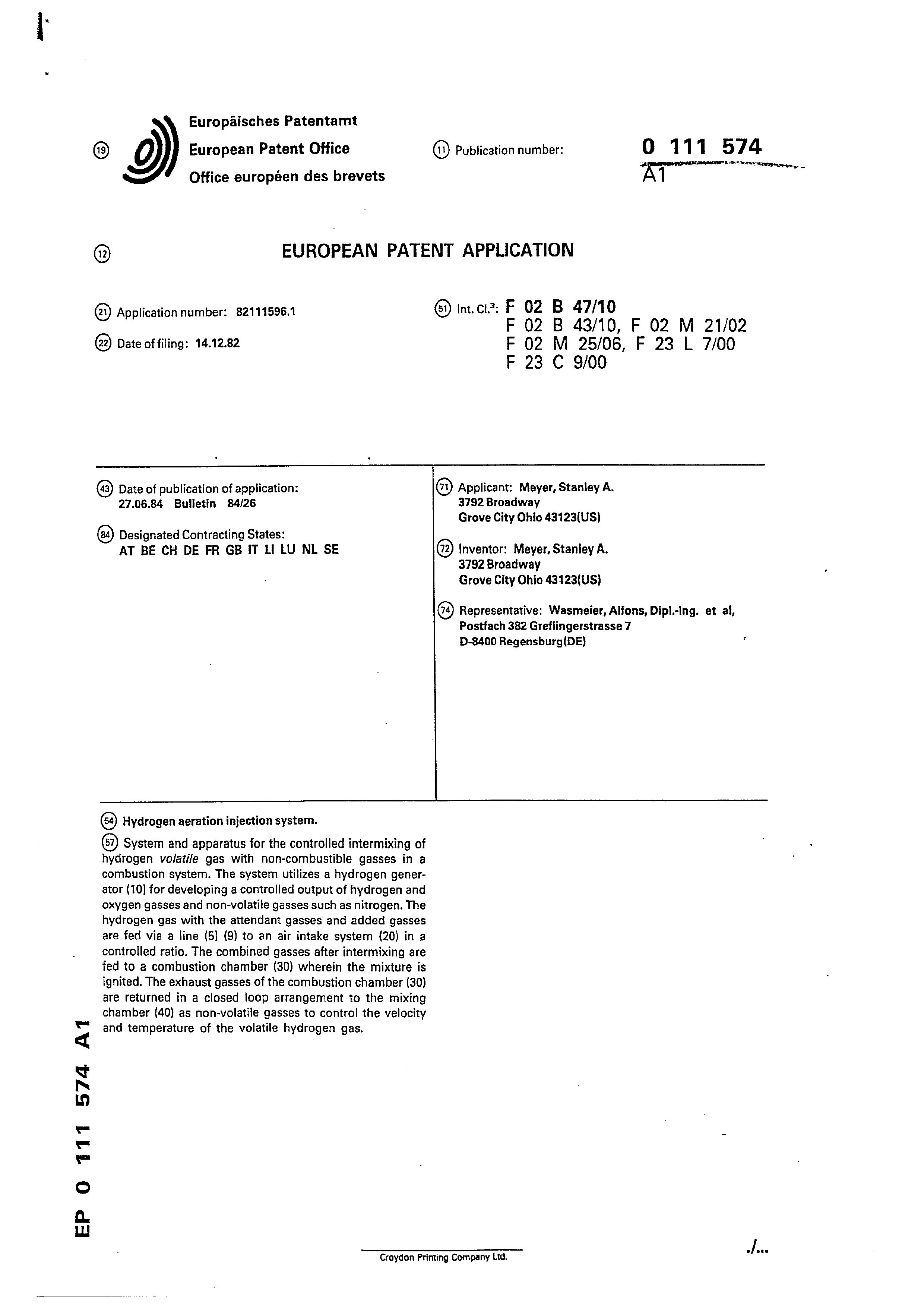
@) System and apparatus for the controlled intermixing of hydrogen volatile gas with non-combustible gasses in a combustion system. The system utilizes a hydrogen generator (10) for developing a controlled output of hydrogen and oxygen gasses and non-volatile gasses such as nitrogen. The hydrogen gas with the attendant gasses and added gasses are fed via a line (5) (9) to an air intake system (20) in a controlled ratio. The combined gasses after intermixing are fed to a combustion chamber (30) wherein the mixture is ignited. The exhaust gasses of the combustion chamber (30) are returned in a closed loop arrangement to the mixing chamber (40) as non-volatile gasses to control the velocity and temperature of the volatile hydrogen gas.
Croydon Printing Company Ltd.
Page 2
Drawing sheet — no readable text.
Page 3
tot
Hydrogen Airdation Injection System
‘| CROSS REFERENCE AND BACKGROUND:
There is disclosed in my co-pending patent application
'| fi1ea September 16, 1981, U.S. Serial Number: 302,807, for a
|; Hydrogen Generator, a generating system converting natural water into hydrogen and oxygen gasses. In that system and method,
the hydrogen atoms are disassociated from a water molecule by the application of a non-regulated, non-filtered, low-power, direct current voltage electrical potential applied to two non-oxicizing ii similar metal plates having water passing therebetween. The
‘ sub-atomic action is enhanced -by pulsing the non-regulated and | i non-filtered direct current voltage. Particularly significanc
iwith m hydrogen generator disclosed in my co-pending applicaticn : y hycrogen g p & @pp
-is that the hydrogen/oxygen generated is in quantity in excess ; of that necessary for practical utilization. Further, and equally! ‘| Significant is that the generation of the hydrogen/oxygen is
controlled by any one of or more of several factors, i.e. varying
voltage, varying pulse rate, varying spacing between plates, switching the number of plates, and plate configuration.
Therefore, the hydrogen/oxygen generation is a demand Ssys-
'cem; that is, the hydrogen/oxygen is generated only upon the i|need. Then, the generation is controlled in quantity by the need;
;, Such as, accelerator for an automotive device. |
Page 4
Ito
i! In my co-pending application filed May 5, 1981, U.S
Serial Number: 262,744, for a Hydrogen Airdation Processor, nonvolatile and non-combustible gasses are controlled in 4 mining
| stage with a volatile gas. The hydrogen ‘airdation processor
system utilizes a rotational mechanical gas displacement system
‘l to transfer, meter, mix, and pressurize the various gasses. In
i! the gas transformation process, ambient air is passed through an | open flame gas-burner system to eliminate gasses and other pre- ‘sent substances. Thereafter the non-combustible gas-mixture is cooled, filtered for impurity removal, and mechanically mixed
‘iwith a pre-determined amount of hydrogen gas. There results a
new synthetic gas. The synthetic gas formation also volume
|meters and determines the proper gas-mixing ratio for establish-
ing the desired burn-rate of hydrogen gas.’ The rotational mechanical gas displacement system in that process determines the
‘; vo lume- amount of synthetic gas to be produced.
The above-noted hydrogen airdation processor, of my co-
pending patent application, is a multi-stage system having util-
‘tem of my other mentioned co-pending application does disclose
La very simple and unique hydrogen generator.
wn ee eee ee tee
ity in special applications. Whereas the hydrogen generator sys-
Page 5
: SUMMARY OF INVENTION:
: The system of the present invention in its most preferred embodiment is for a combustion system having utility in a mechanical drive systém. Particularly in one instance to drive ¢ piston in an automotive device. The system utilizes the hydroger
generator of my co-pending patent application, Serial Number:
302,807, for developing hydrogen gas, and other non-volatile gasses such as oxygen and nitrogen. The hydrogen gas with the attendant non-volatile gasses in a controlled ratio are fed via a line to a controlled air intake system. The combined hydro non-volatile gasses, and the air after inter-mixing are fed to @ ‘combustion chamber wherein the mixture is ignited. The exhzust gasses of the combustion chamber are returned in a closed lcop arrangement to the mixing chamber for the mixture of volatile as the non-combustible gasses. More specifically, the generated
.j hydrogen gas is fed to a gas mixing chamber, wherein the hydrcege
| Bes {s inteér-mixed with non-combustible gasses. The mixture is
|| fed to a carburator (air-mixture) system. The gas mixture is fed through nozzle to chamber in a jet
|) spray. Valve or gate controls the amount of air intake to the “jet spray. The gas combines with the air to form a gas mix-
" ture of hydrogen, non-volatile gas, and oxygen. The mixture, now combustible, but not volatile, is entered into a-combusticn '! chamber conventional in design and comprising a cylinder capebie Ve withstanding high pressure. At the uppermost end of coz-
! pustion chamber is a spark plug igniter..
Page 6
ti In a controlled manner, relative to the piston stroke, the | spark ignition via plug, causes the mixed gasses to combust,
1 The compression caused by the combustion, forces the piston to push downwardly in the cylinder.
The exhaust gasses, the residue of the combustion, now
comprise a non-combustible mixture. These exhaust gasses cre ijfed to the gas mixing chamber as the non-combustible gasses in
a closed loop arrangement.
Page 7
1 || OBJECTS:
3 It is accordingly a principal object of the present invention
4 il to provide a combustion system of gasses combined from a source |
5 || of volatile and non-combustible gasses.
6 | Another object of the invention is to provide such a com-
a. 7 ;, bustion system that utilizes hydrogen’ as the volatile gas and the | 8 |, exhaiist of the combustion system as. the non-combustible gas.
9 i A further object of the invention is to provide such a coz-
10 | bustion system that may be incorporated in a mechanical crive
| ‘Still other objects and features of the present invention will become apparent from the following detailed description |
14 |: when taken in conjunction with the drawings in which:
15 :! BRIEF DESCRIPTION OF DRAWINGS:
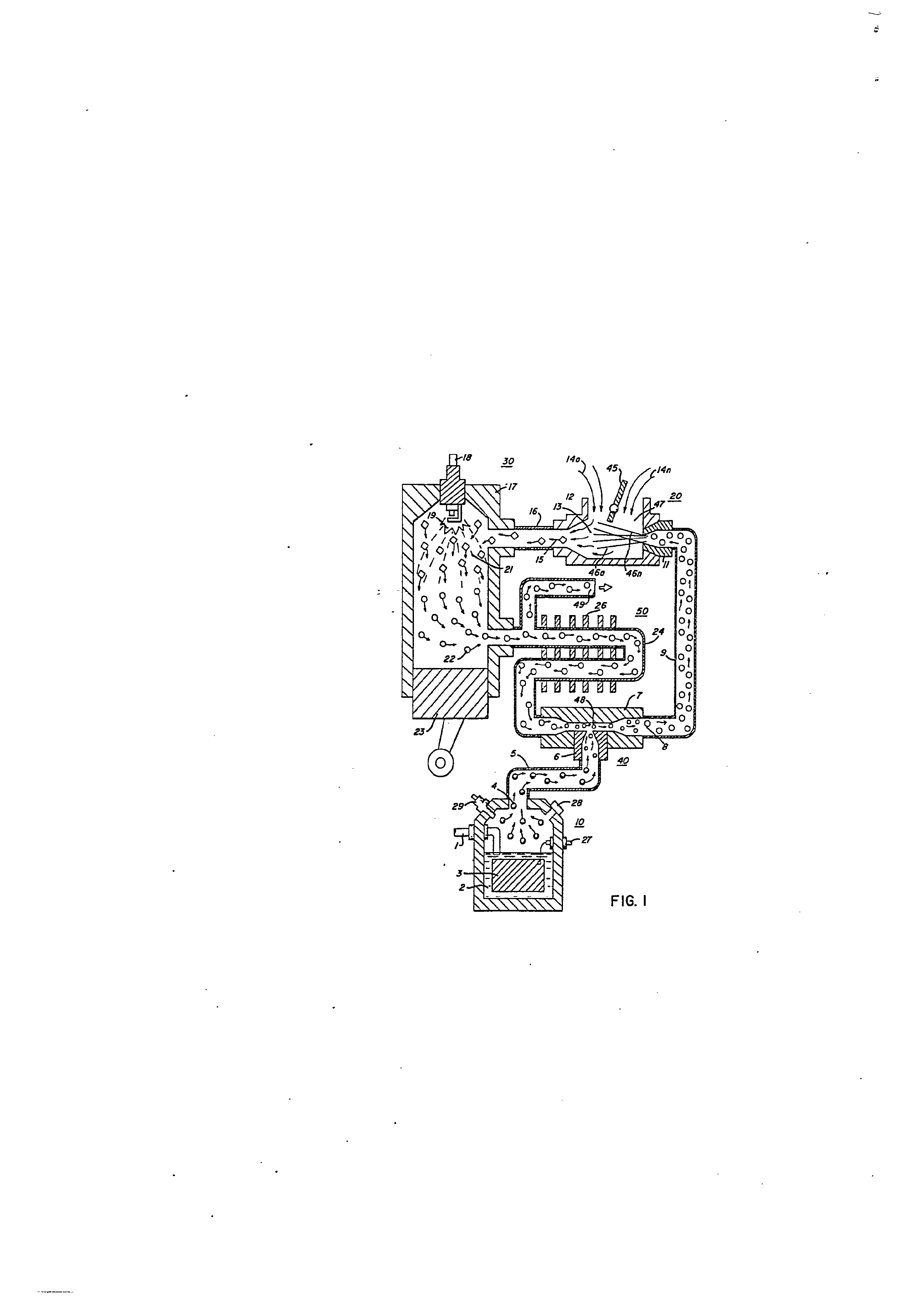
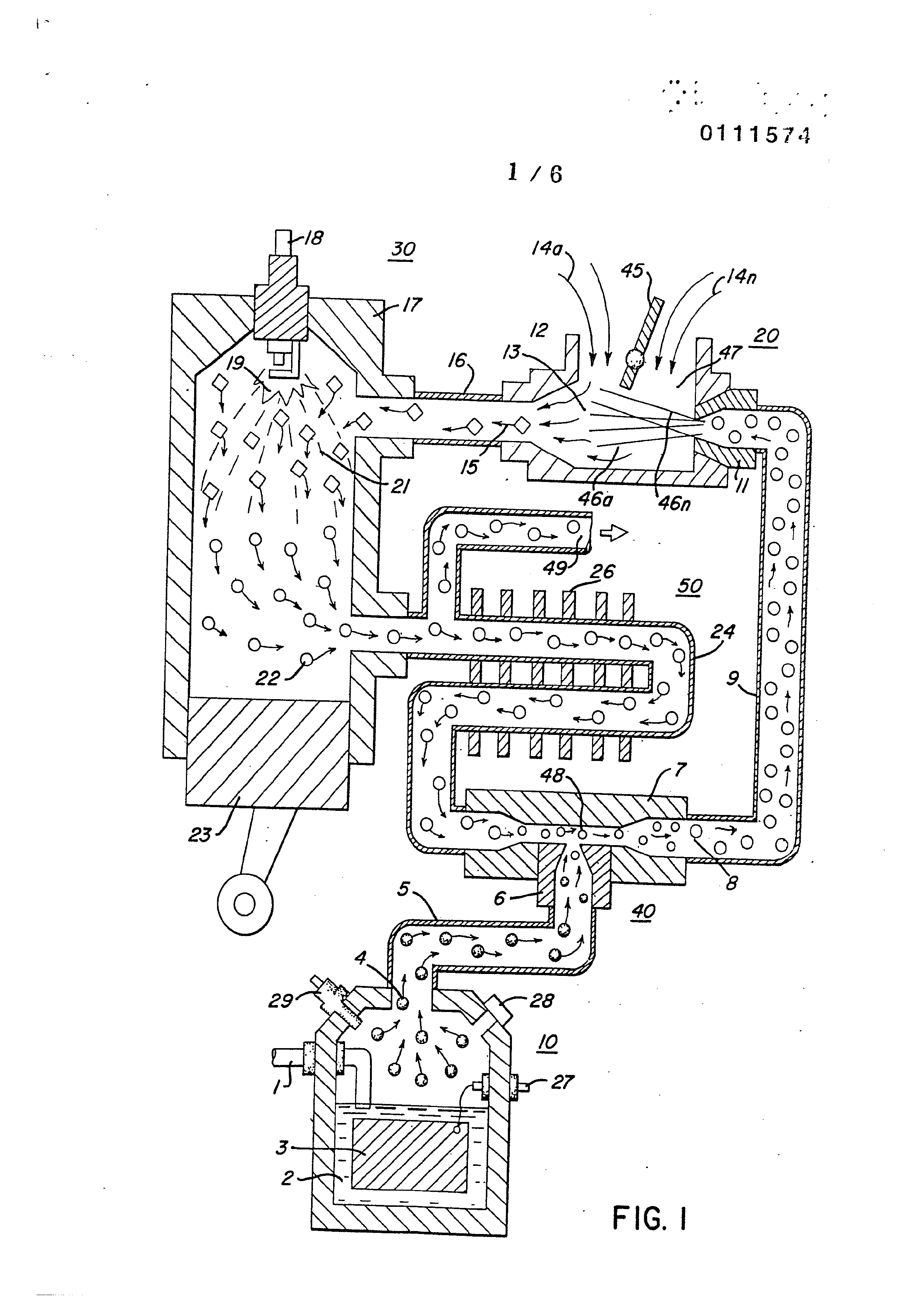
16 . Pigure 1 is a crossectional mechanical schematic iliustrs- 17 \; tion of the present invention in its most preferred embodimern:.
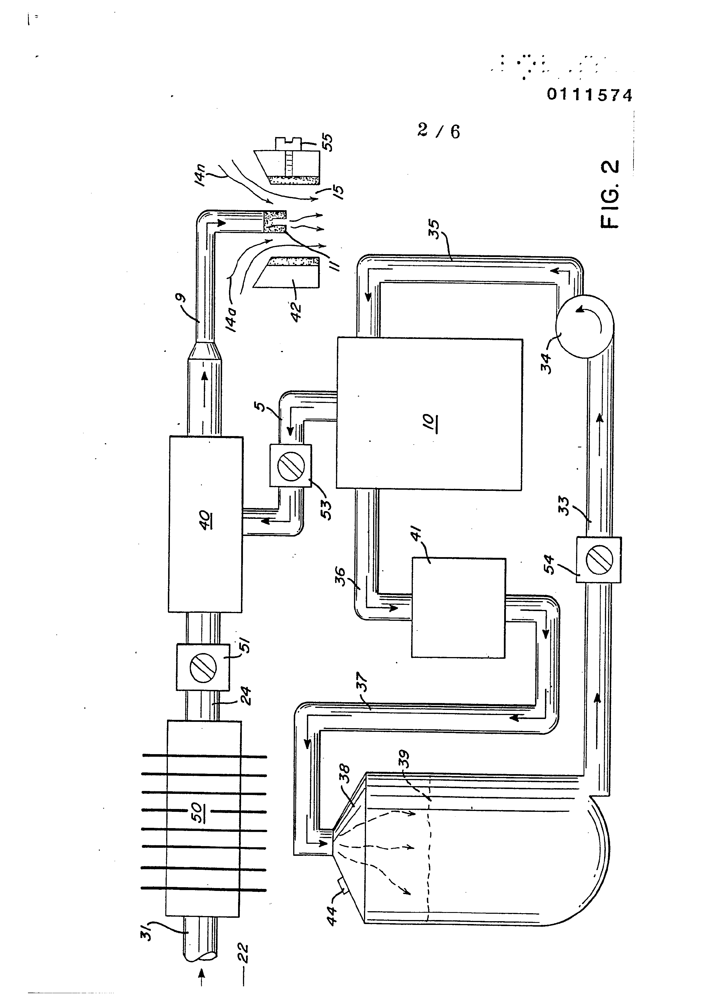
1B! Figure 2 is a block schematic illustration of the preferred
19 itembodiment of Figure 1.
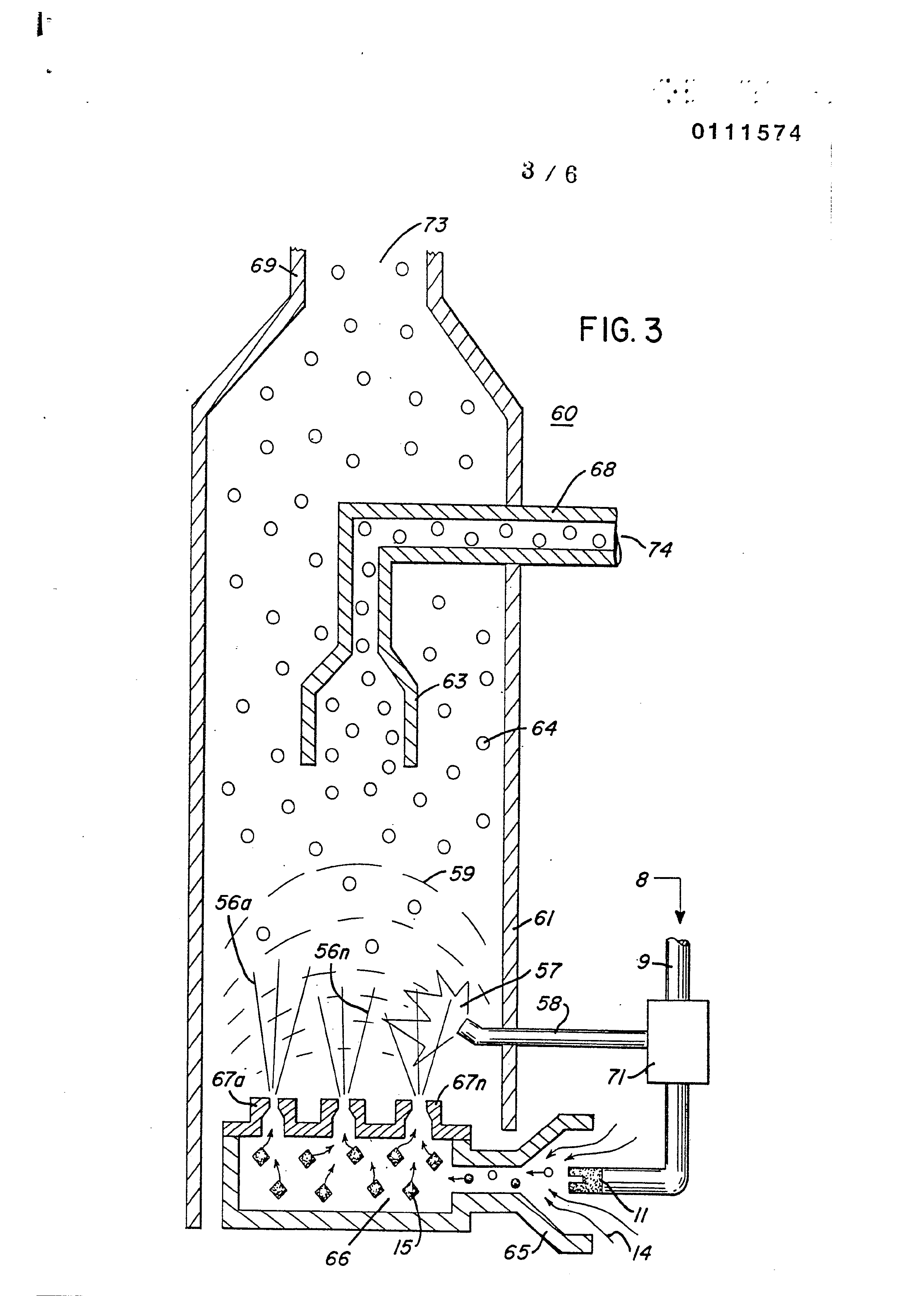
20 4} Figure 3 is an alternative gas system replacement for that i
21 i;shown in Figure 1,
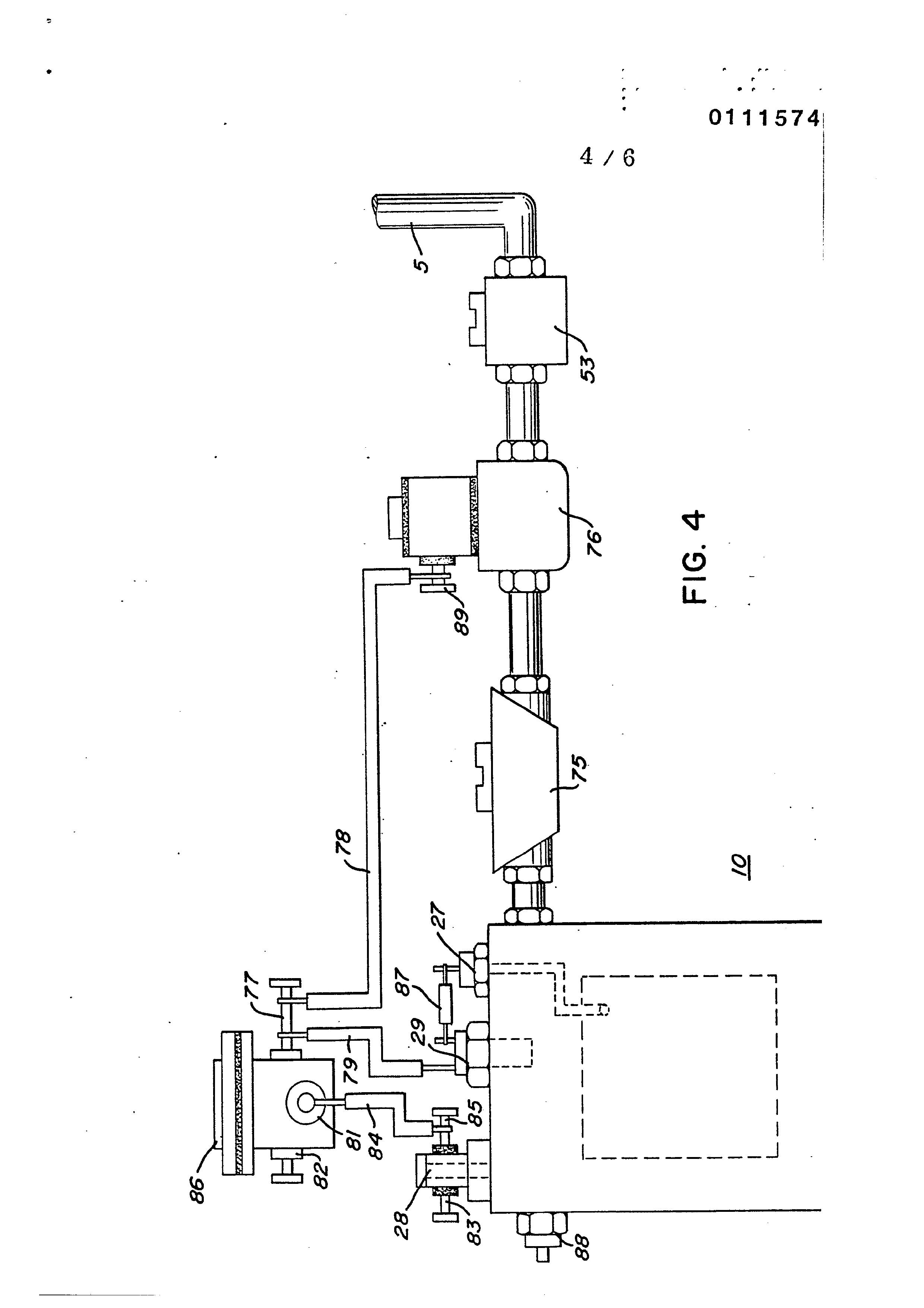
22 Figure 4 is a block schematic illustration of a complete
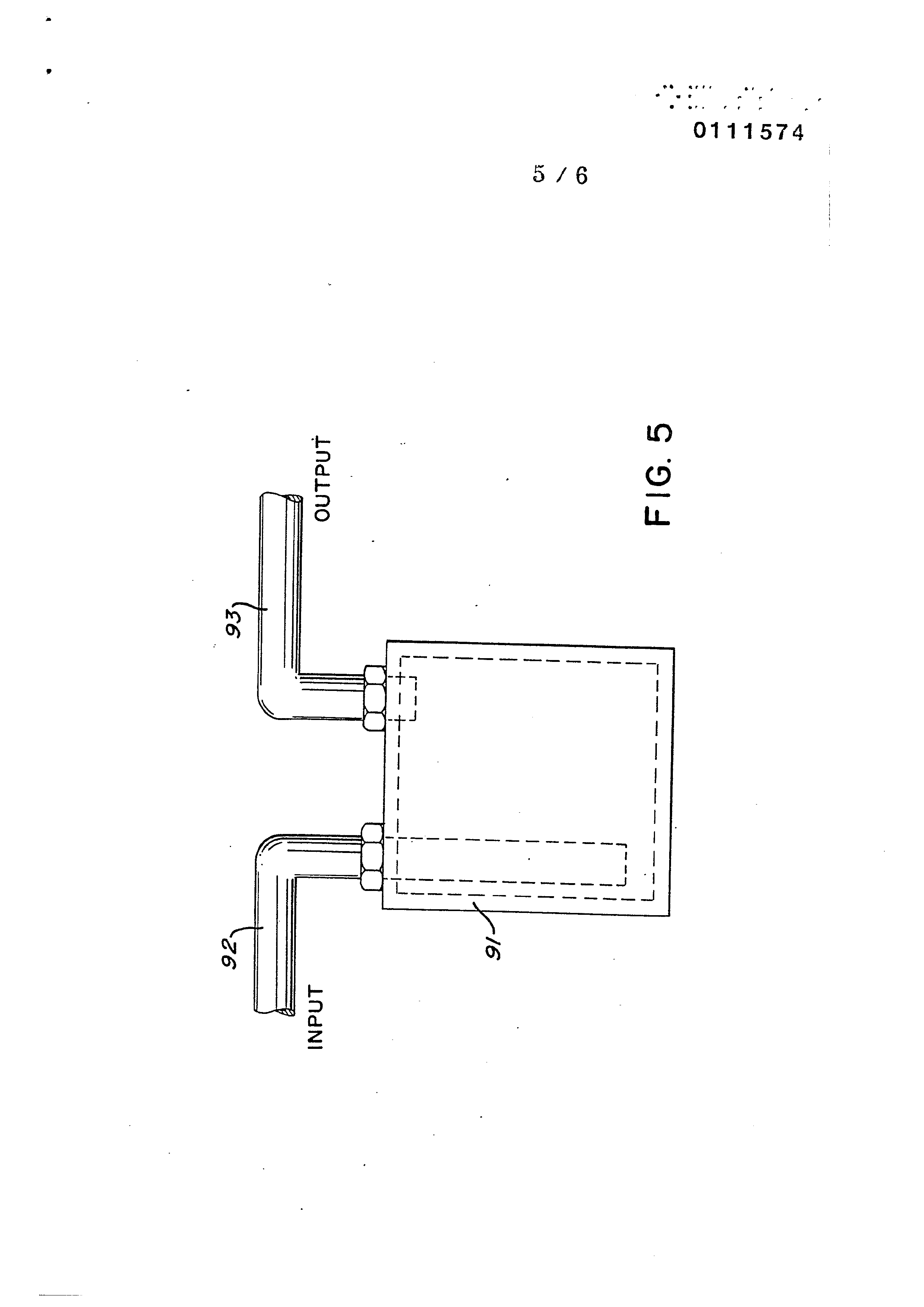
23 | drive system utilizing the concepts of the present invention. ; 24 : Figure 5 is a further application of the present .inventizcn
75 .,in a regenerative energy feedback system.
Page 8
DETAILED DESCRIPTION OF INVENTION TAKEN WITH DRAWINGS:
“Referring particularly to Figure 1 the complete overall conbustion system is illustrated together with a mechanically driven piston. Similarly, Figure 2 illustrates the complete system in ; its preferred embodiment.
With particular reference to Figure 1, the hycrogen source
j 10.is the hydrogen generator disclosed and described in ny co- !-pending application, supra. The container 102 is an enclosvre for | a natural water bath 2. Immersed inthe water 2 is an array of ; plates 3 of similar non-oxidizing material. Applied to plates
3 isa source of pulsed direct current potential via electrical inlet 27. The action of the pulsed direct current, a voltage/ current potential, on the plates causes the hydrogen and oxygen atoms to become disassociated from the water molecule. in that the action is a sub-atomic action and not a chemical action any water irrespective of source may be utilized.
Varying either the potential of the direct current source or the pulse rate of the pulsing of the direct current potential will vary proportionately the generation of the hydrogen/oxygen. Other factors are disclosed for varying the output of the gener-
ator. To replenish the expended water the generator provides a
continuous water source l.
Ma eee ee me eee 8 ee em ees ep e
Page 9
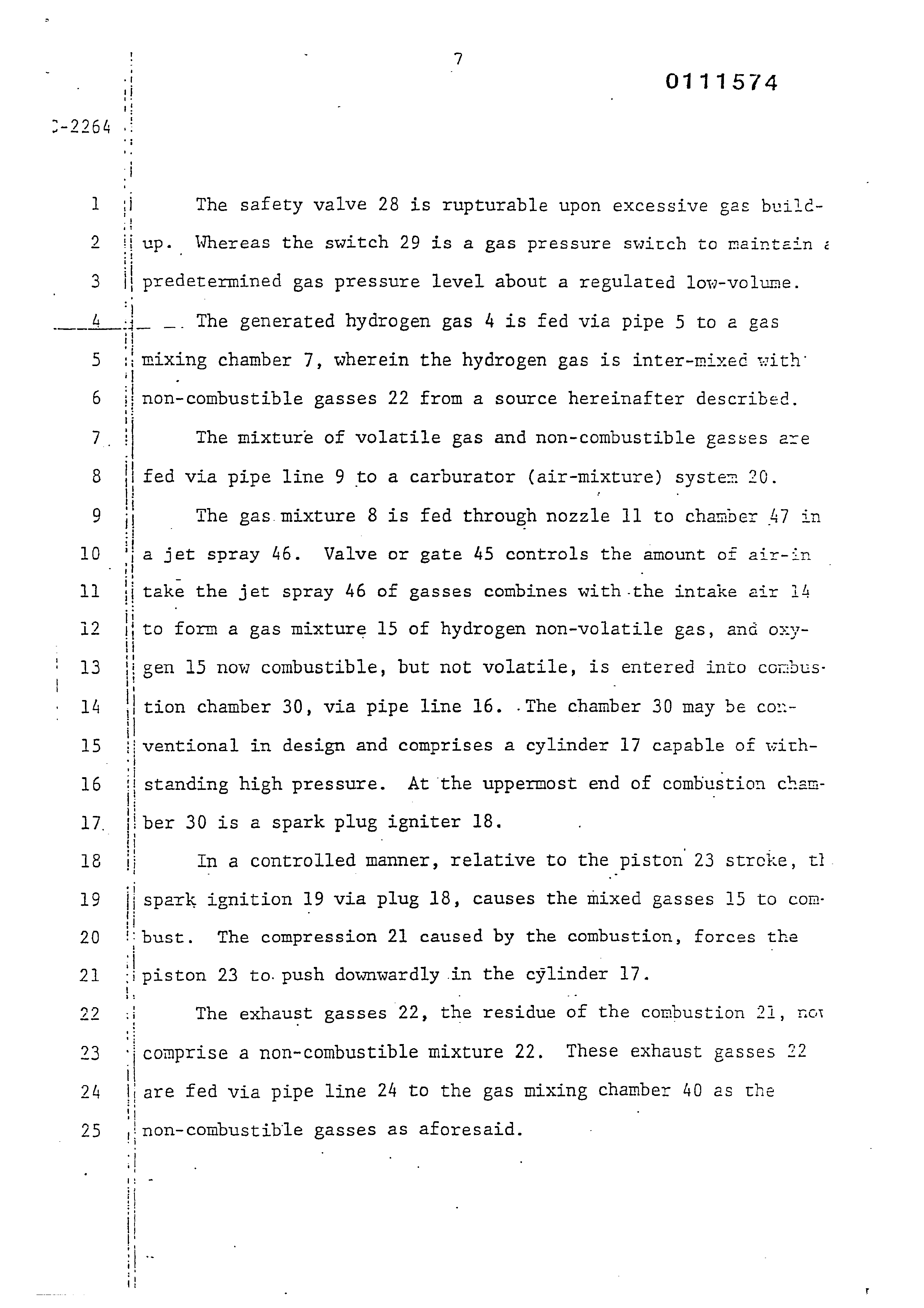
The safety valve 28 is rupturable upon excessive gas bvildup. Whereas the switch 29 is a gas pressure switch to maintain
ii predetermined gas pressure level about a regulated low-volume.
i _. The generated hydrogen gas 4 is fed via pipe 5 to a gas
'| non- combustible gasses 22 from a source hereinafter described : The mixture of volatile gas and non-combustible gasses are | fed via pipe line 9 to a carburator (air-mixture) system 20. ( The gas. mixture 8 is fed through nozzle 11 to chamber 47 in
a jet spray 46. Valve or gate 45 controls the amount of air-
to form a gas mixture 15 of hydrogen non-volatile gas, and oxy-
;| take the jet spray 46 of gasses combines with-the intake air i4
I eon chamber 30, via pipe line 16. .The chamber 30 may be con-
iiventional in design and comprises a cylinder 17 capable of withii standing high pressure. At the uppermost end of combustion chan-
ber 30 is a spark plug igniter 18.
ii spark ignition 19 via plug 18, causes the mixed gasses 15 to con:
i bust. The compression 21 caused by the combustion, forces the
| piston 23 to. push downwardly in the cylinder 17.
: The exhaust gasses 22, the residue of the combustion 21, not | comprise a non-combustible mixture 22. These exhaust gasses 22
|| are fed via pipe line 24 to the gas mixing chamber 40 as the
‘non-combustible gasses as aforesaid.
igen 15 now combustible, but not volatile, is entered into combus-
In a controlled manner, relative to the piston 23 strceke, tl.
Page 10
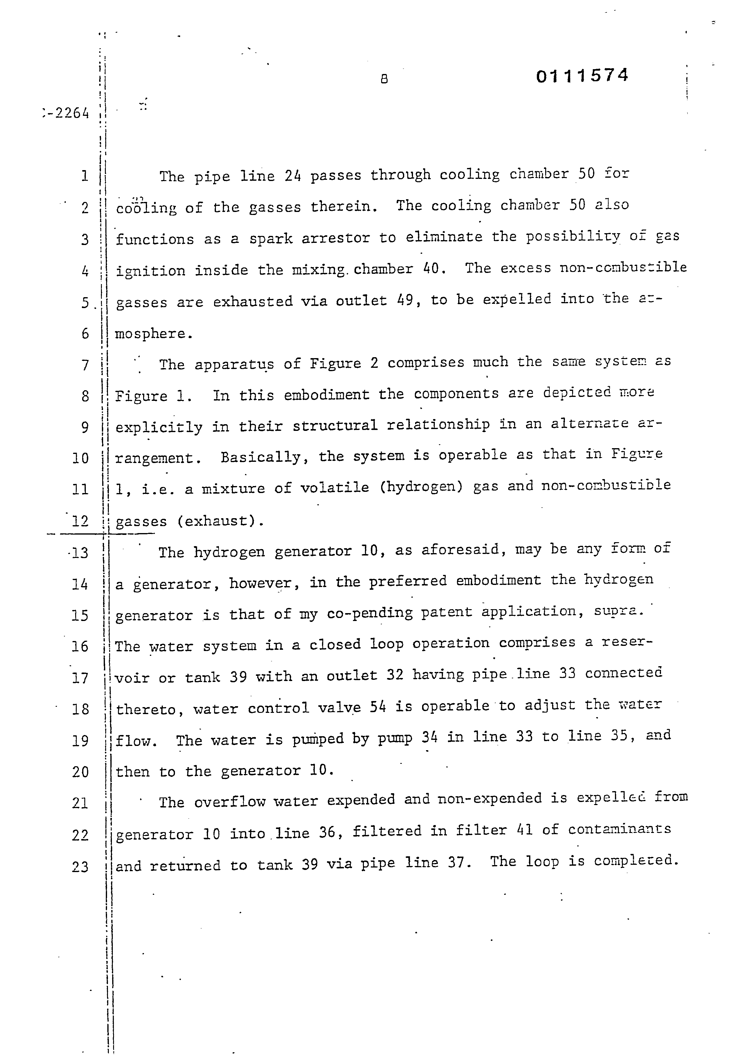
The pipe line 24 passes through cooling chamber 50 for | cooling of the gasses therein. The cooling chamber 50 also functions as 2 spark arrestor to eliminate the possibility of gas ignition inside the mixing, chamber 40. The excess non-combustible gasses are exhausted via outlet 49, to be expelled into the azmosphere.
The apparatus of Figure 2 comprises much the same system és
Figure 1. In this embodiment the components are depicted more
explicitly in their structural relationship in an alternate ar-
rangement. Basically, the system is operable as that in Figure
1, i.e. a mixture of volatile (hydrogen) gas and non-combustible
gasses (exhaust).
The hydrogen generator 10, as aforesaid, may be any form of a generator, however, in the preferred embodiment the hydrogen generator is that of ny co-pending patent application, supre. | The water system in a closed loop operation comprises a reser~ ivoir or tank 39 with an outlet 32 having pipe line 33 connected thereto, water control valve 54 is operable to adjust the water ; flow. The water is pumped by pump 34 in line 33 to line 35, and then to the generator 10.
The overflow water expended and non-expended is expellec from
jgenerator 10 into line 36, filtered in filter 41 of contaminants
and returned to tank 39 via pipe line 37. The loop is complezed.
Page 11
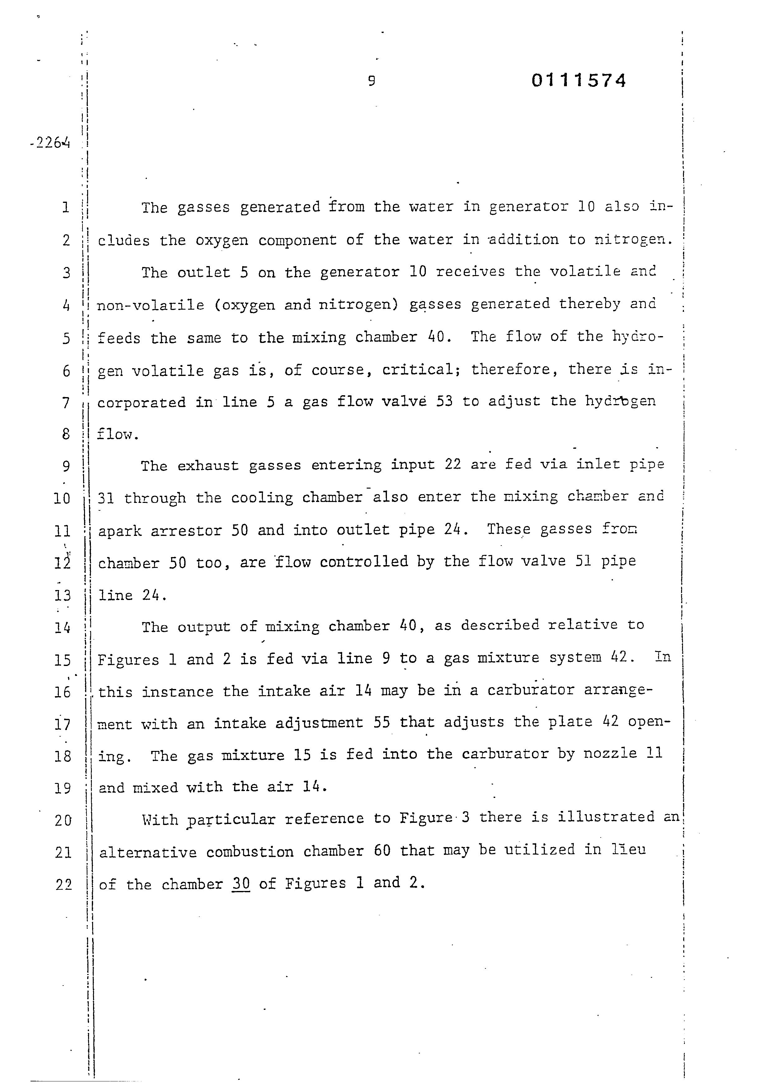
The gasses generated from the water in generator 10 also includes the oxygen component of the water in addition to nitrogen.
The outlet 5 on the generator 10 receives the volatile anc non-volatile (oxygen and nitrogen) gasses generated thereby and feeds the same to the mixing chamber 40. The flow of the hydro-
corporated in line 5 a gas flow valvé 53 to adjust the hydrogen flow.
The exhaust gasses entering input 22 are fed via inlet pipe 31 through the cooling chamber also enter the mixing chamber and apark arrestor 50 and into outlet pipe 24. These gasses fron chamber 50 too, are flow controlled by the flow valve 51 pipe
The output of mixing chamber 40, as described relative to
Figures 1 and 2 is fed via line 9 to a gas mixture system 42. In
‘this instance the intake air 14 may be in a carburator arrange-
ment with an intake adjustment 55 that adjusts the plate 42 open-
ing. The gas mixture 15 is fed into the carburator by nozzle 11
‘land mixed with the air 14.
With particular reference to Figure 3 there is illustrated an:
alternative combustion chamber 60 that may be utilized in lieu
of the chamber 30 of Figures 1] and 2.
gen volatile gas is, of course, critical; therefore, there is in- !
Page 12
ion
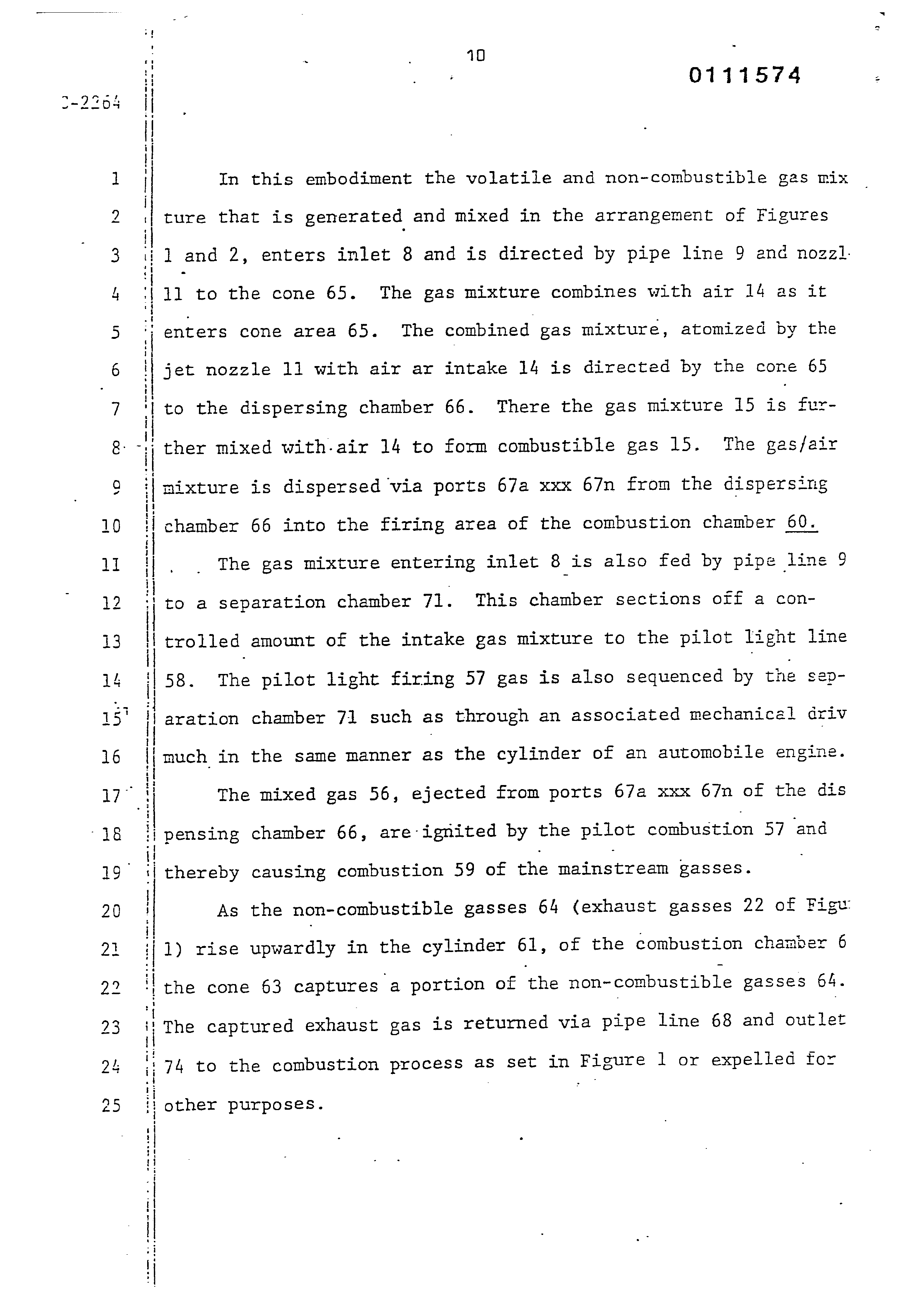
In this embodiment the volatile and non-combustible gas mix ture that is generated and mixed in the arrangement of Figures 1 and 2, enters inlet 8 and is directed by pipe line 9 and nozzl.
11 to the cone 65. The gas mixture combines with air 14 as it
‘enters cone area 65. The combined gas mixture, atomized by the
jet nozzle 11 with air ar intake 14 is directed by the cone 65 to the dispersing chamber 66. There the gas mixture 15 is further mixed with-air 14 to form combustible gas 15. The gas/air mixture is dispersed via ports 67a xxx 67n from the dispersing chamber 66 into the firing area of the combustion chamber 60.
The gas mixture entering inlet 8 is also fed by pipe line 9 to a separation chamber Jl. This chamber sections off a controlled amount of the intake gas mixture to the pilot light line 58. The pilot light firing 57 gas is also sequenced by the separation chamber 71 such as through an associated mechanical driv much in the same manner as the cylinder of an automobile engine.
The mixed gas 56, ejected from ports 67a xxx 6/n of the dis pensing chamber 66, are ignited by the pilot combustion 57 and thereby causing combustion 59 of the mainstream gasses.
As the non-combustible gasses 64 (exhaust gasses 22 of Figu: 1) rise upwardly in the cylinder 61, of the combustion chamber 6 the cone 63 captures a portion of the non-combustible gasses 64. The captured exhaust gas is returned via pipe line 68 and outlet
74 to the combustion process as set in Figure 1 or expelled for
other purposes.
Page 13
ad i. The major purpose of the non-combustible gasses 64 by-pass <2 the cone 63 and rise further to the outlet exhaust 69 and are 3 expelled at opening 73. - uh . In the constructed arrangement of Figure 4, there is illus 5 T | trated a gas control system that may be retrofitted to an exis- 6 ting automobile internal combustion engine without changing or
7 modifying its design parameters or characteristics.
Page 14
jjoperation, the process mixture is ignited much in the same marner
As low-voltage direct current is applied to Satety valve 28, | solenoid 86 is activated. The solenoid applies a control voltage to the hydrogen generator plates 26 via terminal 27 through pressure switch 29. As the electrical power activates electric solenoid 86, hydrogen gas is caused to pass through flow adjustment‘ valve 33 and then outlet pipe 5 for utilization.
Gas regulator valve 75 is utilized to reduce the pressure
level inside the hydrogen generator 10. The pressure differential
hydrogen gas output.to gas mixing chamber 40 is, for example, 30 ibs. to 15 lbs. Once hydrogen generator 10 reaches an optissum gas pressure level, pressure switch 29 shuts off electrical power to the hydrogen exciters. If the chamber pressure exceeds a predetermined level, thé safety release valve 28 is activated disconnecting the electrical current and thereby shutting down the entire system for safety inspection.
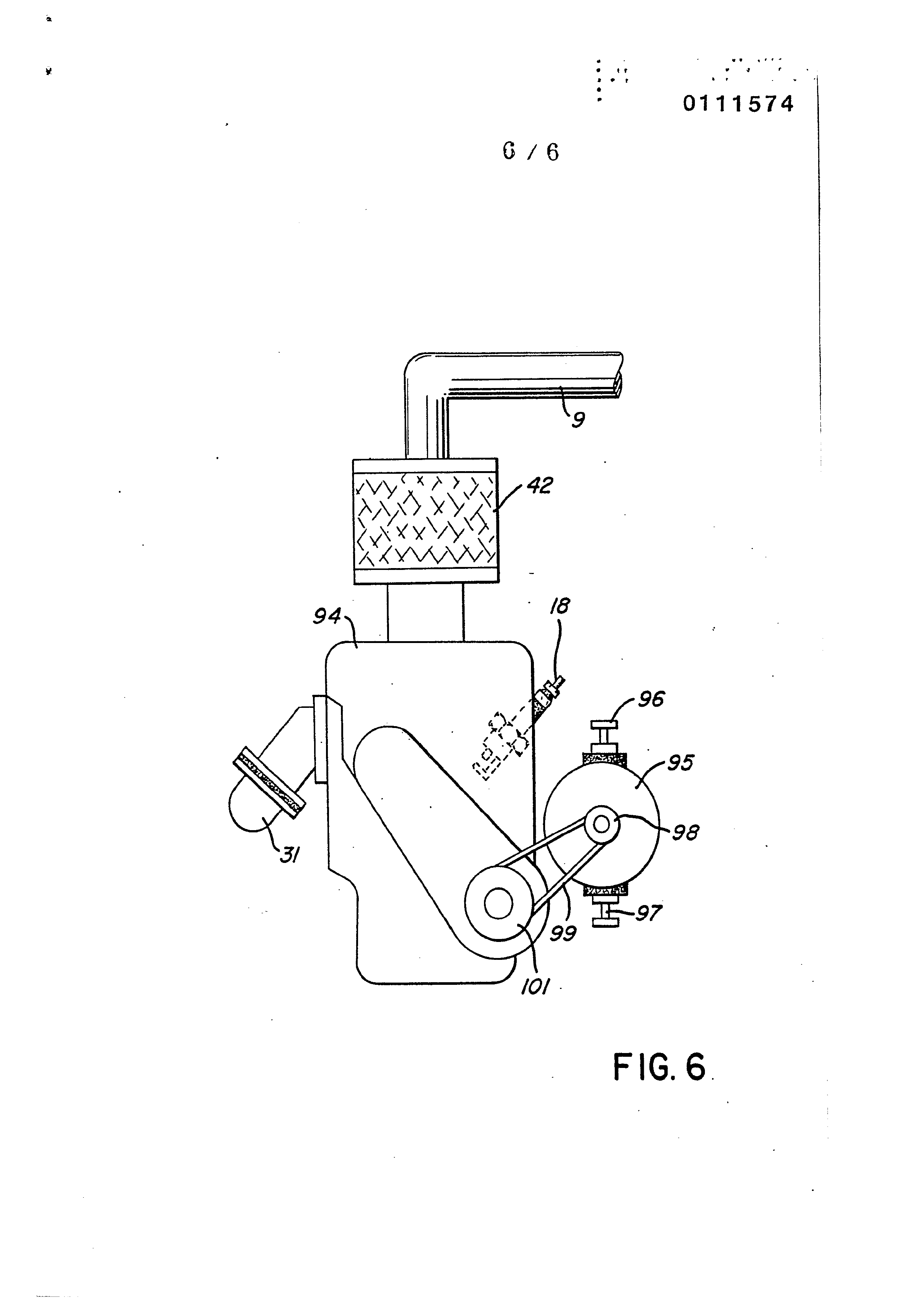
"Similar to an automobile engine or other drive force re-. quiring an electrical energizing source, the present invention may include the regenerative energy feedback arrangement shown in Figure 6. - . i
The process utilizes a mechanical drive system as cescribed relative to Figures 1 and 2; and which mechanical drive mav be
that of a piston such as utilized in a gasoline engine. In
as in Figure 1. The drive mechanism in turn activates electrical
lgenerator and utilized as the firing voltage on the spark plug
18; again, in a closed loop arrangement.
Page 15
gasses, it is completely irrelevent as to the nature ‘of the
Further, as aforesaid in my co-pending application, the
Hydrogen-Generator utilizes an electrical direct current voltage
source-on the energizer plates. In addition to the feed back
closed loop as set forth with respect to the ignition system,
the feedback system of Figure 6 is equally, and perhaps more
significantly, applicable to the process of the hydrogen generator That is, again referring to Figure 1, the electrical voltage app=
lied to contact 27 is in the closed loop with the alternatoz/
mechanical drive of Figure 6. In this way, the voltage reguirethents -for the hydrogen generator are drastically ‘reduced.
In the description of the-embodiments illustrated in the several Figures of the drawings, the terms non-combustible, and non-volatile were used interchangeably. It is intended that there be no distinction. Further, relative to the non-combustible gasseS ... the requirement being that it be non- -combustible.
Depending upon the utility of the combustion chamber, the ratio of the highly volatile hydrogen gas and the non-voletile gas controls the combustion rate. Further, as understood oxygen is required for combustion, and oxygen is entered into the gas mixture line by the air intake. Again, the ambient air is under~- stood to contain many and variable gasses other than oxygen. Accordingly air- -intake will add non-combustible gasses to the gas mixture. This may require that the non-combustible gas ir- |+
take be varied .
. . and in some instances may not be necessary
Page 16
In THE CLAIMS:
1. A combustion system comprising:
a hydrogen/oxygen generator,
a housing having a water reservoir for retaining natural water
ctherin and a gas collection chamber maintaining a preset volune
of gas under pressure, ~ Ot |
a pair of similar non-oxidizing plates positioned in said water
a direct current voltage source connected to said plates to isassociate the hydrogen atoms and oxygen atoms from said
water molecules, and
a gas mixing chamber,
piping means including a control ‘valve connecting the hydrogen gas from said hydrogen source to said mixing chamber,
a source of non-volatile gas,
piping means for including a control valve connecting the non-
volatile gas from said non-volatile source to said mixing
chamber,
said first and second “named control valves regulating the gas
mixture ratio output from said mixing means,
air-intake means connected to the output of said mixing chamber
for combining air with said mixed gases, .
a gas burner having said controlled amount of mixed gases from said mixing chamber and from said air-intake means fed thereto,
means for igniting said gas/air mixture in said gas burner,
2. The combustion system of Claim 1 wherein said air-intake means
further comprises a valve for controllingthe amount of air—intake
to said mixed gases.
3. The combustion system of Claim 1 wherein said means to ignite said gas/air mixture is a combustion chamber having an ignitor.
4. The combustion system of Claim 3 further including a drive mechanism disposed relative to said combustion chamber and wherein said drive mechanism is responsive to said gas burning.
Page 17
5. The combustion system of Claim 4% wherein said combustion chamber further comprises outlet means for expelling the exhaust gases therefrom, and means for returning a portion of said exhaust gases to said mixing means.
6. The combusteion system of Claim 4 wherein said hydrogen
_: " source is a hydrogen generator.
7. The combustion system of Claim 1 wherein said hydrogen source
is a hydrogen reservoir.
8. The combustion system of Claim 3, further including a pilot chamber and means for directing a portion (8) of said gas/air mixture thereto, . means (58) of connecting said pilot chamber to said combustion chamber, and
means to ignite said gas/air mixture portion to provide a pilot ignition (57) to said combustion chamber (60).
9. The combustion system of Claim 3 wherein said means to ignite said mixed gases comprises an electrical ignition means and 4 source of electrical energy.
10. The combustion system of Claim 3 wherein said combustion
chamber comprises a mixed gas/air dispersing chamber having a series of ports therein.
11. The combustion system of Claim 4 further including utilization means and means for connecting said drive mechanisn thereto.
1l2. The combustion system of Claim 4 further comprising a source o- electrical energy connected to said ignitor in a closed loop mechanical arrangement with said drive mechanisn.
13. The combustion system of Claim 5 wherein said mears for returning a portion of said exhaust gases to said mixing Beans
Page 18
further includes cooling means for cooling said exhaust gases.
14, The combustion system of Claim 5 wherein said means for returning a portion of said exhaust gases to said mixing means further includes a spark arrestor for preventing uncontrolled combustion.
15. The combustion system of Claim 6 wherein said hydrogen generator includes a source of electrical potential, and wherein said source of electrical potential is connected is a closed
loop mechanical arrangement with said drive mechanism.
Page 19
Drawing sheet — no readable text.
Page 20
Drawing sheet — no readable text.
Page 21
Drawing sheet — no readable text.
Page 22
Drawing sheet — no readable text.
Page 23
Drawing sheet — no readable text.
Page 24
Drawing sheet — no readable text.
Page 25
Office
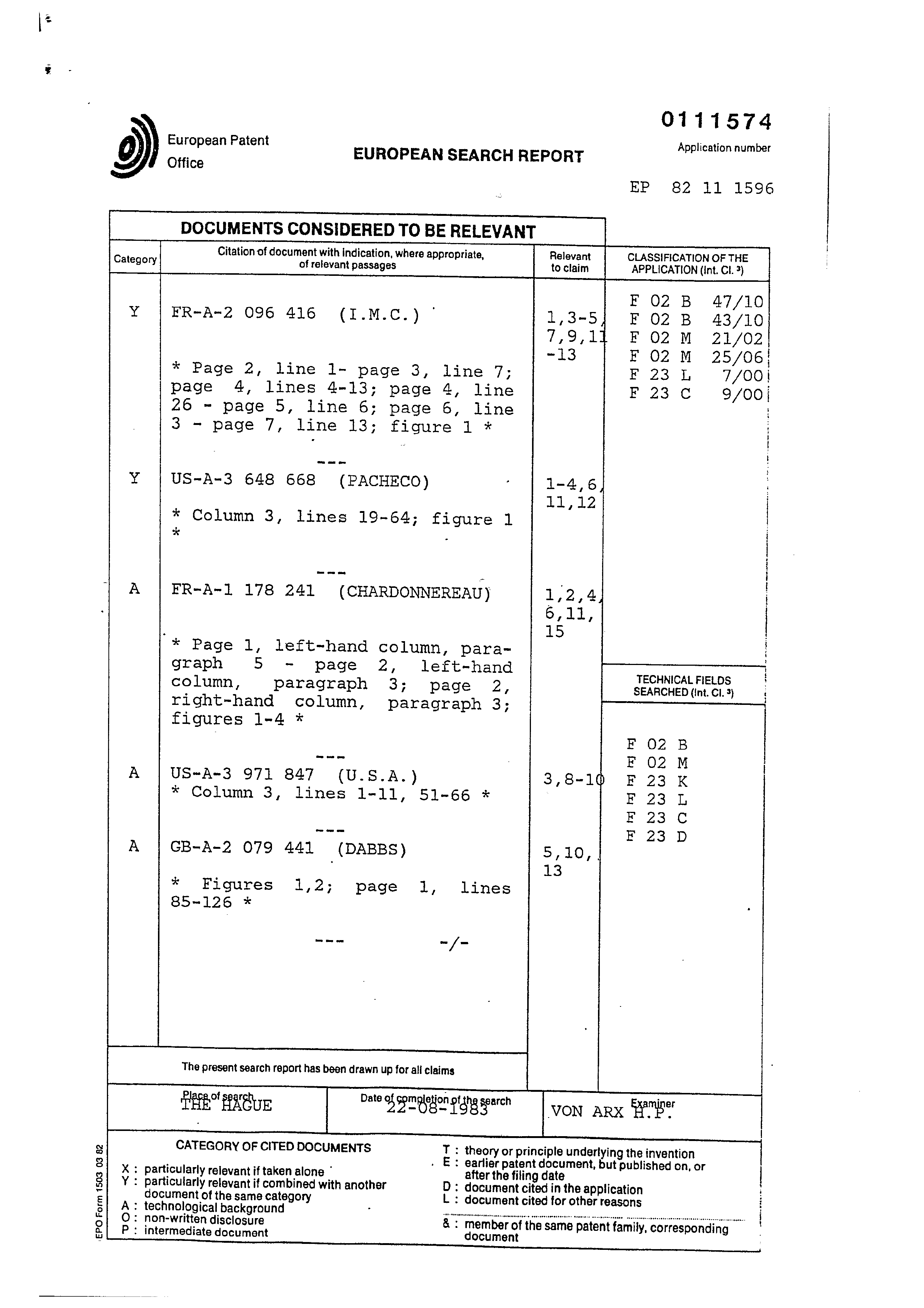
EUROPEAN SEARCH REPORT
DOCUMENTS CONSIDERED TO BE RELEVANT
Application number
Citation of document with indication, where appropriate,
Relevant
CLASSIFICATION OF THE
Category of relevant passages to claim APPLICATION (Int. Cl. 3)
* Column 3, lines 19-64; figure 1
* Page 1, left-hand column, para- i graph 5 - page 2, left-hand TECHNICALFIELDS = column, paragraph 3; page 2, SEARCHED (int. Cl. 3} right-hand column, paragraph 3; figures 1-4 *
aaked F 02M
* Figures 1,2; page 1, lines
The present search report has been drawn up for all claims THE Pkt ur Preparer sgg ct | von ARK Bene CATEGORY OF CITED DOCUMENTS T : theory or principle underlying the invention . . . E: earlier patent document, but published on, or X : particularly relevant if taken alone after the filing date Y : particularly relevant if combined with another D : document cited in the application document of the same category L : document cited for other reasons A: technological background <ituntnenteeascannanes samaane tte a . 9 : non-written disclosure & : member of the same patent family, corresponding
: intermediate document document
Page 26
‘*) European Patent Office
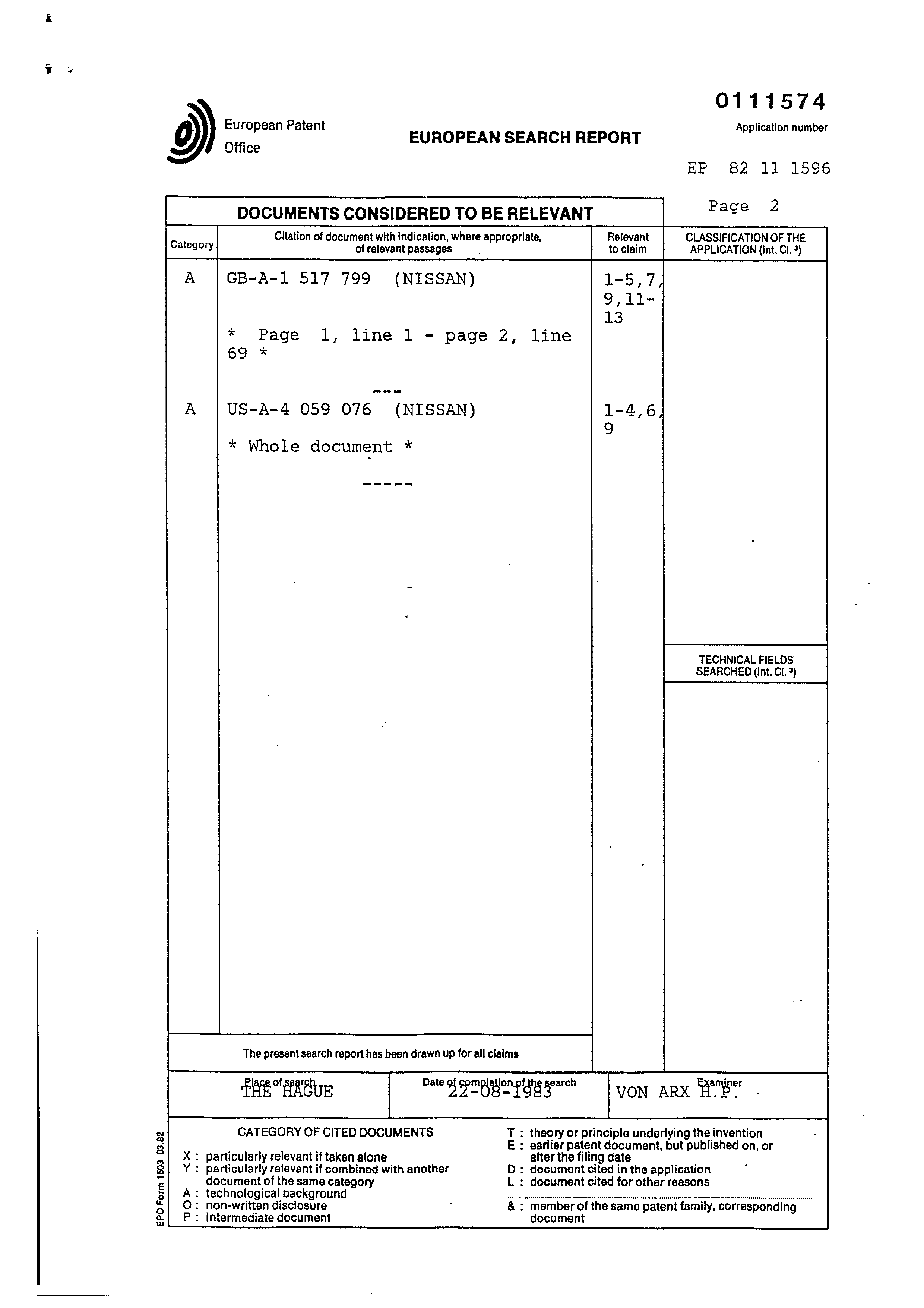
EUROPEAN SEARCH REPORT
Application number
DOCUMENTS CONSIDERED TO BE RELEVANT Page 2 : Citation of document with indication, where appropriate, Relevant CLASSIFICATION OF THE Category of relevant passages to claim APPLICATION (int. Ci. 9)
* Page 1, line 1 - page 2, line
* Whole document *
The present search report has been drawn up for all claims
TECHNICAL FIELDS SEARCHED (Int. Cl. 3)
ries og eneae Tver
VON ARX Hee
CATEGORY OF CITED DOCUMENTS
: particularly relevant if taken alone
: particularly relevant if combined with another document of the sama category
> technological background
: theory or principle underlying the invention
: earlier patent document, but published on, or after the filing date
: document cited in the application
: document cited for other reasons
: non-written disclosure
vOF <x
: member of the same patent family, corresponding : Intermediate document document
Provenance
- Shelf
- Stan Meyer Patents
- Book
- European Patents
- Pages
- 26
- Method
- pdftoppm 300dpi + tesseract 5 (eng)
- Source
- open-source-energy.org patent PDF
- Inventors
- Stanley A. Meyer
- Source
- open-source-energy.org →