report
Electrical polarization process: patent validation report
1 January 1995
Page 16
WFC INJECTOR PLUG
AUTO INJECTOR SYSTEM WFC Memo 420 DA
AVIATION INJECTOR SYSTEM
ROCKET ENGINES APPLICATIONS
WATER FUEL CELL
Document of Records
Electrical Polarization Process
Voltage Intensifier Circuit (VIC)
Copy of Document
Certificate of Registration
Patent Cooperation Treaty (PCT) Act
Natural Water Hydrogen Generation System
The U.S. Government has allowed the WFC Technology of Inventions to go forward into the International Market Place by issuing foreign grant license No. 492680 issued July 10. 1989 and foreign grant license No. 490606 issued Nov. 15, 1989 to Stanley A. Meyer as so specified under U.S. Presidential Executive Order (MPEP 708,02VI ENERGY) in compliance with The Patent Cooperation Treaty (PCT) Act as so mandated under the U.S. War Powers Act. Heavy fines and imprisonment are levied on anyone who falsely claims to have participated in the development of a invention. Under the PCT Treaty Act, a Declaration of Oath must be signed, certified, and registered prior to the filing of any PCT patent application. Notice of "Executive Order To Protect" is hereby invoked immediately under the War Power Act, as confirm and attested by Inventor, Stanley A. Meyer, as "Record of Filing" contained herein, as said "Posting of Records" being presented as Public "Record of Review.".
WATER FUEL CELL
JESUS CHRIST IS LORD
Copyright © 1995 By Stanley A. Meyer
© under UCC 1979 By Stanley A. Meyer
WATER FUEL CELL. 3792 BROADWAY. GROVE CITY. OHIO 43123, 1-614-871-4173: FAX 1-614-871-8075
Page 17
Electrical Polarization Process
Amp Inhibiting Circuit
WEC U.S. Patent Validation Report
Natural Water Hydrogen Generation System
As in reference to attached WFC Patent Validation Report dated January 14, 1983 as per WEC Test-Results “Mode of Operability” of using “Voltage Potential” to dissociate the water molecule (without chemical additives) (called WFC Electrical Polarization Process hereinafter) as so specified under U.S. Patent Office (35 USC 101) to demonstrate operability, the applied Pulse- Voltage Frequency is adjusted to tune-in to the dielectric properties of water by the use of WFC “Amp Inhibiting Circuit” (Figure 8XA) titled WFC “Voltage Intensifier Circuit “(VIC), as further illustrated in WFC Tech-Brief titled “The Birth of New Technology”... WFC U.S. Patent Memos 420 = 428, including “Table of Tabulation” (Appendix A) as to “Glossary of Application Notes” (Appendix B):
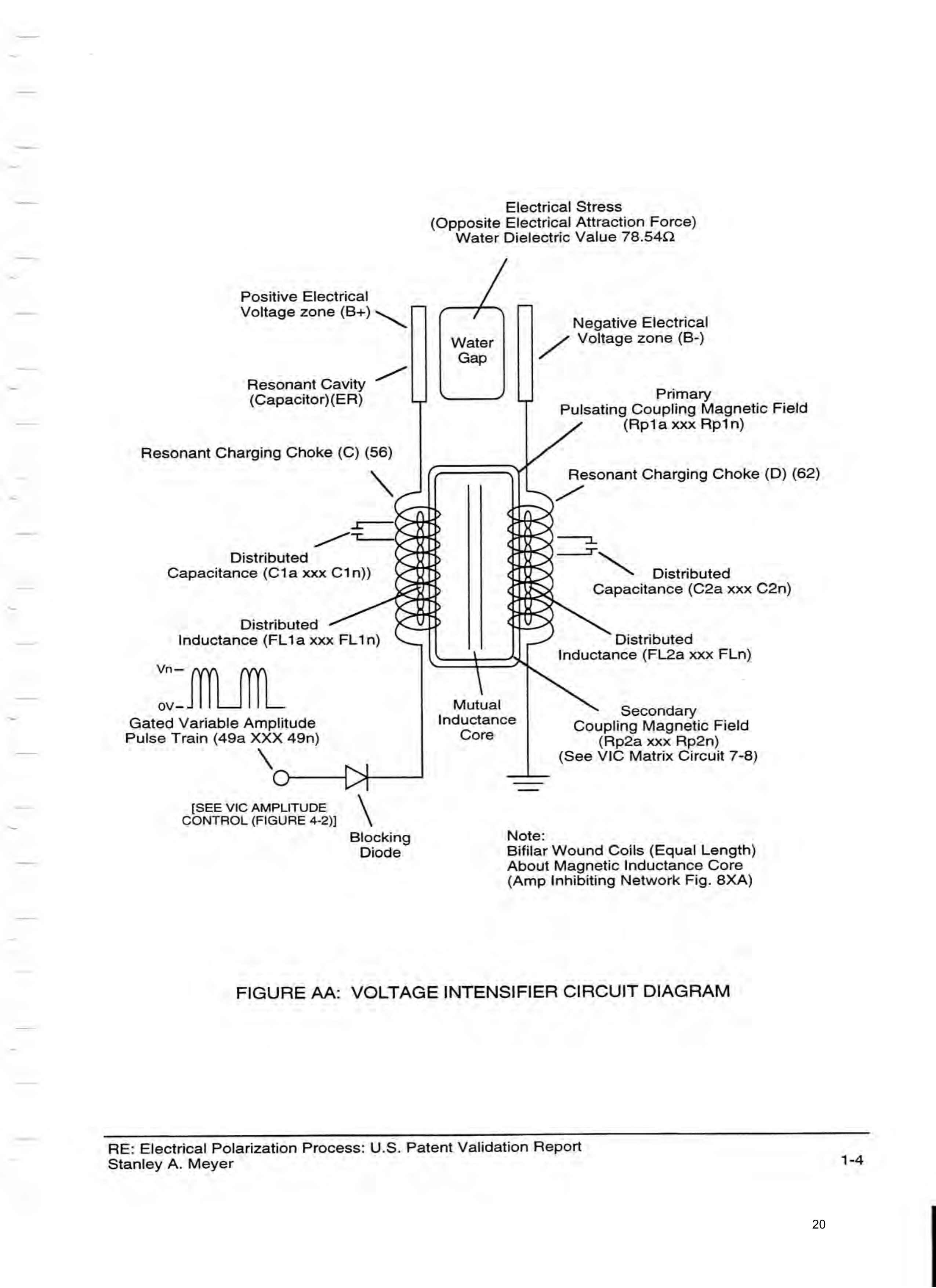
The Amp Inhibiting Circuit (Figure 8XA) is composed of two copper wires “Bifilar” wound (Wrapped) about a magnetic induction core to allow amp restriction (Minimizing Current Leakage) while encouraging “Voltage Potential” across the water molecule to perform WFC “Electrical Polarization Process”, as so illustrated in Figure (7-1) WFC Memo 426 titled VIC Matrix Circuit. The Hi Pulse-Voltage energized “Resonant Charging Choke (56) of Figure (7-1) as to Figure (8XA) creates an electromagnetic coupling field (Rp1) of Figure (7-8) that crosses over and passes through electrically ground connected Resonant Charging Choke (62), as to Figure (8XA1) ... causing amp flow restriction during each Pulsing-Cycle since electrons exhibit electromagnetic characteristic. The resultant Amp Inhibiting Circuit (Figure 8XA) as to (Figure 8XA 1) further allows amp restriction (minimizing current leakage) to be continued even if applied “Voltage Amplitude” is increased. The length and diameter size of the copper-wire spiral wrapped coils (56/62) of Figure (8XA) being paired together and electrically energized in conjunction with applied Voltage Pulse-Frequency determines how much “Amp Leakage” will occur while “Pulse- Voltage Potential” dissociates and separates the water molecule by way of “Opposite Electrical Attraction Force” into water gases of hydrogen, oxygen, and ambient air gases, as so confirmed by Analytical Research Associates, Inc. testing-report herein attached. Connecting Amp Inhibiting
RE: Electrical Polarization Process: U.S. Patent Validation Report: WFC Memo 420 Stanley A. Meyer 4-4
Page 18
Circuit (8XA) to an external Pulsing “Voltage Source” such as a “Step-Up” transformer, now, forms the “Voltage Intensifier Circuit” (VIC) (Figure 8XA1), as so illustrated in VIC impedance network schematic (Figure 7-1) as to VIC Matrix Circuit (7-8). Other amp restricting circuits are, also, applicable such as applying a variable (0-5) volts unipolar pulse-frequency across the armature field-winding of a de-regulated alternator functioning as a pulse-voltage frequency generator, as so illustrated in Photo Exhibits 11B, 11B1, and 11C. The electronic circuit design interfacing determines the amount of “amp leakage” that may occur during WFC ‘€Electrical Polarization Process”.
The “Mode of Operability” of the WFC “Electrical Polarization Process” as so established herein by way of said WFC Test-Report is/was determined by the “Preset” Conditions as so specified by the U.S. Patent Office (35 USC 101) under preselected testing procedures performed by Robert L. Ward (see Robert L. Ward” affidavit relating to technical characteristics of nonchemical ‘Natural Water Hydrogen Gas Generation System” (hereinafter called Water Fuel Cell): various natural water samples analyzed by spectrophotometer method by R & D Laboratory, 2331 Sullivant Ave., Columbus, Ohio 43204, tel. 1-614-274-6467; Analysis of the released watergases by gas Chromatographic method by Analytical Research Associates, Inc., 3274 Maize Road, Columbus, Ohio 43224, Tel. 1-614-267-0279; Analysis by MC Material Joining Consultant of the ” technical Characteristics” of Stainless Steel (T304) material (chemically inert to the Electrical Polarization Process) forming the voltage-zones (hereinafter called Excitor Plates) when immersed in natural water undergoing the “Electrical Polarization Process” ... as so witnessed by Stanley Graumlich and Charles C. Holbrook “Affidavit of Witnessed” as to how said WFC Patent Validation “Test-Report” had been conducted as per WFC “Record of Filing” with the U.S. Patent Office... demonstrating the dissociation of the water molecule by way of “Voltage Potential” before the U.S. Patent Office Scientific Review-Board of Inquiry (January 11, 1984) as so established by said “Certificate of Registration” of said attached WFC U.S. Patent Validation Test-report , as herein presented.
In terms of “Preset” conditions pertaining to the “electrolysis” process of the prior art, chemical additives (electrolyte) such as Sodium hydroxides or Potassium hydroxides must be added to distilled water (typically, 20% per liquid volume) to attempt to maximize hydrogen gas production, as herein the added electrolyte creates a “Dead Short” condition not allowing “Voltage Potential” to exceed two (2) volts potential while linear amp flow proportionally determines hydrogen gas production (see comparison graph titled WFC “‘Mode of Operability” as herein attached), as herein said electrolysis process decomposes both the bi-metals electrodes and the added “electrolyte” simultaneously during said hydrogen gas production, as herein said
RE: Electrical Polarization Process: U.S. Patent Validation Report: WFC Memo 420 Stanley A. Meyer 1-2
Page 19
electrolysis gas-yield nets about one (1) cubic centimeter(CC) per one (1) amp/hr. @ 2 Volts potential... wherein, said electrolysis process solely relying on the use of very high amp flow ... consuming electrical power in the form of heat energy. Contaminates in distilled water and/or said chemically additive (electrolyte) causes “Electrode Filing” (forming a oxidizing coating) which terminates the “electrolysis” prematurely.
Whereas, WFC Electrical Polarization Process (EPP) overcomes the self-destructing effect (Operational Parameters)(Preset Conditions) associated with the prior art “electrolysis” process, while, hydrogen gas-yield related to the “Electrical Polarization Process” far exceeds the prior art “electrolysis” process (see WFC Differential Efficiency Factor) ..._ utilizing chemically inert Stainless Steel (T304) material (decomposition rate .0001/yr) forming opposite “Voltage Zones” (E1/E2)(MC Material Joining Consultant Report) being immersed in natural water (R & D Laboratory Report) ... releasing only hydrogen, oxygen, and ambient air gases from said natural water, as so illustrated in gas-sample report by Analytical Research Associates.
Beyond amp restricting characteristic of said Amp Inhibiting Circuit, the spiral-wrapped coils being paired together (See Figure 8XA, once again), also , causes voltage level enhancement beyond applied voltage input since the “Distributed Capacitance” (Cla xxx Cln = C2a xxx C2n)/ “Distributed Inductance” (FL1a xxx FL1n = FL2a xxx FL2n) of said “bifilar” wrapped coils (Figure 7-3) as to VIC Diagram (AA) encourages the compounding effect (increasing magnetic field-strength during each pulsing cycle) of electromagnetic field-strength (Rpla xxx Rpin = Rp2a xxx Rp2n) (mutual induction) when applied Pulse-voltage Frequency (49a xxx 49n) of Figure (3- 34) passes through the positive energized Resonant Charging Choke (56). Furthermore, the paired coils-wires opposite voltage potentials [positive electrical attraction force (B+) = negative electrical attraction force (B-)] [hereinafter called Electrical Stress (SS’ = RR’) as to (160) of Figure (3-26)] are always equal in electrical magnitude/intensity since the wire-length of each coil are the same. Pulse-voltage repetition rate sets up the step-up electrical charging effect (Figure 1-3) since the “Resonant Cavity” functions as a “Capacitor” (ER) due to the dielectric value of water which becomes an integral part of the VIC Circuit, as so illustrated in (650) of Figure (7-4). The resultant voltage enhancement (Voltage Amplitude) can exceed 40 kilovolts to instantly convert water (droplets) into thermal explosive energy (gtnt), as so illustrated in Voltage Intensifier Circuit Diagram (AA).
RE: Electrical Polarization Process: U.S. Patent Validation Report: WFC Memo 420 Stanley A. Meyer 13
Page 20
Electrical Stress
(Opposite Electrical Attraction Force) Water Dielectric Value 78.542
Positive Electrical
Voltage zone (B+) ~
Negative Electrical
Water Voltage zone (B-)
Gap Pol
Resonant Cavity sane
Capacitor)(ER rim as ire Pulsating Coupling Magnetic Field
(Rpia xxx Rptn)
Resonant Charging Choke (C) (56) Resonant Charging Choke (D) (62)
— Lao
Distributed
Capacitance (C2a xxx C2n)
Distributed
Capacitance (C1a xxx C1n))
Loe Le he he hehe he yan) Oe YY YY
Distributed
Inductance (FL1a xxx FL1n)
Distributed
Inductance (FL2a xxx FLn)
MLM. Ps ov- Mutual Secondary
Gated Variable Amplitude Inductance ling Magnetic Fiel Pulse Train (49a XXX 49n) Core aay nd oe Fiogn) sae (See VIC Matrix Circuit 7-8)
O N cif
[SEE VIC AMPLITUDE \
CONTROL (FIGURE 4-2)]
Blocking Note:
Diode Bifilar Wound Coils (Equal Length)
About Magnetic Inductance Core (Amp Inhibiting Network Fig. 8XA)
FIGURE AA: VOLTAGE INTENSIFIER CIRCUIT DIAGRAM
RE: Electrical Polarization Process: U.S. Patent Validation Report Stanley A. Meyer 1-4
Provenance
- Pages
- pages 16–20 of 140
- Binder
- WFC Project Binder 423-DA
- Method
- pdftoppm 300dpi + tesseract 5 (eng), orientation-corrected
- Source
- WFC International Independent Test-Evaluation Report (1995), scanned binder