patent · CA1234774A1
Hydrogen Generator System
5 April 1988
Page 1
2 te Consumer and Consommation N Corporate Affairs Canada et Corporations Canada
aa) ca) CANADIAN PATENT a2
(54) Hydrogen Generator System
(72) Meyer, Stanley A.,
No. OF CLAIMS 15
Canada
: DISTRIBUTED BY THE PATENT OFFICE, OTTAWA.
Page 2
ABSTRACT
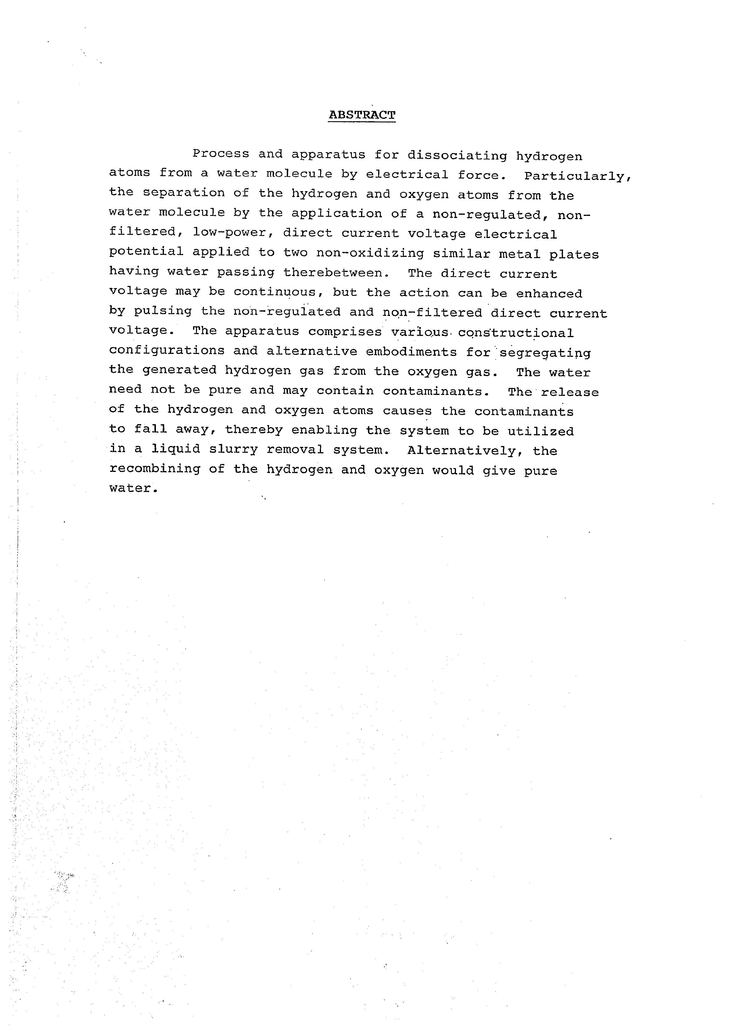
Process and apparatus for dissociating hydrogen atoms from a water molecule by electrical force. Particularly, the separation of the hydrogen and oxygen atoms from the water molecule by the application of a non-regulated, nonfiltered, low-power, direct current voltage electrical potential applied to two non-oxidizing similar metal plates having water passing therebetween. The direct current voltage may be continuous, but the action can be enhanced by pulsing the non-regulated and non-filtered direct current voltage. The apparatus comprises various. constructional configurations and alternative embodiments for ‘segregating the generated hydrogen gas from the oxygen gas. The water need not be pure and may contain contaminants. The release of the hydrogen and oxygen atoms causes the contaminants to fall away, thereby enabling the system to be utilized in a liquid slurry removal system. Alternatively, the recombining of the hydrogen and oxygen would give pure water. .
Page 3
Background 1234774
The potential availability of hydrogen as a Supplement to and eventually complete replacement of the present day available fuels is most appreciated. The efficiency of hydrogen as a fuel and its pollution free qualities further enhances its attractiveness.
The prior art systems have been Successful in splitting the LOS s hydrogen atoms from the oxygen. However, cests per Btu is most
. . . ' NN OK ECESCS
prohibitive and completely restricts the known p: from
commercialization.
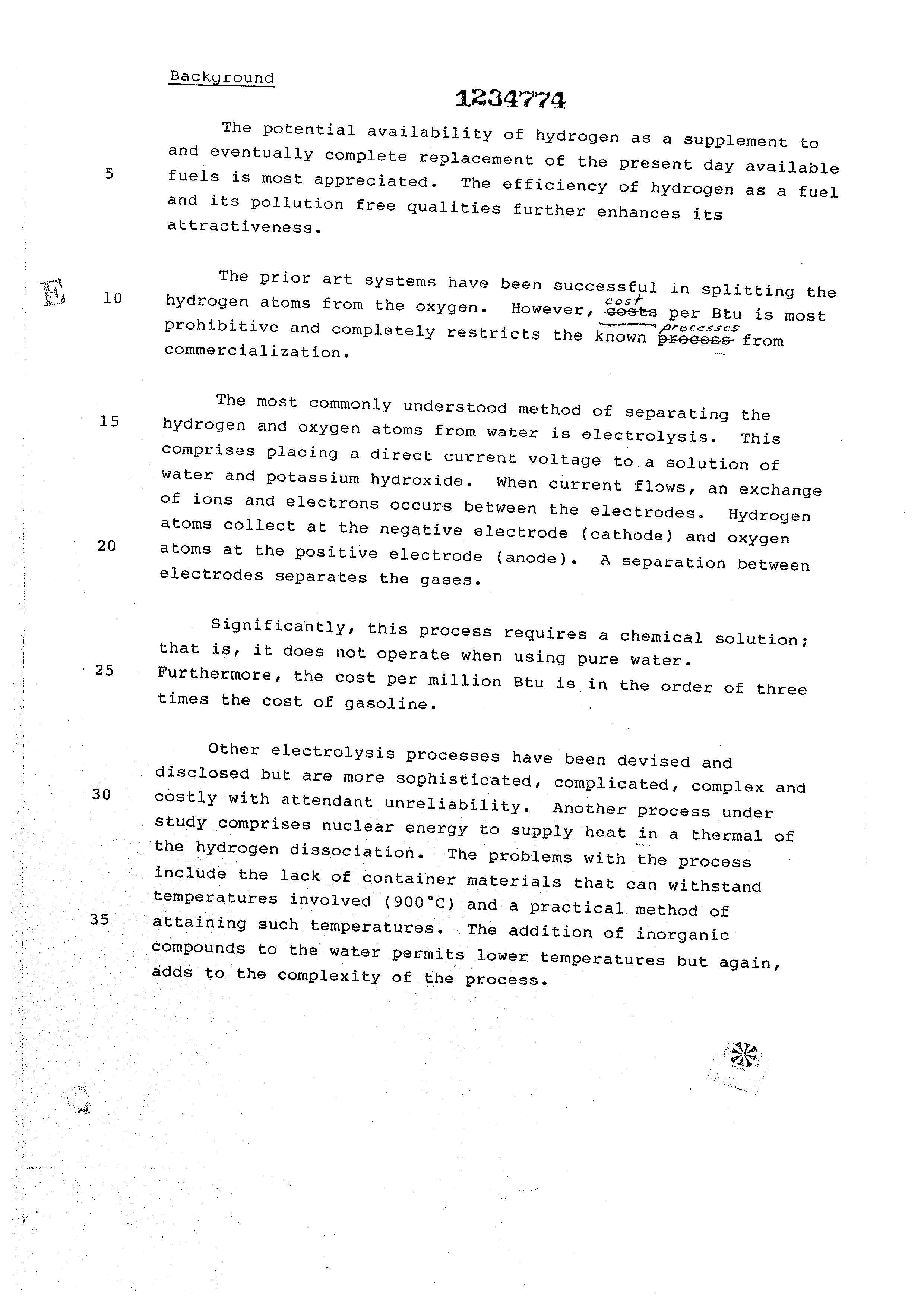
The most commonly understood method of separating the hydrogen and oxygen atoms from water is electrolysis. This comprises placing a direct current voltage to.a solution of water and potassium hydroxide. When current flows, an exchange of ions and electrons occurs between the electrodes. Hydrogen atoms collect at the negative electrode (cathode) and oxygen atoms at the positive electrode (anode). A Separation between electrodes separates the gases.
Significantly, this process requires a chemical solution; that is, it does not Operate when using pure water. Furthermore, the cost per million Btu is in the order of three times the cost of gasoline.
Other electrolysis processes have been devised and disclosed but are more sophisticated, complicated, complex and costly with attendant unreliability. Another Process under Study. comprises nuclear energy to supply heat in 4 thermal of the hydrogen dissociation. The problems with the process include the lack of container materials that can withstand
. temperatures involved (900°C) anda practical method of
attaining such temperatures. The addition of inorganic compounds to the water permits lower temperatures but again, adds to the complexity of the process.
Page 4
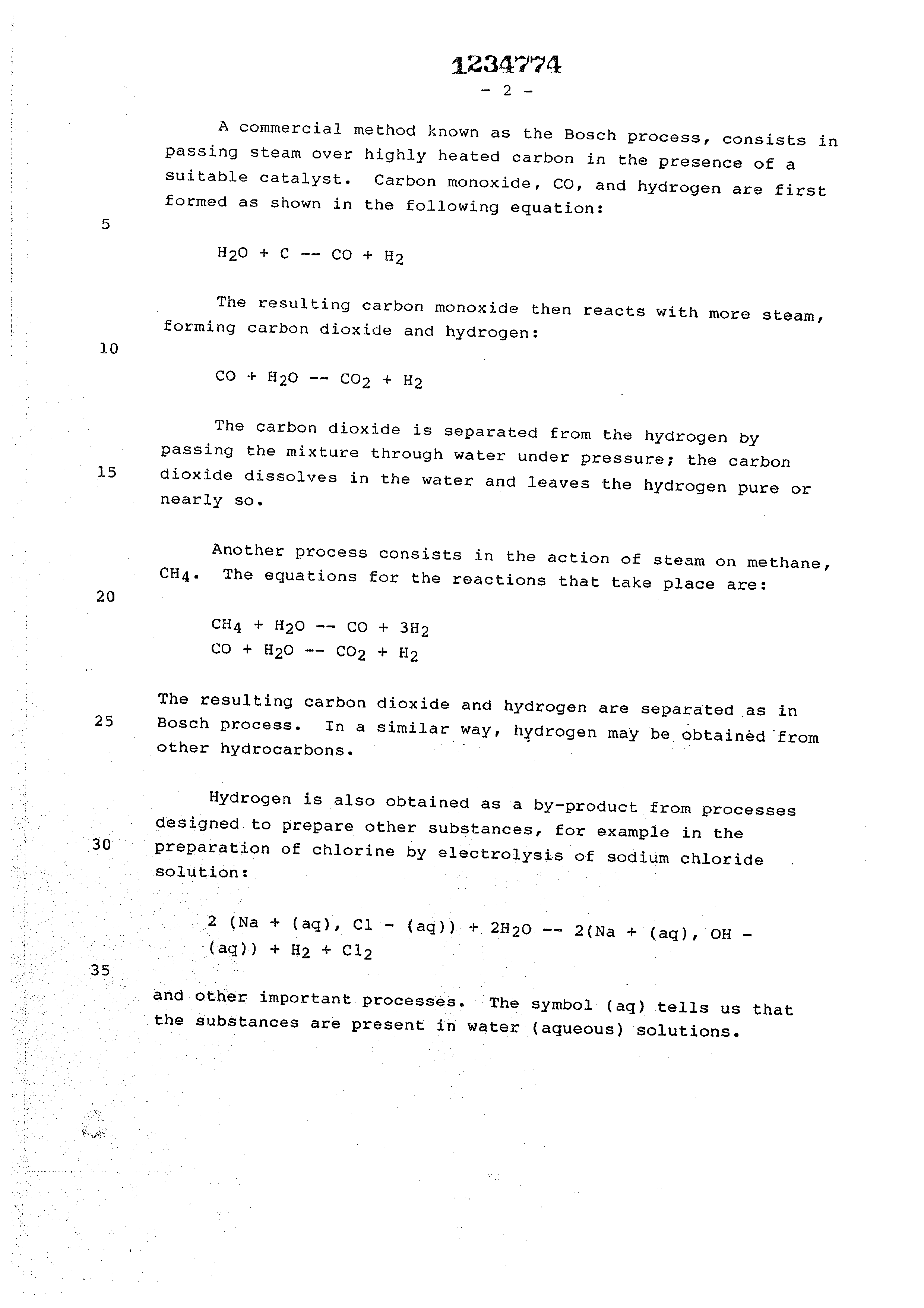
A commercial method known as the Bosch process, consists in passing steam over highly heated carbon in the presence of a Suitable catalyst. Carbon monoxide, CO, and hydrogen are first formed as shown in the following equation:
The resulting carbon monoxide then reacts with more steam, forming carbon dioxide and hydrogen:
The carbon dioxide is Separated from the hydrogen by passing the mixture through water under pressure; the carbon
dioxide dissolves in the water and leaves the hydrogen pure or nearly so.
Another process consists in the action of steam on methane, CHa. The equations for the reactions that take place are:
The resulting carbon dioxide and hydrogen are separated as in
Bosch process. In a similar way, hydrogen may be obtainéd ‘from other hydrocarbons.
Hydrogen is also obtained as a by-product from processes designed to Prepare other substances, for example in the
preparation of chlorine by electrolysis of sodium chloride solution:
and other important processes. The symbol (aq) tells us that the substances are present in water (aqueous) solutions.
Page 5
Finally, there is the natural way of attaining hydrogen by photosynthesis. At best the process is still in the laboratory small-scale stage and those in the art acknowledge the process can produce hydrogen with an
5 efficiency of only 373%.
It is generally acknowledged by scientists that every form of hydrogen production must be explored -~- even if it is too costly, inefficient, or impractical. But,
10 more significantly, hydrogen will be the fuel of the future.
The only question remains how and when it will be produced. Reference is made to the publication Cheaper
Hydrogen. Popular Science, September 1981, pages 10 through
15 14, that reviews and updates the above-noted processes.
Summary of Invention
The process of the present invention, unlike those of the prior art, is a simple, efficient, and low 20 cost process for separating the hydrogen and oxygen atoms from water. No chemicals are added to the water and the
electrical power utilized is only negligible.
In its most fundamental concept the water (which 25 may be uncontaminated or pure water, salt water, or contaminated water) is passed between two plates of similar nonoxidizing metal. The one plate has placed thereon a positive potential and the other a negative potential from a very low direct current voltage power source. The hydrogen
30° atoms are separated and collected for utilization.
The contaminants in the water are dissociated and the dissociated parts may be collected and disposed of or utilized. This in turn leads to recombining the
35° hydrogen and oxygen to form pure water.
The direct current voltage is non-regulated and non-filtered. Experimentation demonstrated that the direct
current voltage acts as a static force on the water molecules;
Page 6
whereas the rippling direct current voltage acts as a dynamic ; ; ¥CEAGS ivy force. Pulsating the direct current further taets—asy a dynamic
force and enhances considerably the splitting of the atoms from the water molecules.
The apparatus for carrying out the process is extremely Simple and can be manufactured most inexpensively. Certain plate arrangements and configurations are disclosed with graphical illustration of relative efficiency. Alternative 10 structure for separating and collecting the hydrogen from the oxygen is disclosed.
Objects
15 It is accordingly a principal object of the present invention to provide method and means that is operable for producing hydrogen and oxygen from any natural water irrespective of its purity.
; 20 Another object of the present invention is to provide a hydrogen/oxygen generator that is operable from very low
electrical power, extremely efficient, and wherein the cost of operation is minimal.
25 Another object of the present invention is to provide a, . hydrogen/oxygen generator using water containing contaminants,
and thereafter recombining the hydrogen/oxygen to form pure water.
30... Still another object of the present invention is to provide a hydrogen/oxygen generator that utilizes apparatus of simple and low cost materials, and which structure can be made in varying sizes, and duplicated without loss of efficiency.
35 Other objects and features of the present invention will become apparent from a reading of the detailed description of the preferred embodiment and its alternative structures when taken in conjunction with the drawings in which:
Page 7
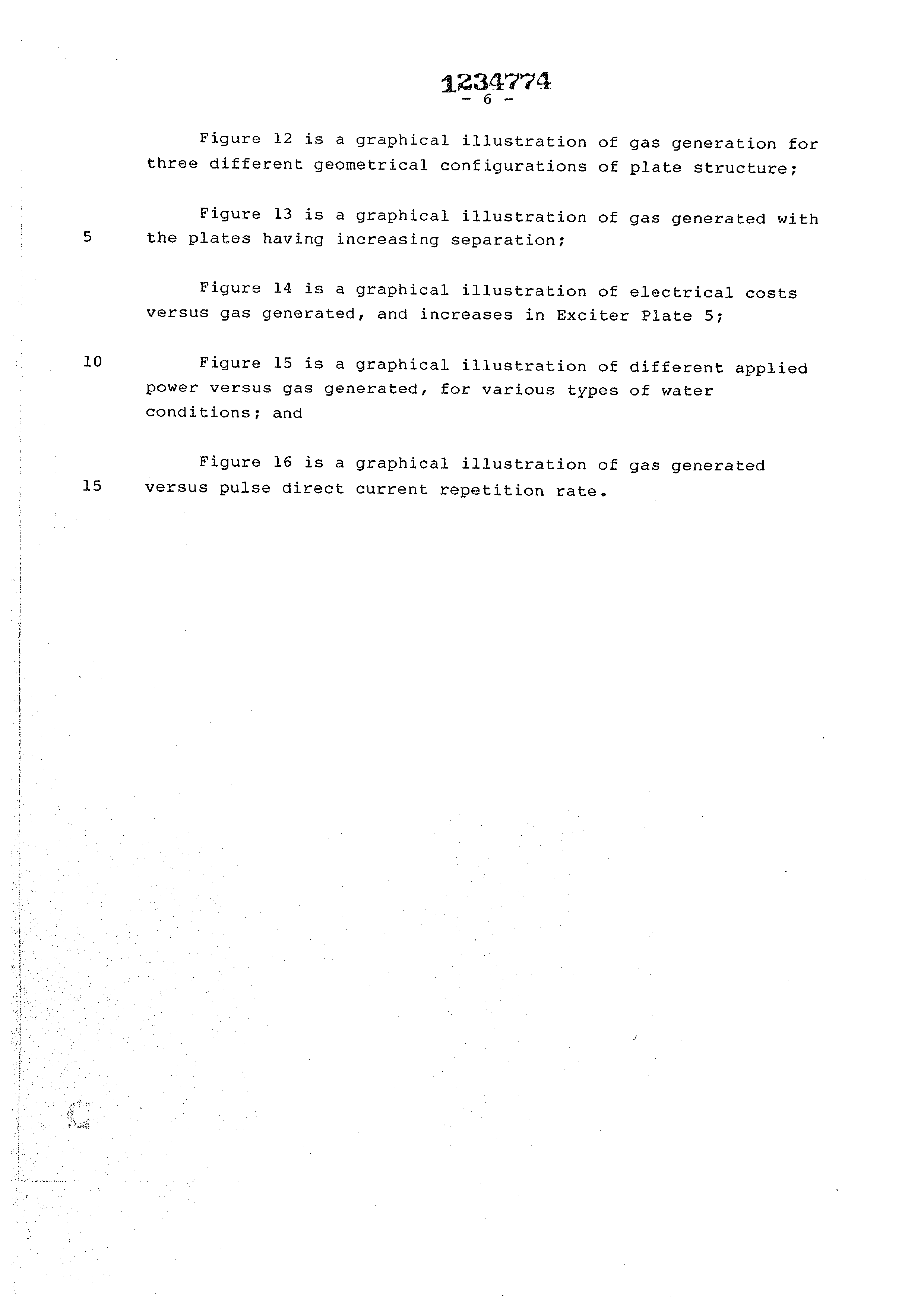
BRIEF DESCRIPTION OF THE DRAWINGS
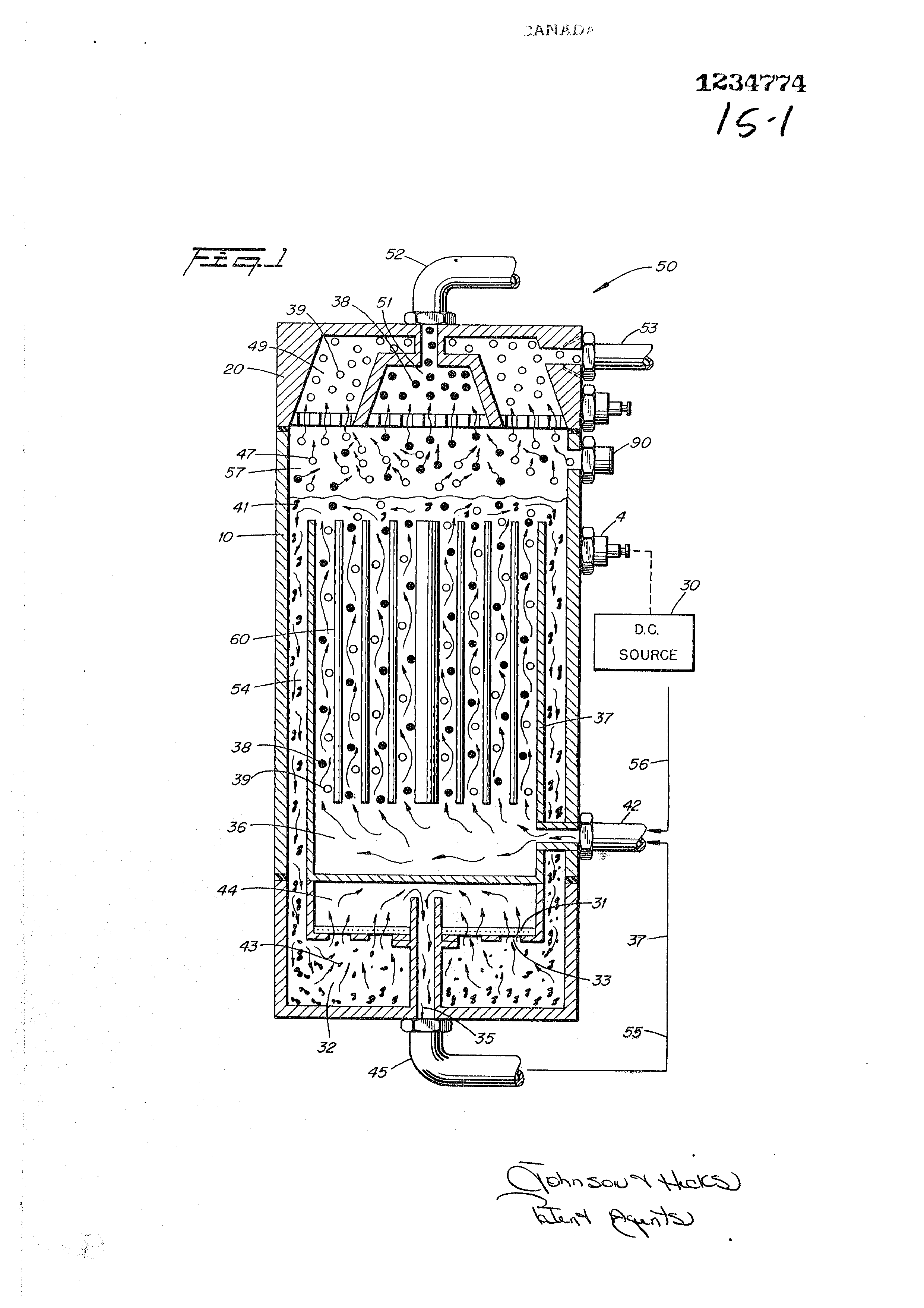
Figure 1 is an illustration in cross~section of the operable constructed preferred embodiment of the present invention;
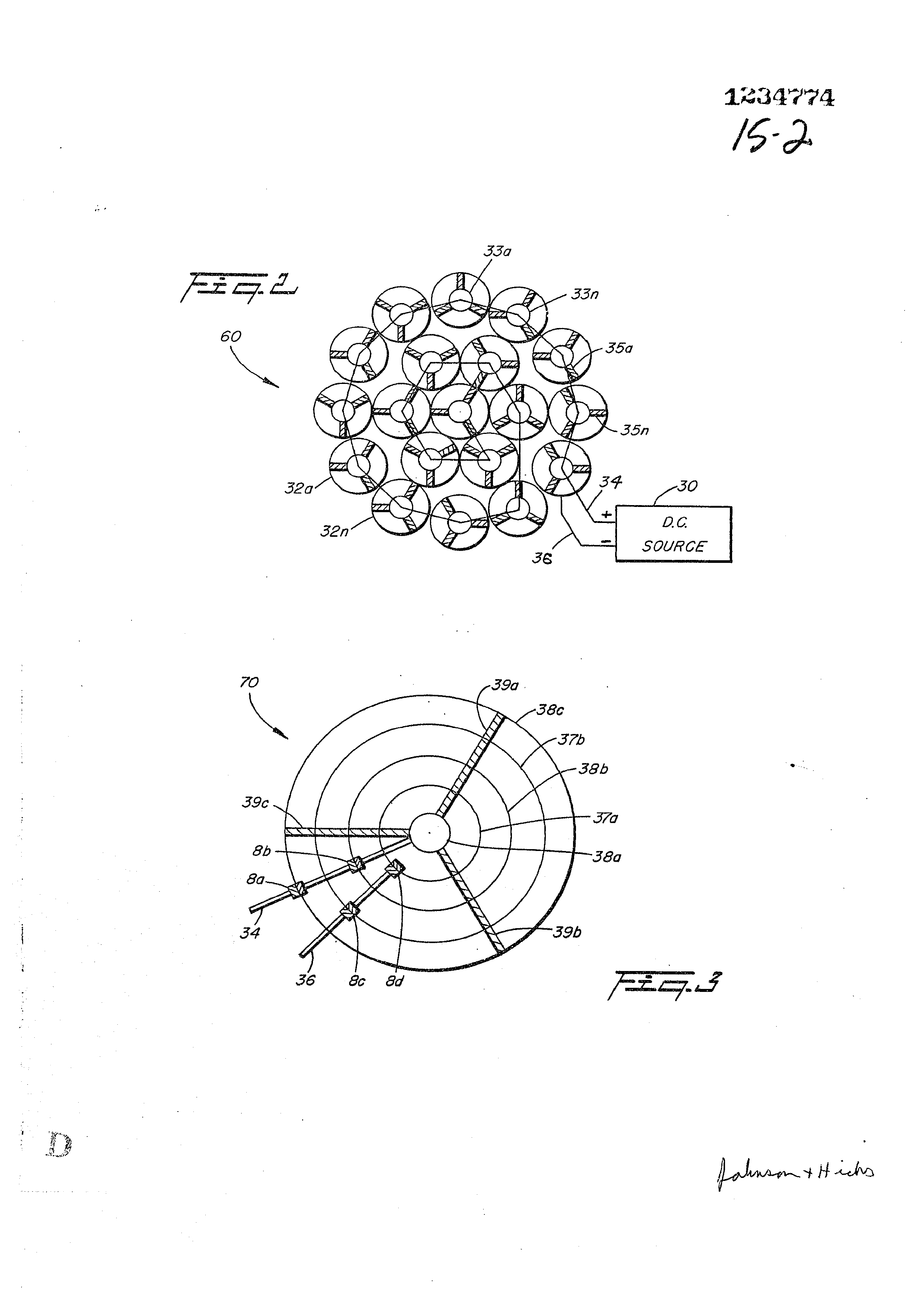
Figure 2 illustrates a coaxial cluster Or array of plates utilized in the embodiment of Figure 1;
Figure 3 is a first alternative plate arrangement, a concentric coaxial array?
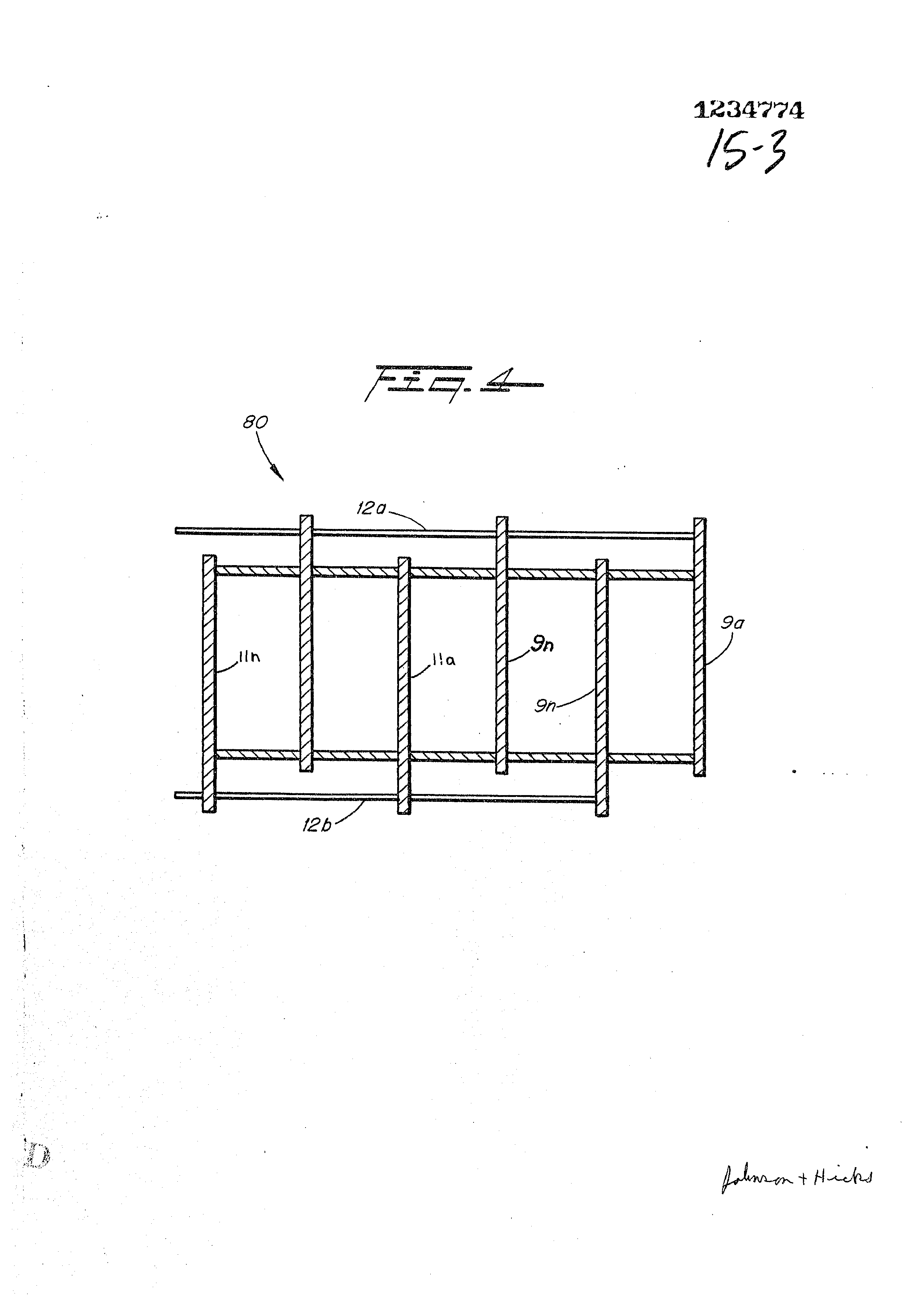
Figure 4 is another alternative plate arrangement, a flat plate array;
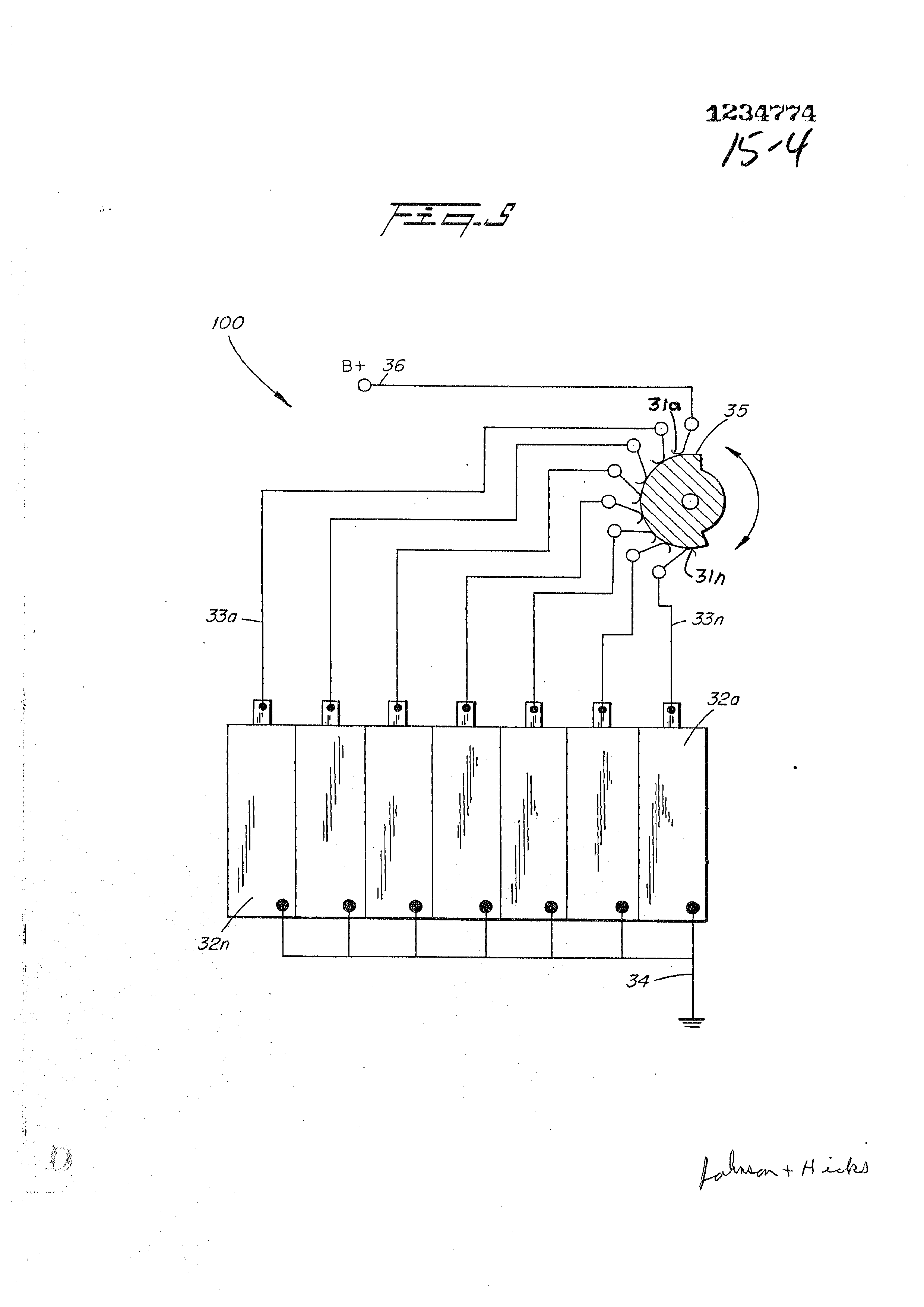
Figure 5 diagramatically illustrates applying a voltage potential to several plates;
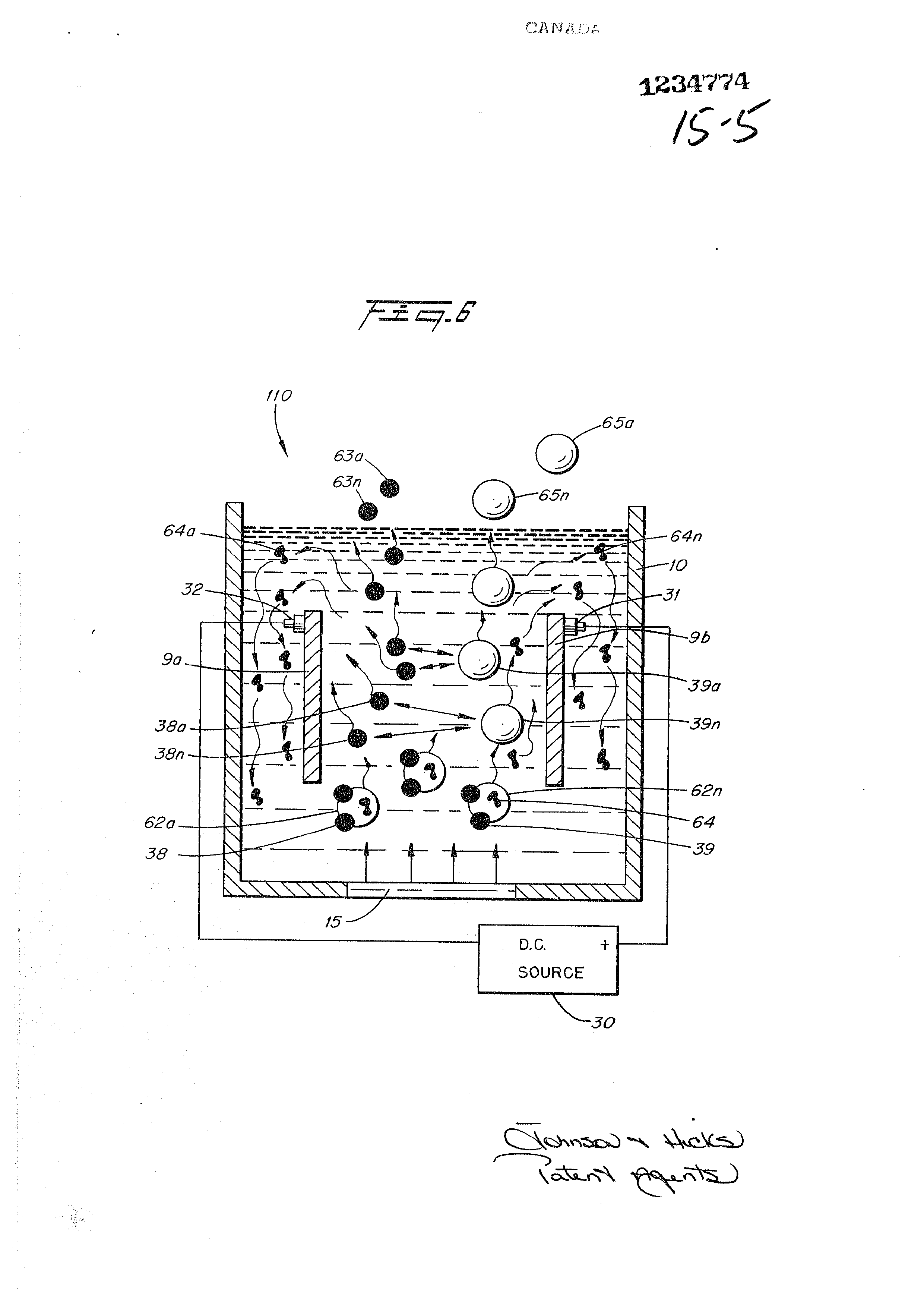
Figure 6 illustrates the principles of the present invention in its most simplified embodiment;
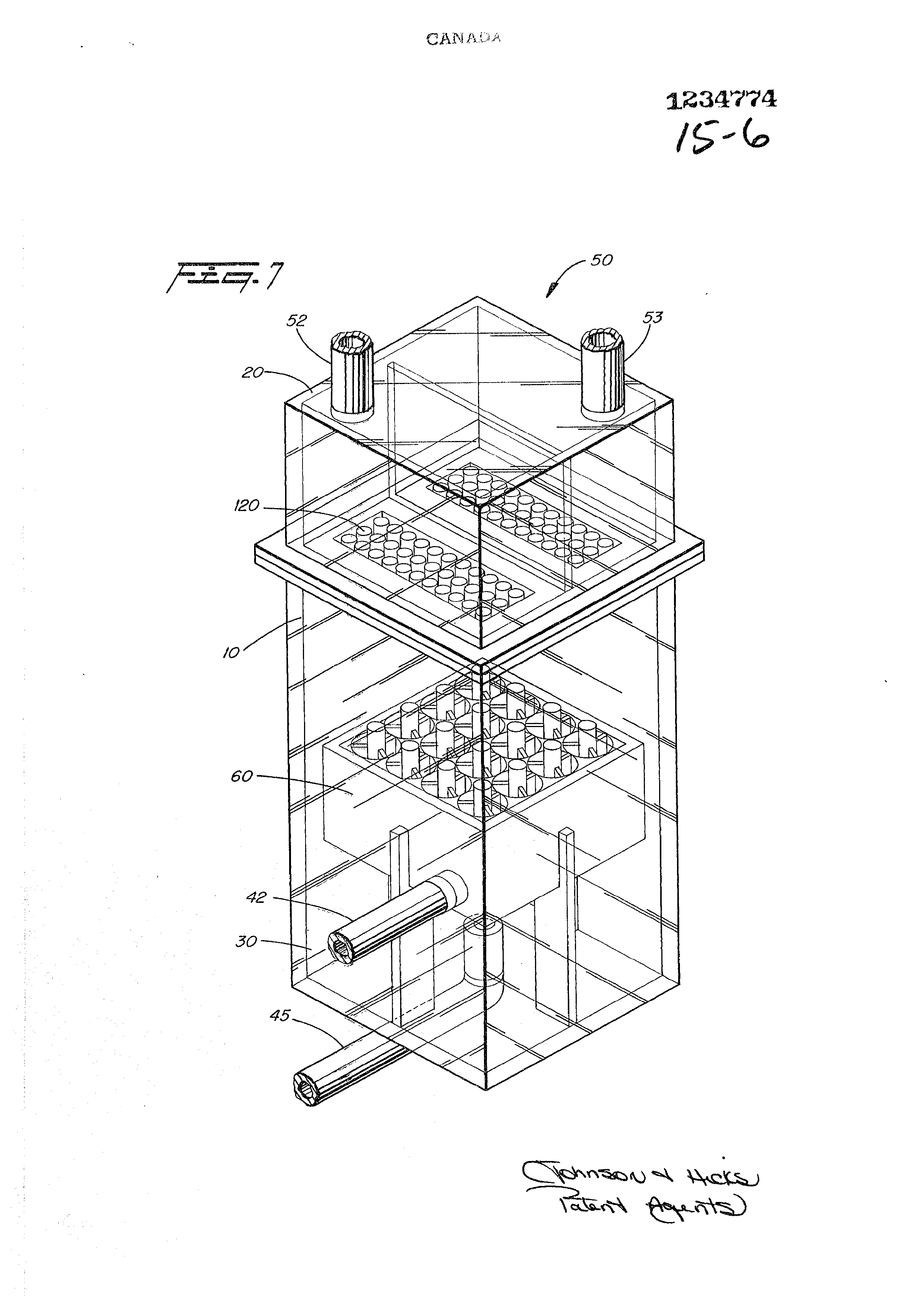
‘Figure 7 is the preferred embodiment shown in Figure 1 except in this illustration, the view is perspective;
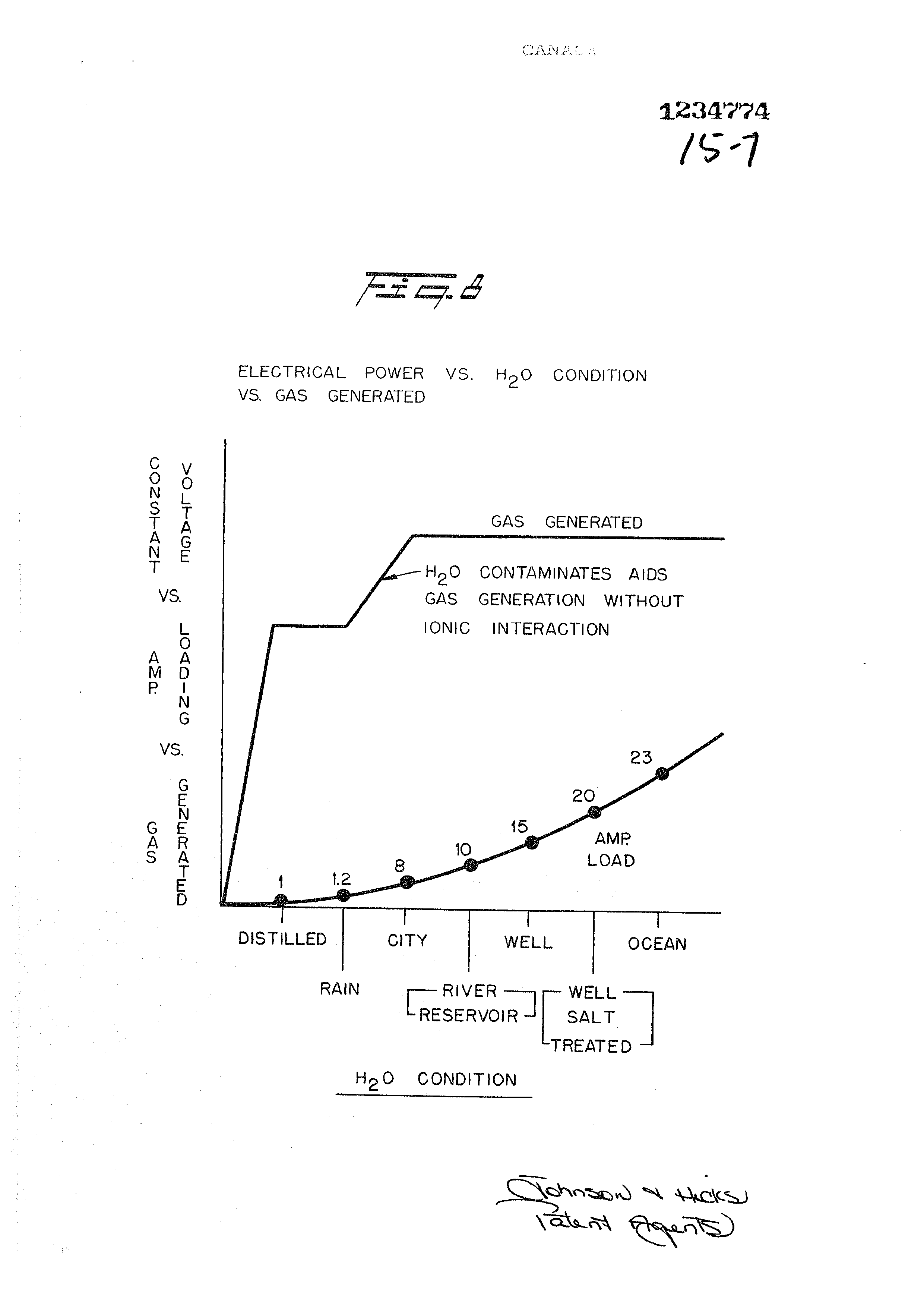
Figure 8 is a graphical illustration of amperage versus gas
generated, and effect as to condition of water;
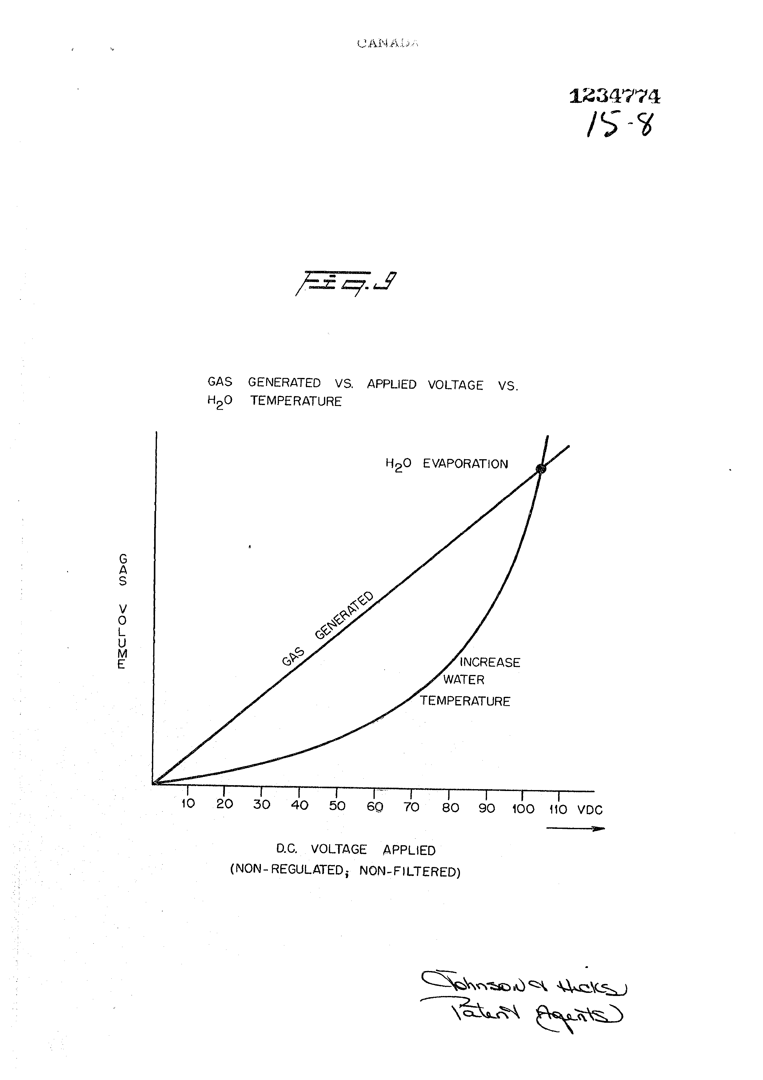
Figure 9 is a graphical illustration of D.C. voltage versus gas generated, and increases in water temperatures;
generation
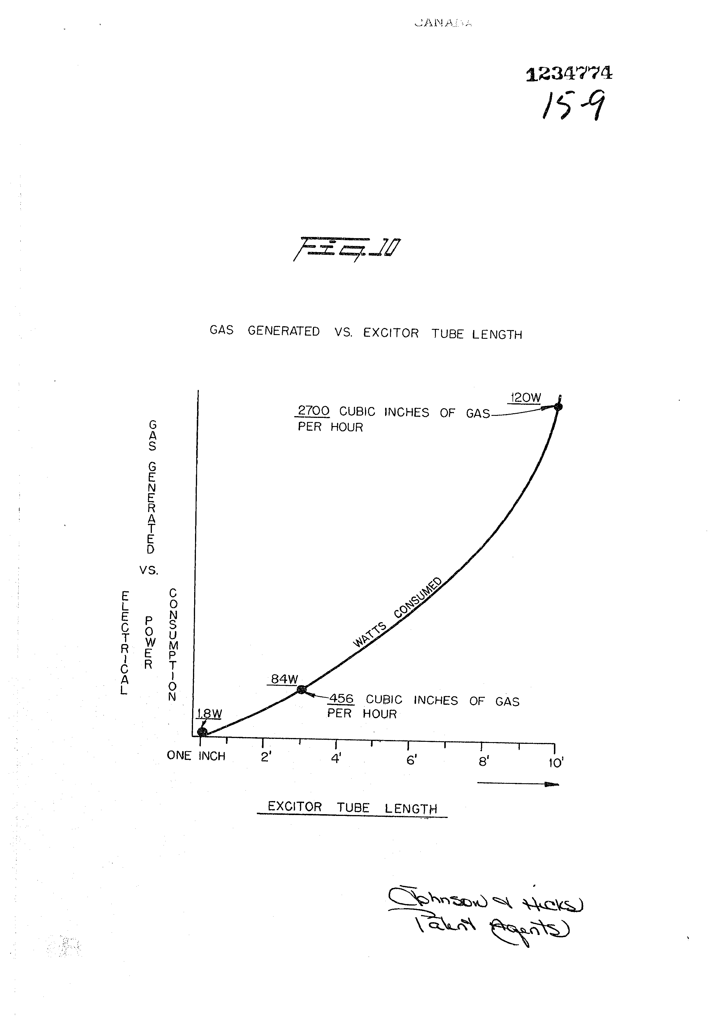
Figure 10 is a graphical illustration of-gas donerator versus tube length in a tubular plate arrangement:
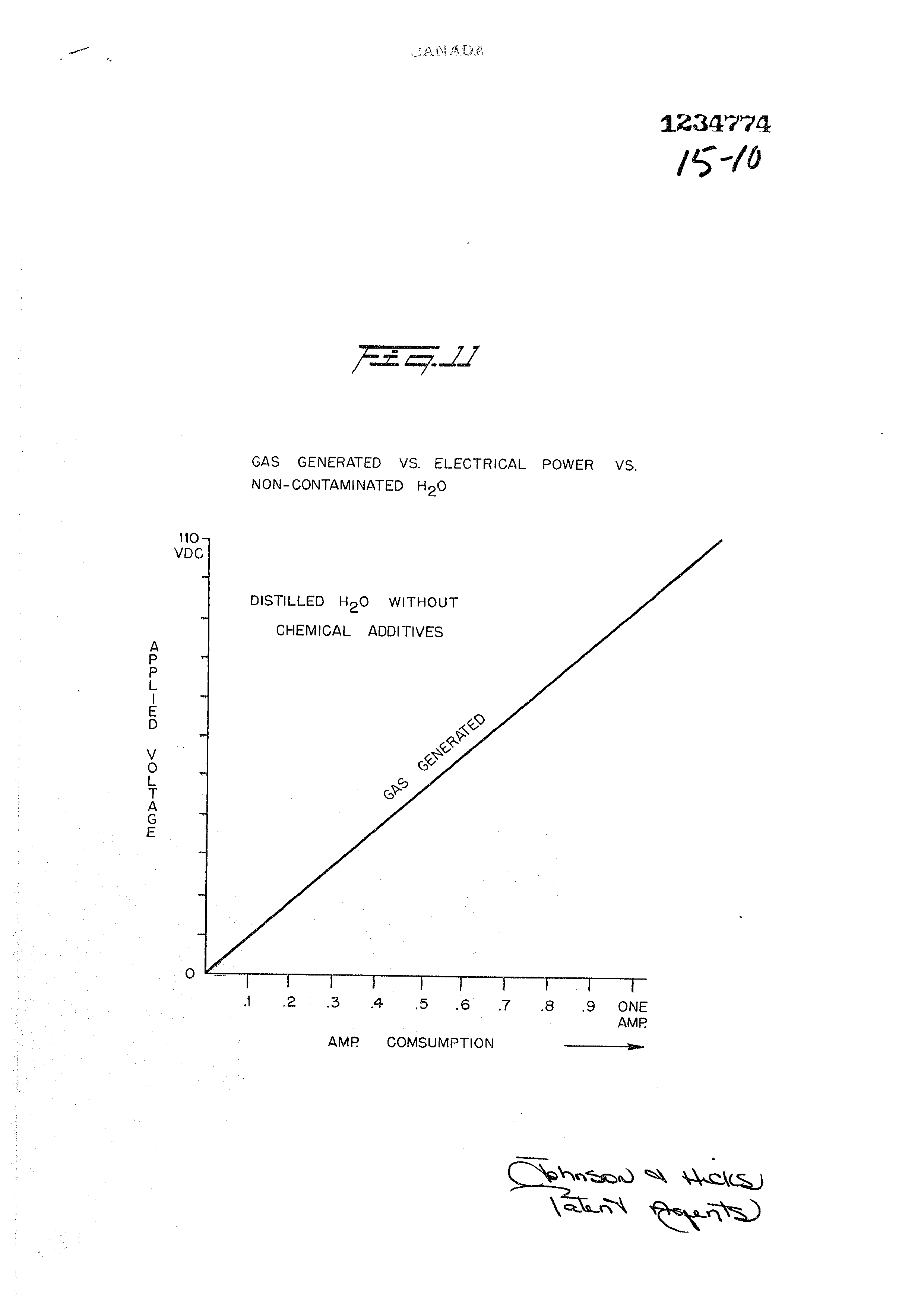
Figure 11 is a graphical illustration of applied power
versus gas generated for pure water;
Page 8
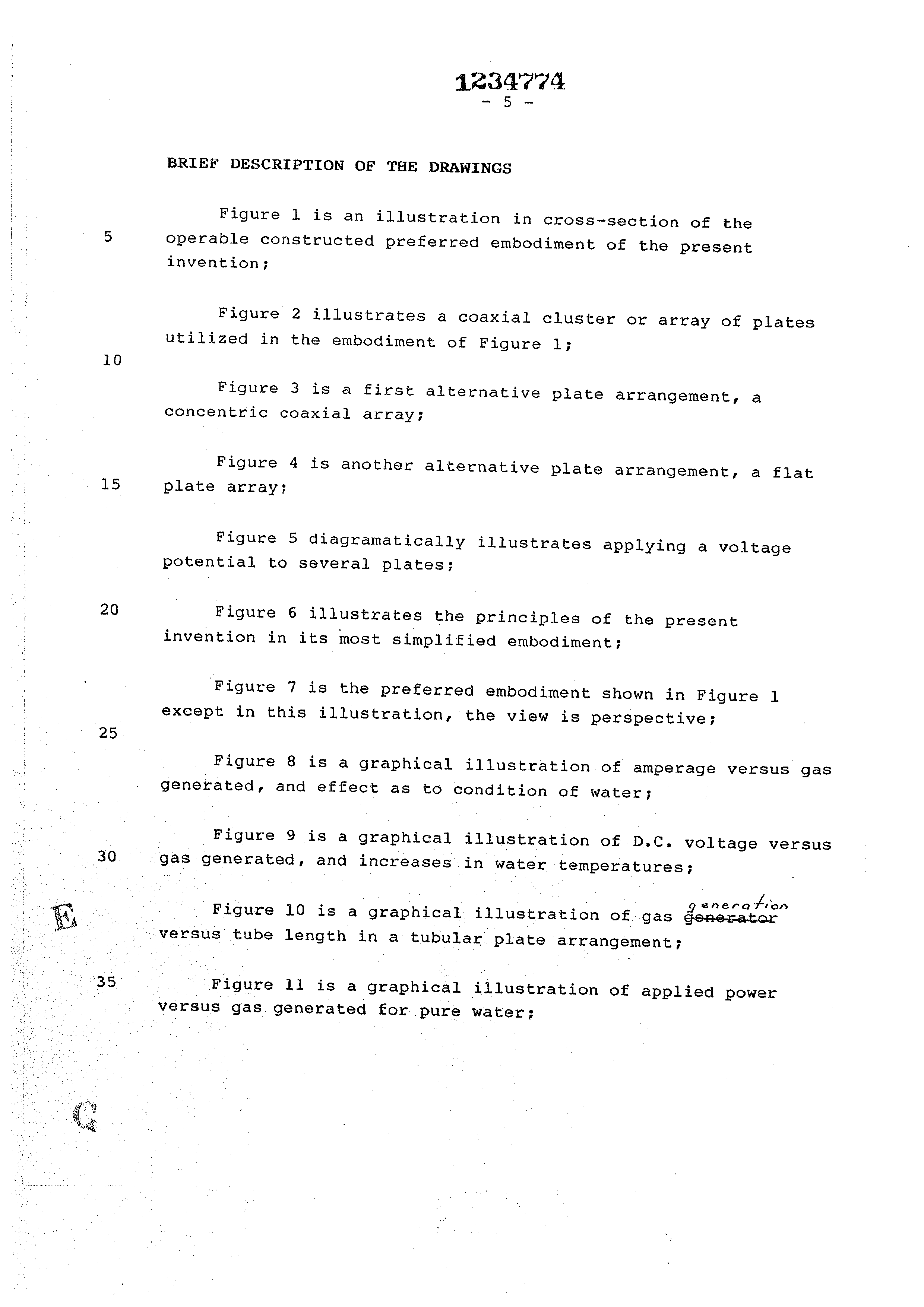
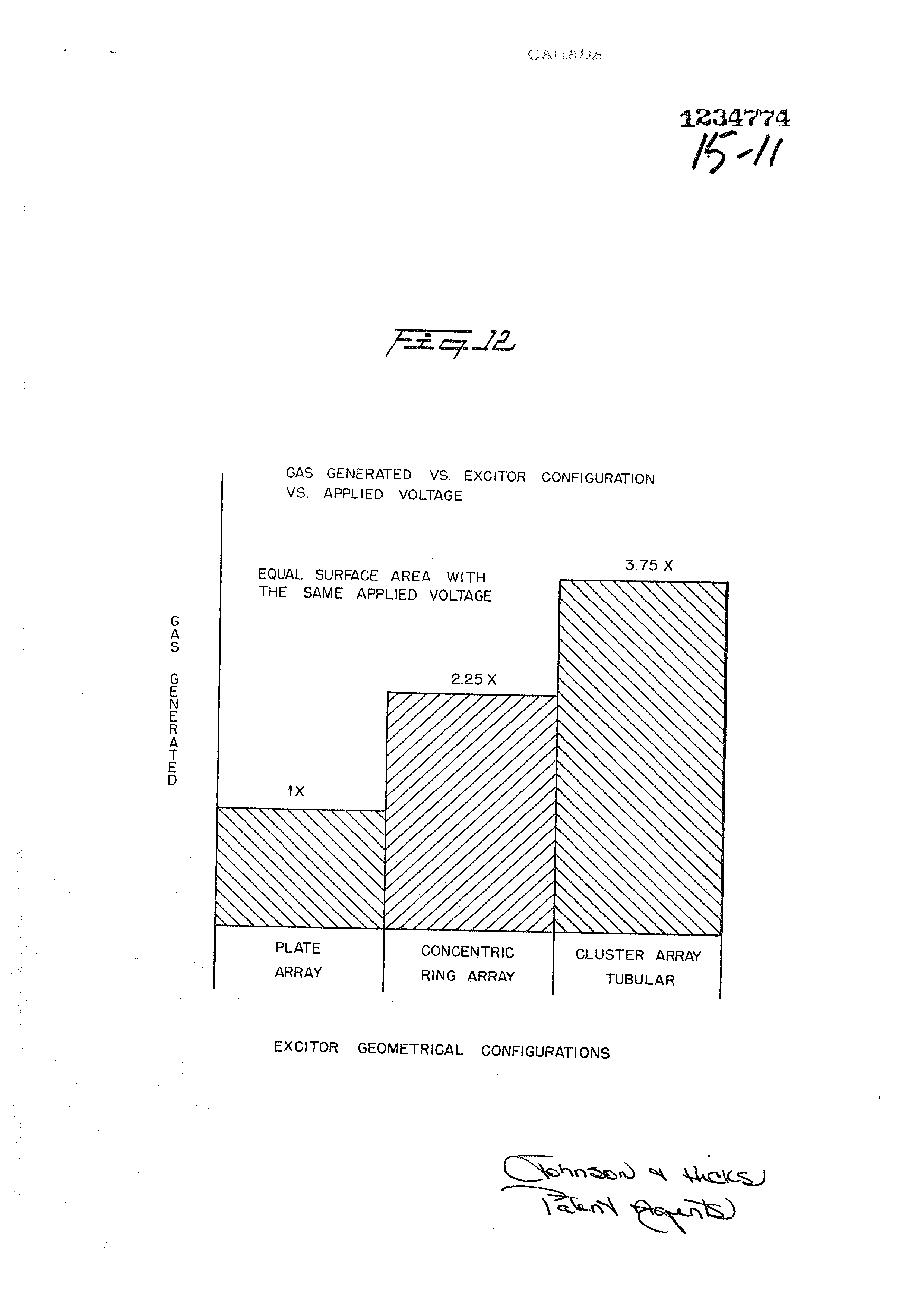
Figure 12 is a graphical illustration of gas generation for three different geometrical configurations of plate structure;
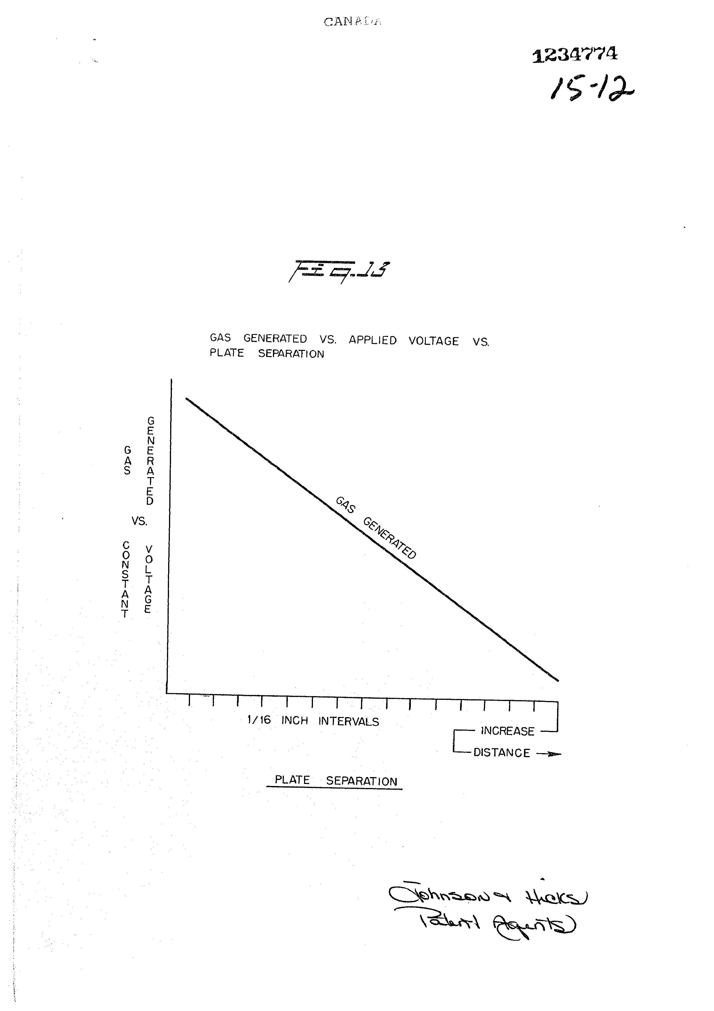
Figure 13 is a graphical illustration of gas generated with the plates having increasing separation;
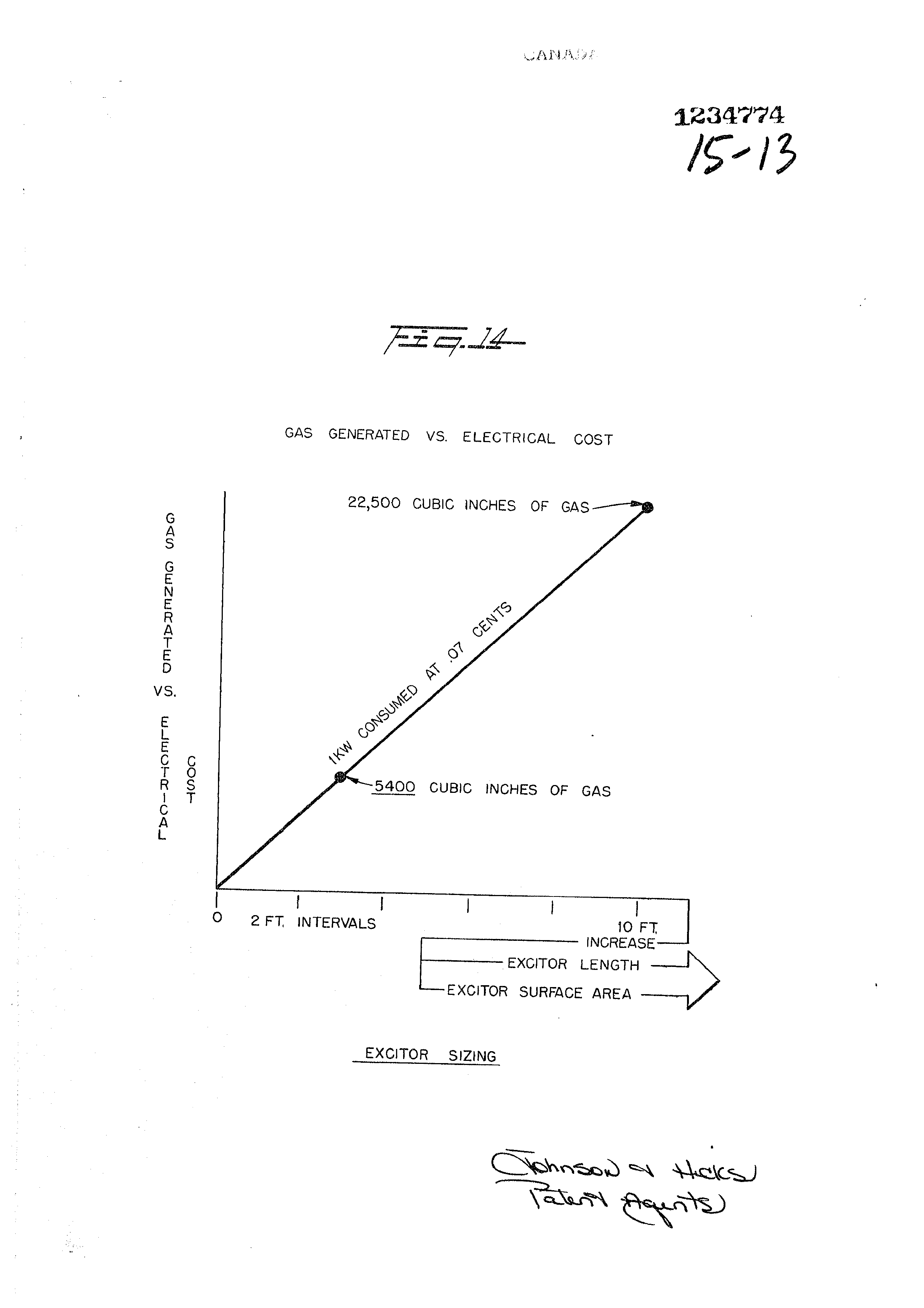
Figure 14 is a graphical illustration of electrical costs versus gas generated, and increases in Exciter Plate 5;
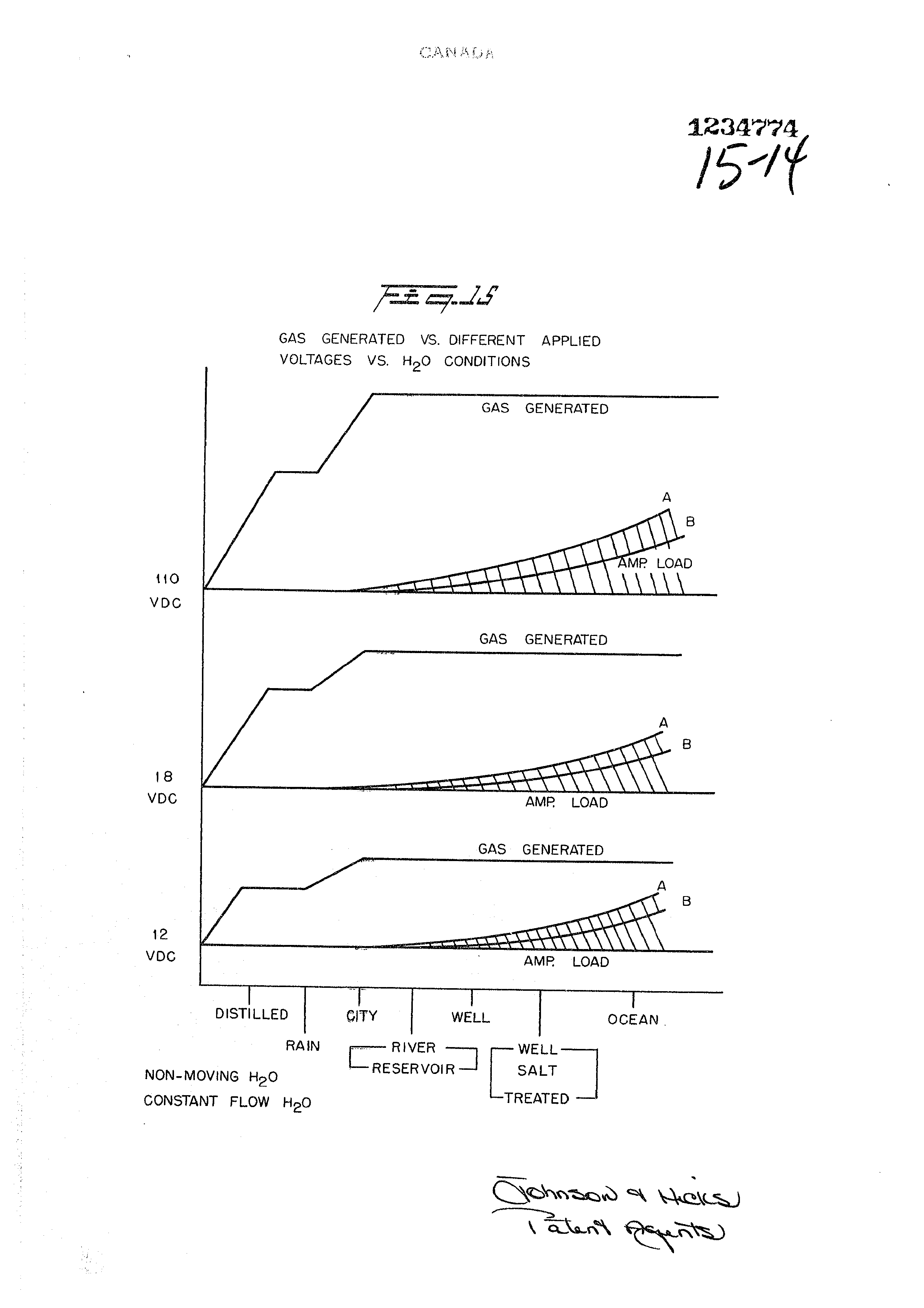
Figure 15 is a graphical illustration of different applied power versus gas generated, for various types of water conditions; and
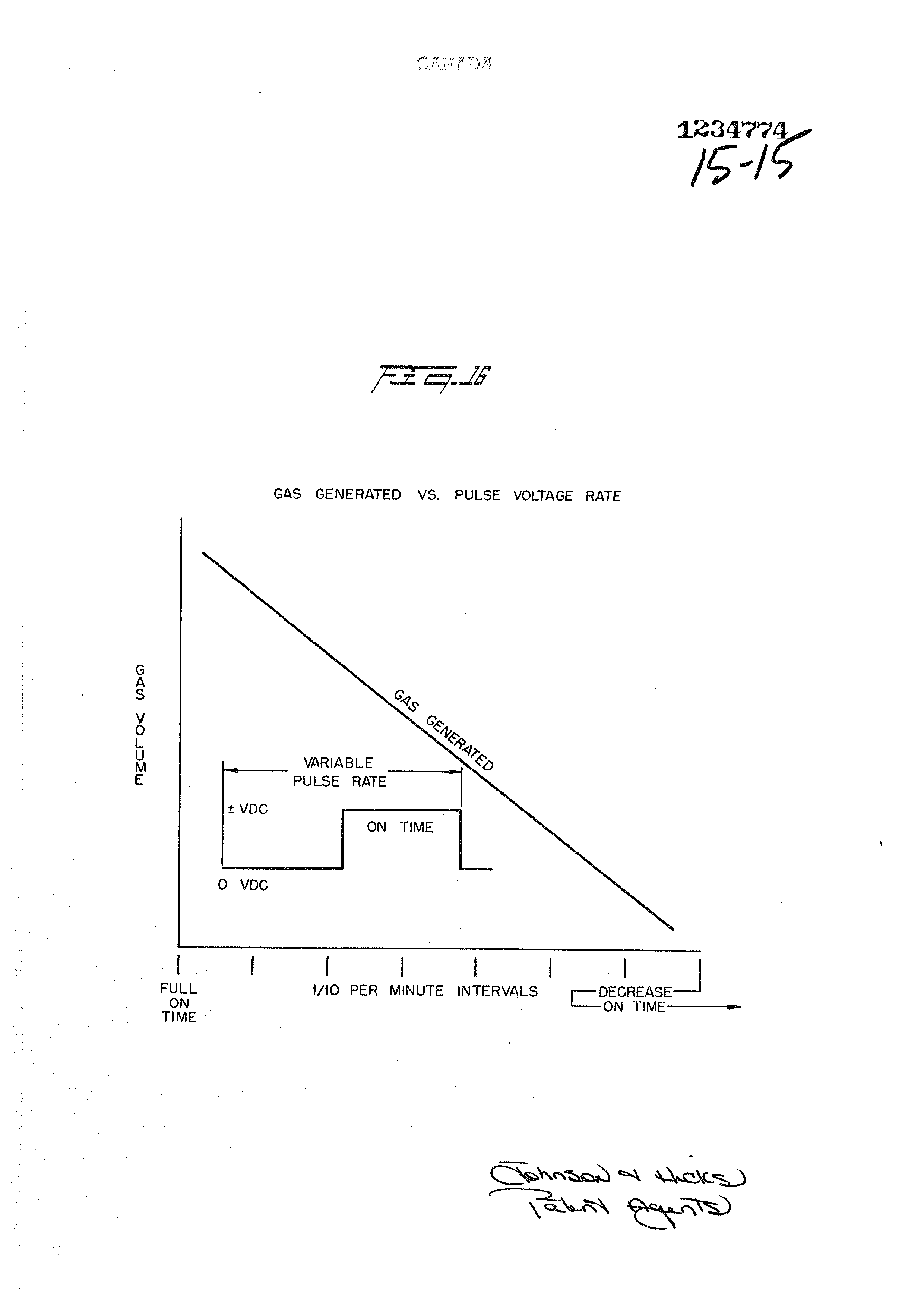
Figure 16 is a graphical illustration of gas generated versus pulse direct current repetition rate.
Page 9
Detailed Description of Invention as Depicted in Drawings
With particular reference now to Figure 6, there is illustrated schematically in cross-section the invention in its most simplified embodiment.
A structure 110 contains water supply 15 comprising molecules 62a xxx 62n, of hydrogen 38a xxx 38n, oxygen, 39a xxx 39n, and foreign substances 64a xxx 64n. A pair of plates 9a and 9b consisting of non-oxidizing metal -- and both of the same metal, are submerged in the water 15.
Attached to terminal 32 on the first of the plates 9a is a wire having its other end connected to the negative terminal power source 30 and another wire is connected to terminal 31 on plate 9b the other end of such wire being connected to the
positive terminal of the aforesaid direct current voltage electrical source 30. ,
The direct current voltage applied to the water passing between plates 9a and 9b is sufficient to dissociate the hydrogen atoms 38a xxx 38n and oxygen atoms 39a xxx 39n (appearing as bubbles) from the water molecules 62a xxx 62n. The forceful action of the applied potential attacks the molecule structure of the water and not its atomic structure. The foreign substance or contaminants 64a xxx 64n are ‘broken’ away from the water molecule 62a xxx 62n, and spill over the Outside area of the plates 9a and 9b to a collector at the bottom of the tank 10.
The hydrogen gas 63a xxx 63n and oxygen gas 65a xxx 65n rises above the liquid. The gases are separated, collected and
thereafter utilized all as set forth below.
The process shown with the apparatus of Figure 6 is operable, as depicted schematically, in its most crude form. To increase and enhance the action, the process and the apparatus
are improved upon as shown in the constructed and preferred
Page 10
Sabu kee sete Dewees
embodiment of Figure 1 (a cross~sectional view) and Figure 7 (a perspective view).
The voltage source 30 (Shown schematically in Figure 5)
5 supplies a direct current voltage that is rectified but not filtered and not regulated. That is, the direct current voltage is rippled and unregulated. The varying amplitude 688K8, ripples, in terms of applied force act as a constant static physical force.
The amount of electrical power required by the hydrogen/oxygen generator of the preferred embodiment, as illustrated, is surprisingly minimal. For the embodiment shown
in Figures 1, 2 and 7, the power source 30 supplies 12 volts at 15 1 ampere.
It can be appreciated, that increasing the voltage would enhance the forceful action upon the water molecule. The corelation of gas generated vs. electrical energy is graphically
20 illustrated in Figure 11. The gas generated is a linear function of the magnitude of voltage applied. However, there is a serious limitation to increasing the voltage. As the voltage/current is increased the temperature of the water increases and eventually reaches a condition where steam is
25 generated -- as illustrated graphically in Figure 9. Further, as shown graphically in Figure 8, the current versus gas generated is also a function of the type of water utilized.
Therefore, in lieu of increasing the electrical power to 30 enhance the action on the water molecules, other conditions must be considered. The first is to alter the plate source direct current voltage waveform,
With particular reference to Figure 5 there is illustrated 35° an electronic switch for switching on and off the rippled D.C. output of supply 30... The tipple is not removed. The plates 32a ¥xx 32n are connected to a common ground 34. The positive terminals 33a xxx 33n are connected respectively to contacts 3ia
heagerey,
Page 11
Xxx 31n of switch 35 rotatively making and breaking contact
with the direct-current voltage source 30.
In function the pulsed rippled output voltage functions to forcefully apply to the water molecules a dynamic force, the pulse repetition rate determining the
amount of gas generated.
Other structured factors affecting the hydrogen gas generation comprise altering (1) plate size, (2) plate spacing, (3) number of plates, and (4) the plate configuration. All of these factors have been taken into consideration in the development of a plate configuration to provide
optimum results for a preferred embodiment.
With reference to Figure 2, there is shown an array or cluster of tubular plates utilized in the preferred embodiment of Figures 1 and 7. The term "plate" hereinafter, is intended to convey a large area electrical surface; and whether the surface is flat, curved, tubular or otherwise, is of no consequence except as hereinafter defined. Particularly, each tubular plate comprises an outside tube 32a XXX 32n, and an inside tube 33a xxx 33n. Connecting each of the inner tubes 33a xxx 33n is a terminal wire 34; and connecting each of the outside tubes through a common ground is a terminal wire 36. The two terminal wires 34 and 36 are connected to the positive and negative side respectively of the direct current voltage source 30. Intermediate the outside and inside tubes are a series of spacers 35a Xxx 35n.. The coaxial tubes in an array are shown pictorially
in the perspective view of Figure.7.
With particular reference to Figure 3 there is illustrated, as an alternative to that utilized in the
preferred. embodiment, another plate arrangement and configura-
tion. . This concentric ring array comprises a series of
co-axial radially spaced tubes with equal spacing between
adjacent tubes. The center tube 38a and the alternate tubes 38b and 38c serve as the positive plates connected
to positive wire terminal
Page 12
34. Each of the tubular plates 38a, 38b, and 38c is interconnected via connectors 8a and 8b to wire terminal 34. The three spacers 39a, 39b, and 39c maintain a uniform spacing
between the respective tubular plates.
With particular reference to Figure 4 there is shown still another plate arrangement and configuration. In this embodiment, shown in cross-section, the positive plates 9a xxx 9n are interconnected by electrode 12a whereas the negative plates lla xxx lln are interconnected by the electrode 12b.
With particular reference to Figure 12 there is illustrated graphically the efficiency of the tubular plate array of Figure 2, the cluster tubular array of Figure 3, and the flat plate array of Figure 4. Specifically there is shown the gas generation versus the plate configuration. It can be appreciated from this graph why the embodiment of Figure 1 includes the cluster tubular array of Figure 2.
As stated above another factor affecting the gas generation output is the plate separation. With particular reference to Figure 13 there is illustrated graphically plate spacing versus gas generation. As can be seen, the greater the Spacing the less gas generation. The efficiency versus spacing of the plates is a linear decrease with spacing.
As stated abvove, the applied direct current voltage across the positive current voltage plates having water therebetween is a force applied -- in the nature of a physical force -- to the water molecules. The applied force is sufficient to cause the hydrogen and oxygen atoms to dissociate themselves from the
water molecule and anything else that may be included therewith.
In the aforementioned prior art system of hydrogen gas generation such as the electrolysis process, it is essential that the water be distilled or otherwise made pure.
Page 13
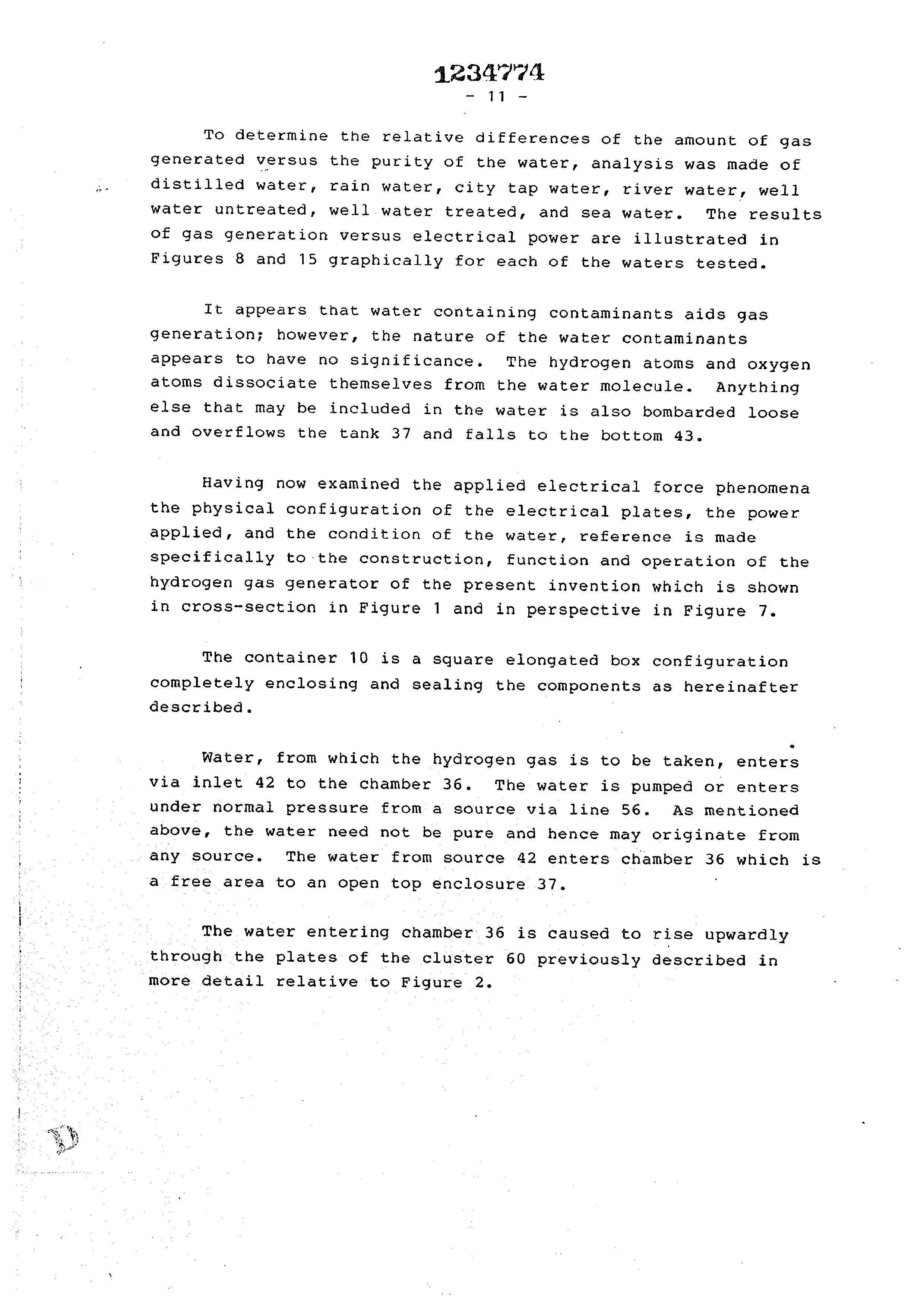
To determine the relative differences of the amount of gas generated versus the purity of the water, analysis was made of Gistilled water, rain water, city tap water, river water, well water untreated, well water treated, and sea water. MThe results of gas generation versus electrical power are illustrated in Figures 8 and 15 graphically for each of the waters tested.
It appears that water containing contaminants aids gas generation; however, the nature of the water contaminants appears to have no significance. The hydrogen atoms and oxygen atoms dissociate themselves from the water molecule. Anything else that may be included in the water is also bombarded loose and overflows the tank 37 and falls to the bottom 43.
Having now examined the applied electrical force phenomena the physical configuration of the electrical plates, the power applied, and the condition of the water, reference is made specifically to-the construction, function and operation of the hydrogen gas generator of the present invention which is shown in cross-section in Figure 1 and in perspective in Figure 7.
The container 10 is a square elongated box configuration
completely enclosing and sealing the components as hereinafter described.
Water, from which the hydrogen gas is to be taken, enters via inlet 42 to the chamber 36. The water is pumped or enters under normal pressure from a source via line 56. As mentioned above, the water need not be pure and hence May originate from any source. The water from source 42 enters chamber 36 which is a free area to an open top enclosure 37.
The water entering chamber 36 is caused to rise upwardly
through the plates of the cluster 60 previously described in more detail relative to Figure 2.
Page 14
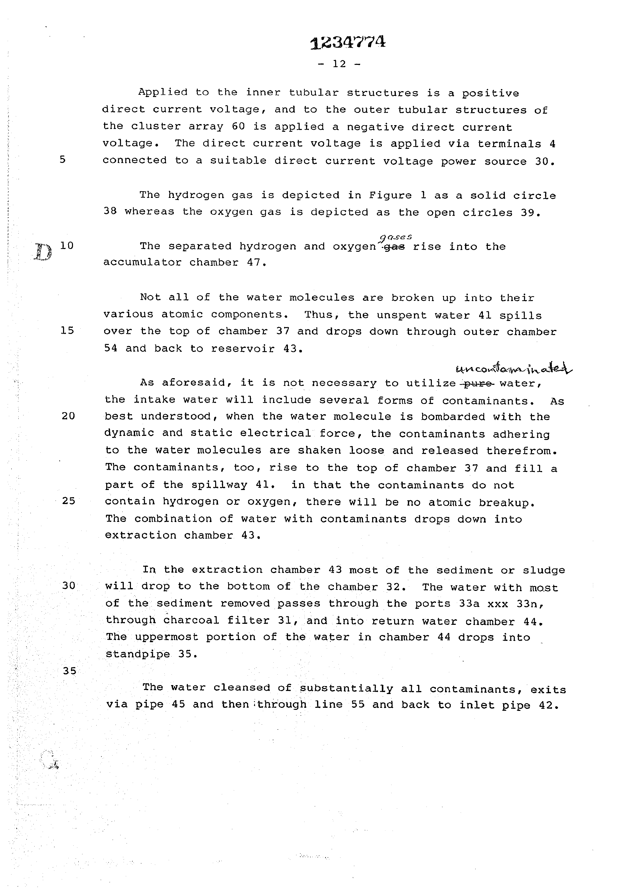
Applied to the inner tubular structures is a positive direct current voltage, and to the outer tubular structures of the cluster array 60 is applied a negative direct current voltage. The direct current voltage is applied via terminals 4
connected to a suitable direct current voltage power source 30.
The hydrogen gas is depicted in Figure 1 as a solid circle 38 whereas the oxygen gas is depicted as the open circles 39.
GES
The separated hydrogen and oxygen”-gas rise into the accumulator chamber 47,
Not ali of the water molecules are broken up into their various atomic components. Thus, the unspent water 41 spills over the top of chamber 37 and drops down through outer chamber 54 and back to reservoir 43.
uncomlaw jroted
As aforesaid, it is not necessary to utilize pure water, the intake water will include several forms of contaminants. As best understood, when the water molecule is bombarded with the dynamic and static electrical force, the contaminants adhering to the water molecules are shaken loose and released therefrom. The contaminants, too, rise to the top of chamber 37 and fill a part of the spillway 41. in that the contaminants do not contain hydrogen or oxygen, there will be no atomic breakup.
The combination of water with contaminants drops down into extraction chamber 43.
_ In the extraction chamber 43 most of the sediment or sludge will drop to the bottom of the chamber 32. The water with most of the sediment removed passes through the ports 33a xxx 33n, through charcoal filter 31, and into return water chamber 44, The uppermost portion of the water in chamber 44 drops into Standpipe 35. .
- The water cleansed of substantially all contaminants, exits via pipe 45 and then ithrough line 55 and back to inlet pipe 42.
Page 15
Drawing sheet — no readable text.

Page 16
TRIAS
THE EMBODIMENTS OF THE INVENTION IN WHICH AN EXCLUSIVE PROPERTY
OR PRIVILEGE IS CLAIMED ARE DEFINED AS FOLLOWS
1. A system for the release of hydrogen and oxygen gas from
natural water having no electrolyte added thereto, comprising:
a housing of non-corrosive, non-reactive, and non-oxidizing material,
Sinai ly ras a pair of’electrical voltage conductive plates simitarly of . Non-corrodable tate .
a non-reactive, nen=corrosive, and non~oxidizing material positioned in said housing with a spatial relationship to
one another,
means for passing said natural water between said plates; and
means connecting one of said plates to a negative output terminal and the other of said Plates to a positive output terminal of a variable D.C. voltage source which includes circuit means for restricting the current thereof to a negligible value relative to the magnitude of the voltage, said voltage forming a positive electrical voltage zone adjacent said plate having said positive terminal connected thereto and a negative voltage zone adjacent said plate having said negative output terminal connected thereto,
voltage when applied to said plates having a sufficient magnitude to cause the hydrogen atoms of the water molecule
to be attracted to said negative zone, and the oxygen atoms to be attracted to said positive zone,
and thereby force the hydrogen atoms and the oxygen atoms to disassociate themselves from the water molecule at a
rate in dependence on the magnitude of the voltage applied to said plates.
Page 17
Vey
2. The system as set forth in claim 1 including
Means selectively to vary the voltage and maintain it at
a constant level.
3. The system as set forth in claim 1 wherein said variable voltage source further comprises pulsing circuit means and wherein the rate of release of said hydrogen
and oxygen gas is directly related to the repetition rate
of the voltage output pulses of said pulsing circuit.
4. The system as set forth in claim 3 wherein the magnitude of the output voltage of said variable voltage source is interrelated to the pulse repetition rate of the output pulse of sand pulsing circuit, and wherein the rate of the hydrogen and oxygen atoms disassociating from the water molecule is related to the magnitude of said
voltage and the pulse repetition rate of said pulses.
5. The system as set forth in claim 1 wherein said variable voltage source includes means for varying the magnitude of said voltage from 0 volts to in excess of 110 volts and for restricting the current thereof to less than 1 ampere.
6. The system as set forth in claim 1, characterized
in that said non-oxidizing plates are coaxial or alternatively
have concentric surfaces.
7. The system as set forth in claim 1, characterized in that said non-oxidizing plates are a plurality of plates
in an array.
8. The system as set forth in claim 1, characterized in that said non-oxidizing plates are a cluster of coaxial plates in an array.
9. The system as set forth in claim 1, characterized in that said non-oxidizing housing further comprises a
gas collection chamber for maintaining a preset volume
of gas under pressure.
Page 18
Bod
10. The system as set forth in claim 7, Characterized by Switching means interconnected to each of said plates in said array and to said voltage source for Switching in and out selected ones of said array of plates from said voltage source.
11. The system as set forth in claim 1 wherein at least one of the spacing between the plates, the length of the plates, the surface area of the plates, the number of plates, the configuration of the plates and the voltage applied to the plates is adapted to be changed so as to alter the production rate of hydrogen and oxygen gas.
12. The system as set forth in claim 1 further comprising means to separate the produced hydrogen and oxygen gases.
13. The process of releasing hydrogen and oxygen gas from natural water having no electrolyte added thereto, comprising:
passing said natural water through a contained area having
a pair of similar non- oxidizing, Ronmeserosive, non-reactive
electrically conductive plates therein,
‘ applying a variable D.C. positive voltage across one of said plates and applying a variable D.C. negative voltage across the other of said plates,
restricting the current of said variable Vora nzes applied
to said plates to a negligible value im—-eonteast to said voltage,
said positive voltage forming a positive voltage zone adjacent said plate having a positive voltage applied thereto and said negative voltage forming a negative
voltage zone adjacent the plate having a negative voltage applied thereto,
said variable voltages applied to said plates being of sufficent magnitude to cause the positive atoms of the water molecule to be attracted to the negative voltage zone
Page 19
and said plate and the negative atoms of the water molecule
to be attracted to the positive voltage zone on said other plate,
thereby forcing the hydrogen atoms and the oxygen atoms to disassociate themselves from the water molecules at a rate
dependent on the magnitude of said variable voltage,
and varying the magnitude of the variable voltage applied to said plates to vary the rate at which the hydrogen atoms and the oxygen atoms disassociate themselves from the water molecule.
14, The process of claim 13 further comprises pulsing the variable voltage applied to said plates at a variable repetition rate and varying the physical parameters of said plates in an interrelationship with said variable voltages.
15. The system as set forth in claim 7 further comprising switching means interconnected to each of said plates in said array and to said voltage source for switching in and out selected ones of said array of plates from said voltage source and wherein the number of said plates having said voltage source switched therein is directly related to the rate of hydrogen atoms and oxygen atoms disassociating from said water molecule.
Page 20
LAMBDA
WYO LLLLLL ELLIO LLL LOCO CON LAN SSS Z g \; ar eek ie ee ~ea a a AL see ee we 0) o °O ft eZ TLLLLLILLILLOLLCLEOLLELOM ZAS SS “2° ow
NSS XS, ey, ) yp tee?
SRP ye 9 0 pern rrr Oe OS) ELS .
<i @ De fe RH | LTRS NS a) we) C2 Lalonkn 5 ARO AY AY A AY {FAY AY A a aa ~ANAN 2 2 we Ce ee er ee eee Ss ao ¢ * ¢
. TL LLLLLELLELRLL LA KLE AAA LL ALAA AA EL LL DES SS AN
ef VT poe eb LL
Page 21
Drawing sheet — no readable text.
Page 22
+ Neekd
BSSASNANSASNSSS SS SSSASSSSSSY
ttn
tas Seater ey
RNAS SASS SAAS AAS. SS SY
Bac ea Sh hee ese Ss ee Sh Sea Snes Shs Se Sins ae
SE FCS ye ee
pcm Yon Yer oe De P, DN bat
RNS SSS Sb ba te
cam San Shean are es Ngee Se Sov the DS Sws Sine Sut Se Shee
Page 23
Drawing sheet — no readable text.
Page 24
Drawing sheet — no readable text.
Page 25
Drawing sheet — no readable text.
Page 26
NOILIGNOD OH
| saws [pe HIOAUASSY 9 VSM [usa — Nivd
TIAM
GaTULSIO
NOLLOVYSLNI OINOI
LNOHLIM NOLWH3INRS = sv9
SGIV SBIVNINVLNOD 0%
GSIVYANIO svo SA NOWLIGNOO O°H “SA YSMOd AVOINLOATS
DLADESE
OPER
Only
>O JeFaqow
OOZMrFIZE
Page 27
MESCro< Oba
CAM ALIA
GAS GENERATED VS. APPLIED VOLTAGE vs.
H5O TEMPERATURE
HO EVAPORATION
/ INCREASE
/ WATER
caren oad
D.C. VOLTAGE APPLIED
(NON- REGULATED; NON-FILTERED)
raanannd & kok ) ~ Vena Pas)
Page 28
OY VBMAPAMZM®A MOP
DMSO
CANAL A
GAS GENERATED VS. EXCITOR TUBE LENGTH
2700 CUBIC INCHES OF GAS ~
PER HOUR
N 456 CUBIC INCHES OF GAS
PER HOUR
EXCITOR TUBE L ENGTH
Ae rnsnwd ok)
Se Sagan)
Page 29
Drawing sheet — no readable text.
Page 30
Drawing sheet — no readable text.
Page 31
Drawing sheet — no readable text.
Page 32
YO OMAPDMZMA WLbo
ANDO
we A TEAL G E
GAS GENERATED VS. ELECTRICAL COST
22,500 CUBIC INCHES OF GAS
S400 CUBIC INCHES OF GAS
2 FT. INTERVALS 10 FT,
EXCITOR LENGTH
——-EXCITOR SURFACE AREA
EXCITOR SIZING
Ceinnaod S Shoes)
Vela AQATS)
Page 33
CLAIM AG A
Jane — aw ie
GAS GENERATED VS. DIFFERENT APPLIED
VOLTAGES VS. H50 CONDITIONS
GAS GENERATED
MP LOAD
VDC
GAS GENERATED
VDC i. AMP LOAD
GAS. GENERATED
voc : AMP. LOAD
DISTILLED CITY WELL OCEAN |
RAIN [77 RIVER J WELL
\— RESERVOIR SALT
TREATED
CONSTANT FLOW HO
Xotroaad A ROK J \ ale aN RENTS)
Page 34
mecro< wpa
CLE EA
GAS GENERATED VS.
PULSE VOLTAGE RATE
VARIABLE <0
PULSE RATE
+ VDC
ON TIME
O voc
FULL 140 PER MINUTE INTERVALS —vecrerse—
TIME
ennnaa Woes, ) we SQA)
Provenance
- Shelf
- Stan Meyer Patents
- Book
- Canadian Patents
- Pages
- 34
- Method
- pdftoppm 300dpi + tesseract 5 (eng)
- Source
- BookStack
- Page Id
- 67
- Transcribed from
- /var/www/html/storage/app/public/archive/documents/6a/6af39d199baa3f97df9ef31c912f39c324a309dac99c2fc66e9ab4dc8f2077ed.pdf