patent · AU8447191
Water fuel injection system
Page 1 — bibliographic record
PCT WORLD INTELLECTUAL PROPERTY ORGANIZATION
International Bureau
INTERNATIONAL APPLICATION PUBLISHED UNDER THE PATENT COOPERATION TREATY (PCT)
(51) International Patent Classification 5 : (11) International Publication Number: WO 92/22679
Coe 2, FOB 51/00 (43) International Publication Date: | 23 December 1992 (23.12.92) (21) International Application Number: PCT/US91/03476 | Published
With international search report.
(71)(72) Applicant and Inventor: MEYER, Stanley, A. [US/US];
3792 Broadway Blvd., Grove City, OH 43123 (US).
(74) Agent: BARANOWSKI, Edwin, M.; Porter, Wright, Morris & Arthur, 41 South High Street, Columbus, OH 43215
(81) Designated States: AT (European patent), AU, BE (European patent), CA, CH (European patent), DE (European patent), DK (European patent), ES (European patent),
FR (European patent), GB (European patent), GR (European patent), IT (European patent), JP, KR, LU (European patent), NL (European patent), SE (European patent), US.
(54) Title: WATER FUEL INJECTION SYSTEM
(57) Abstract
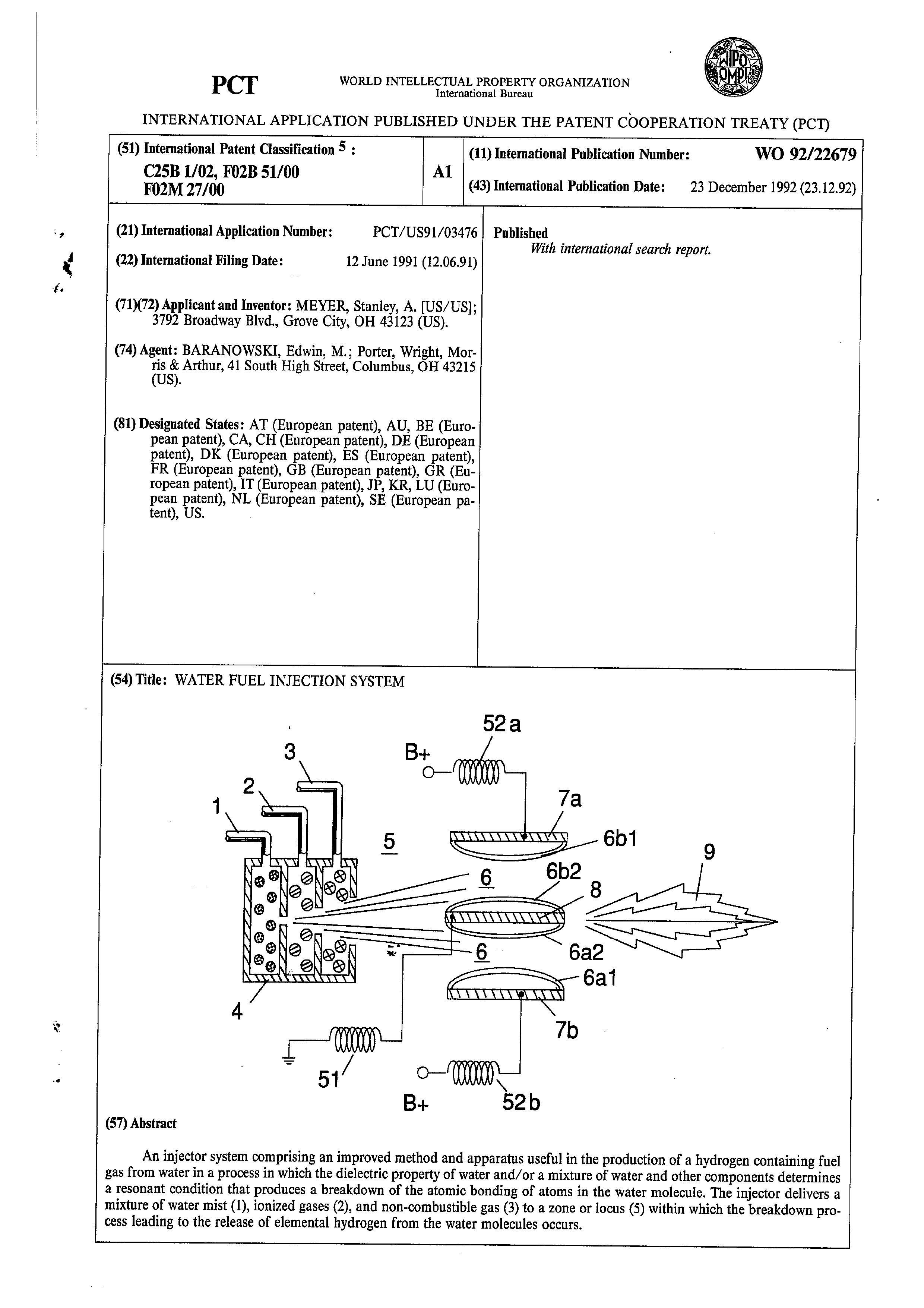
An injector system comprising an improved method and apparatus useful in the production of a hydrogen containing fuel gas from water in a process in which the dielectric property of water and/or a mixture of water and other components determines a resonant condition that produces a breakdown of the atomic bonding of atoms in the water molecule. The injector delivers a mixture of water mist (1), ionized gases (2), and non-combustible gas (3) to a zone or locus (5) within which the breakdown process leading to the release of elemental hydrogen from the water molecules occurs.
Page 2
applications under the PCT.
FOR THE PURPOSES OF INFORMATION ONLY
Codes used to identify States party to the PCT on the front pages of pamphlets publishing international
Austria
Australia
Barbados
Belgium
Burkina Faso Bulgaria
Benin
Brazil
Canada
Central African Republic Congo
Switverland Céte d’lveire Cameroon
Cacchuslovakia Germany
Denmark
Spain
Finland
France
Gabon
United Kingdon Guinea
Greece
Hungary
Iccland
Italy
Japan
Democratic People’s Republic of Korca
Republic of Korea Liechtenstein
Sri Lanka
Luacmbourg
Monaco
Madagascar
Mali
Mongolia
Mauritania
Malawi
Netherlands Norway
Poland
Romania
Russian Federation Sudan
Sweden
Scucgal
Soviet Union
Chad
Togo
United States of America
Page 3
WATER FUEL INJECTION SYSTEM
This invention relates to a method and apparatus useful in producing thermal combustive energy from the hydrogen component of water.
In my patent no. 4,936,961, "Method for the Production of a Fuel Gas," I describe a water fuel cell which produces a gas energy source by a method that utilizes water as a dielectric component of a resonant electrical circuit.
In my patent no. 4,826,581, "Controlled Process for the Production of Thermal Energy From Gases and Apparatus Useful Therefore," I describe a method and apparatus for obtaining the enhanced release of thermal energy from a gas mixture including hydrogen and oxygen in which the gas is subjected to various electrical, ionizing and electromagnetic fields.
In my co-pending application serial no. 07/460,859, "Process and Apparatus for the Production of Fuel Gas and the Enhanced Release of Thermal Energy from Fuel Gas," I describe various means and methods for obtaining the release of thermal/combustive energy from the hydrogen (H) component of a fuel gas obtained from the disassociation of a water (H920) molecule by a process which utilizes the dielectric properties of water in a resonant circuit; and in that application I more thoroughly describe the physical dynamics and chemical aspects of the water-to-fuel conversion process.
The invention of this present application represents a
generational improvement in methods and apparatus useful in
Page 4
In brief, the
the utilization of water as a fuel source.
present invention is a microminiatureized water fuel cell and
permits the direct injection of water, and its simultaneous
transformation into a hydrogen containing fuel, in a combustion zone, such as a cylinder in an internal combustion engine, a jet engine, or furnace. Alternatively the injection system of the present invention may be utilized in any non-engine application in which a concentrated flame or heat source is desired, for example, welding.
The present injection system eliminates the need for an enclosed gas pressure vessel in a hydrogen fuel system and thereby reduces a potential physical hazard heretofore associated with the use of hydrogen-based fuels. The system produces fuel on demand in real-time operation and sets up an integrated environment of optimum parameters so that a water-to-fuel conversion process works at high efficiency.
The preferred embodiment of the invention is more fully
explained below with reference to the drawings in which:
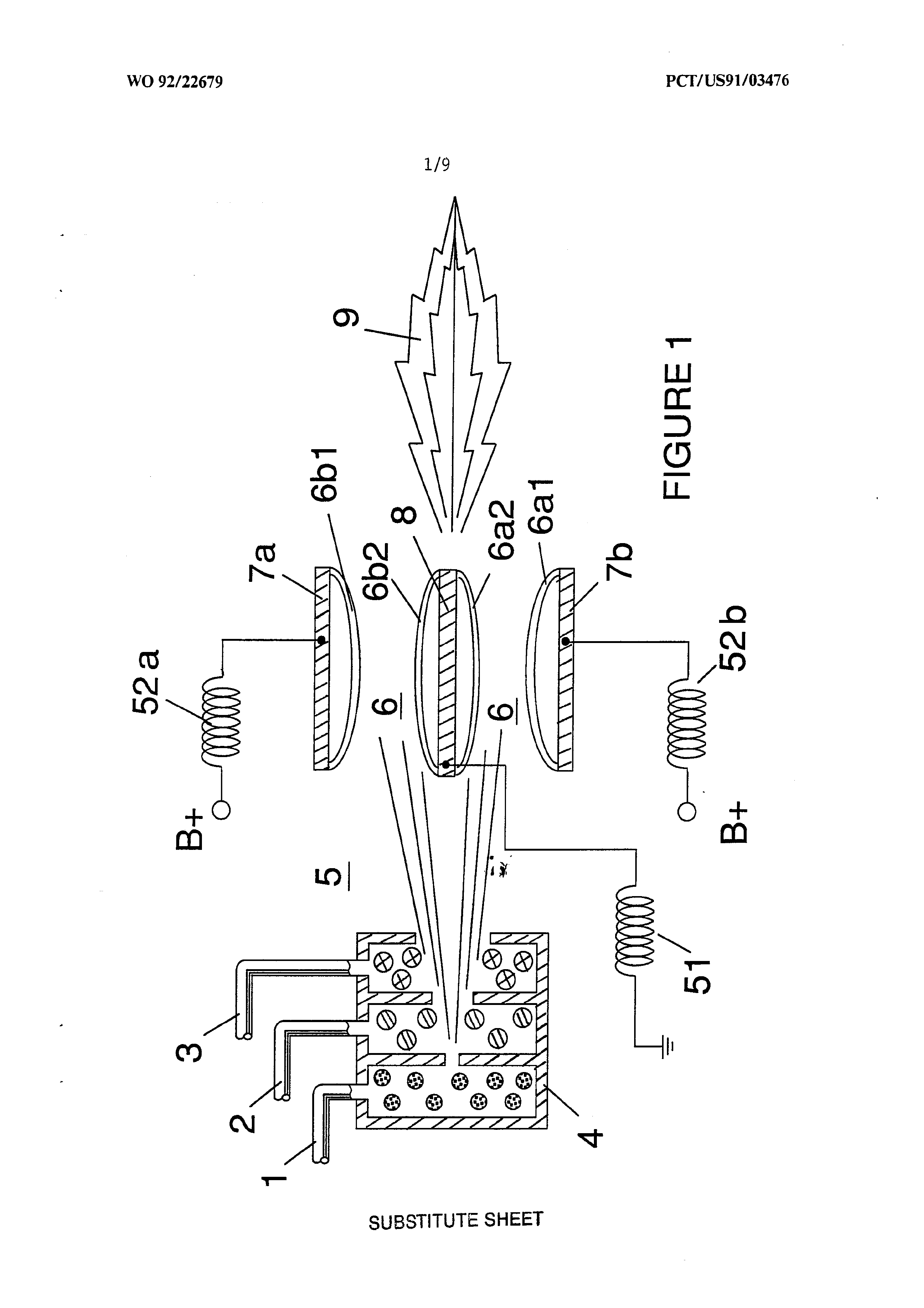
Figure 1 figuratively illustrates the sections and
operating zones included in a single injector of the
invention.
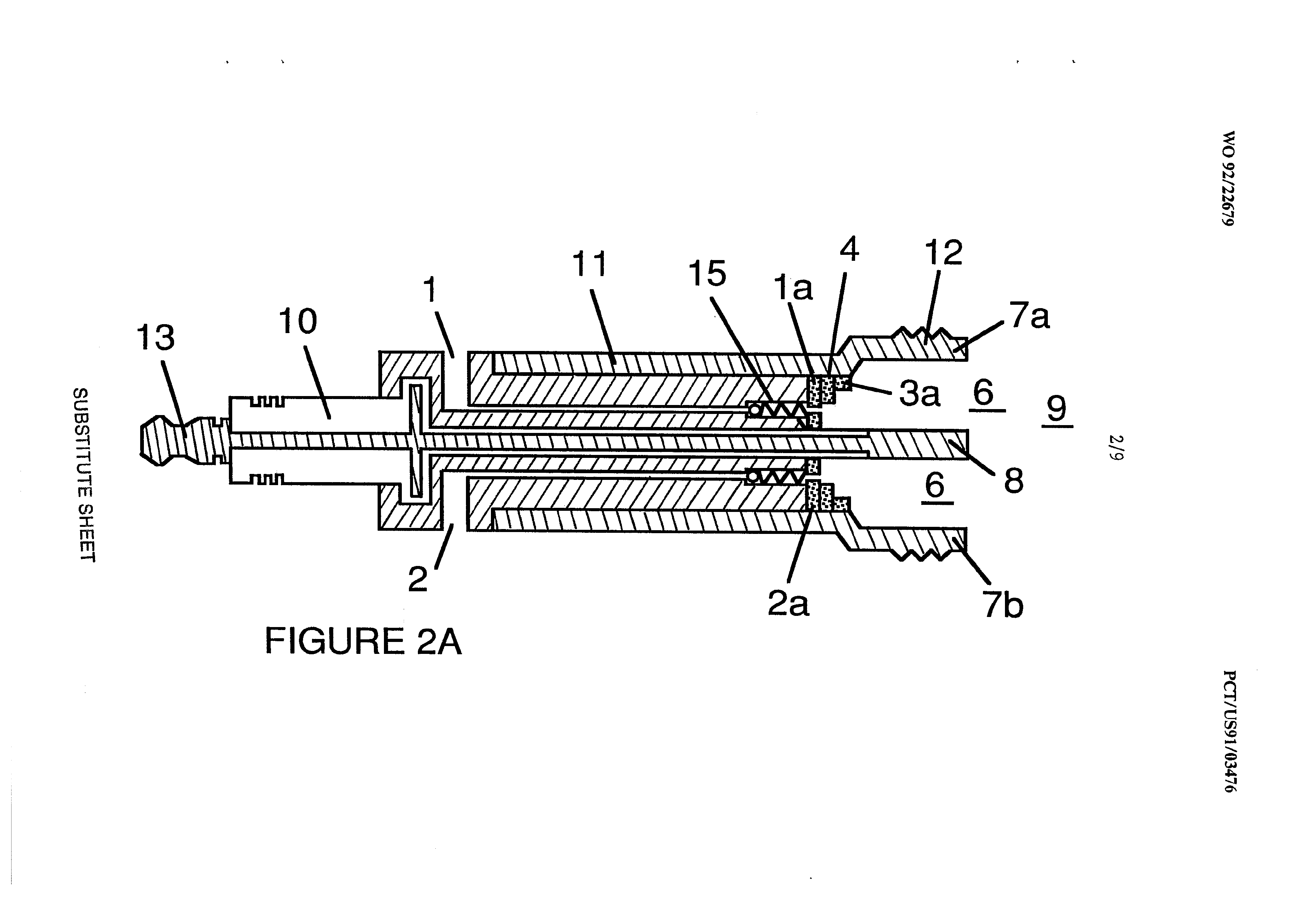
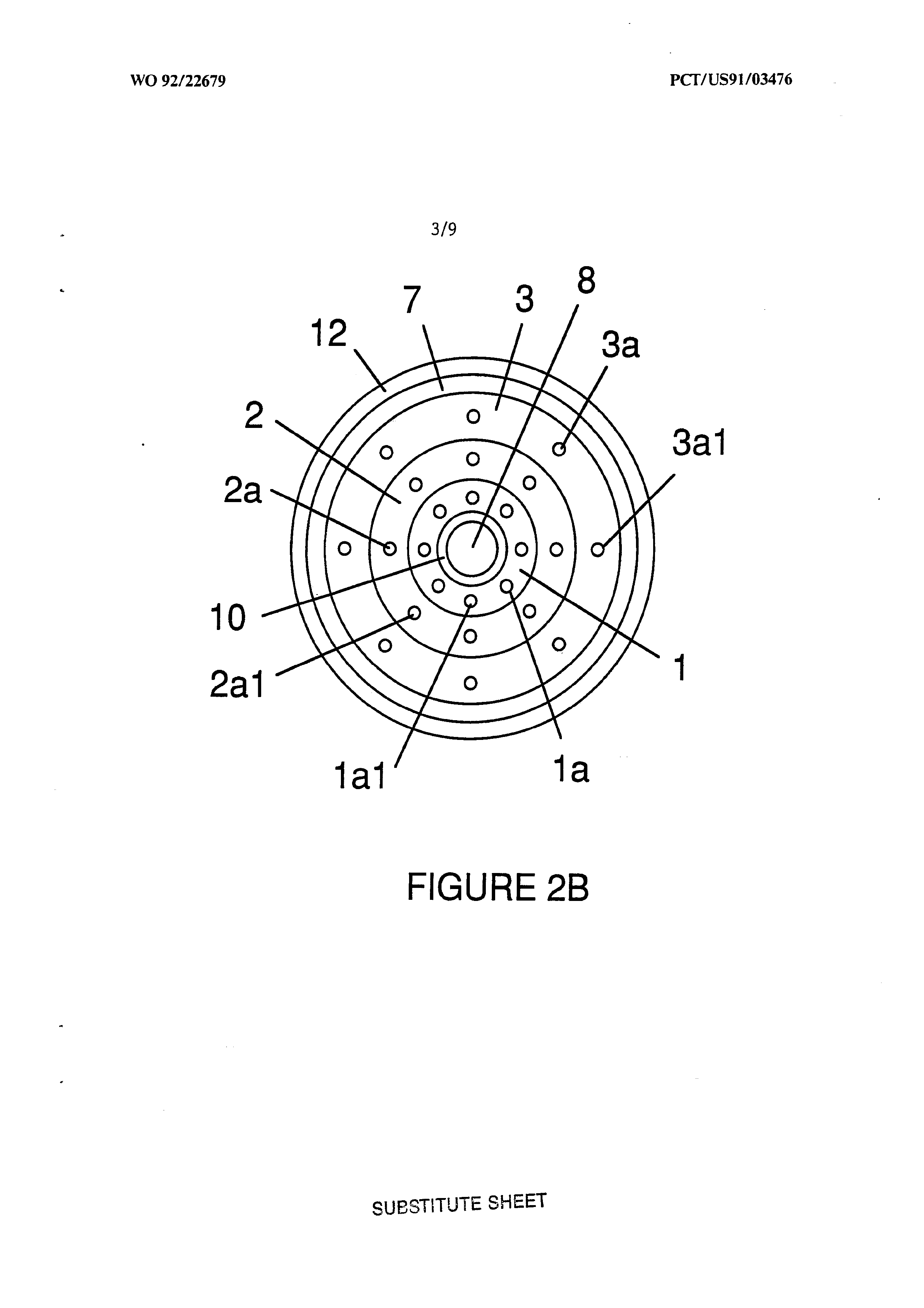
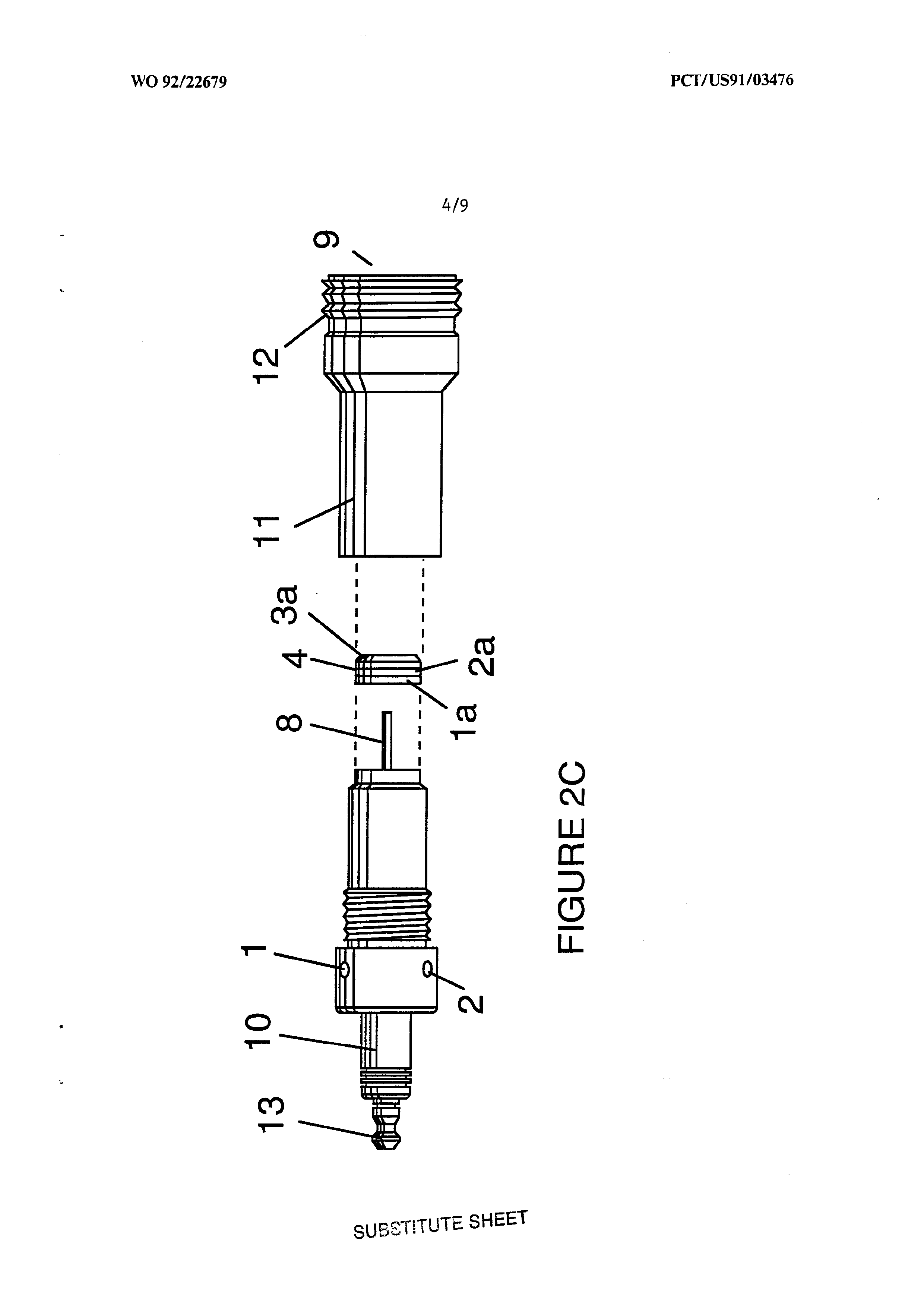
Figure 2A is a side cross sectional view; Figure 2B is a frontal view from the operative end; and Figure
2c is an exploded view -- of an individual injector.
Page 5
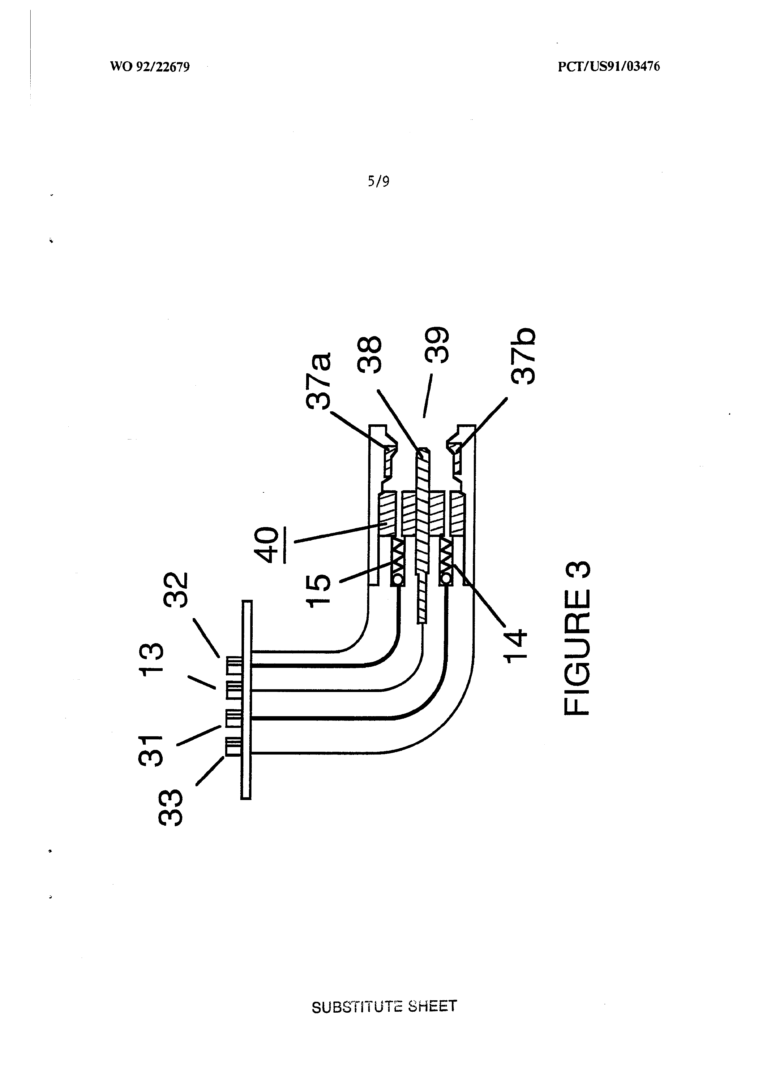
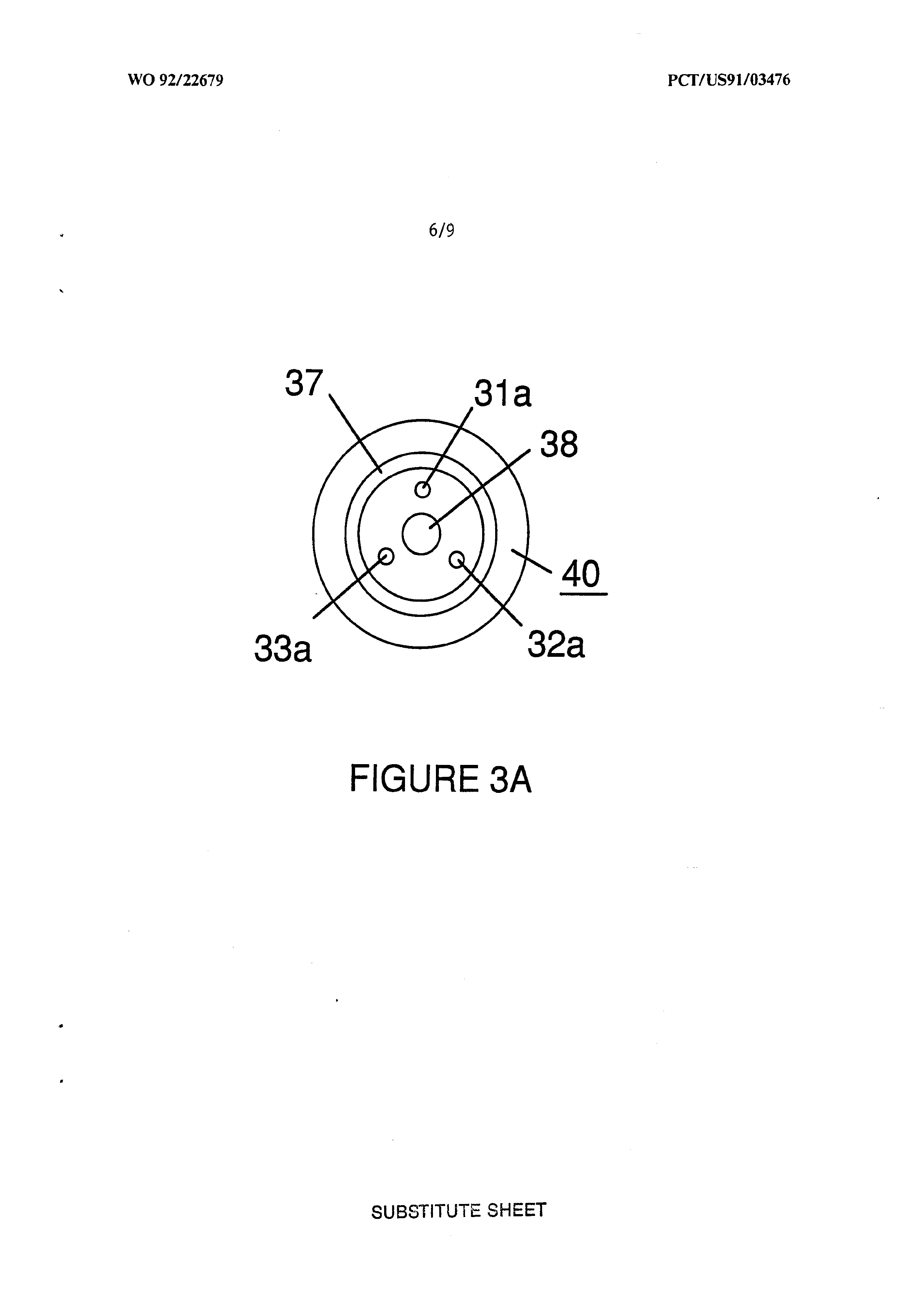
Figure 3A and Figure 3B respectively show a side cross-section view and frontal view of an
alternatively configured injector.
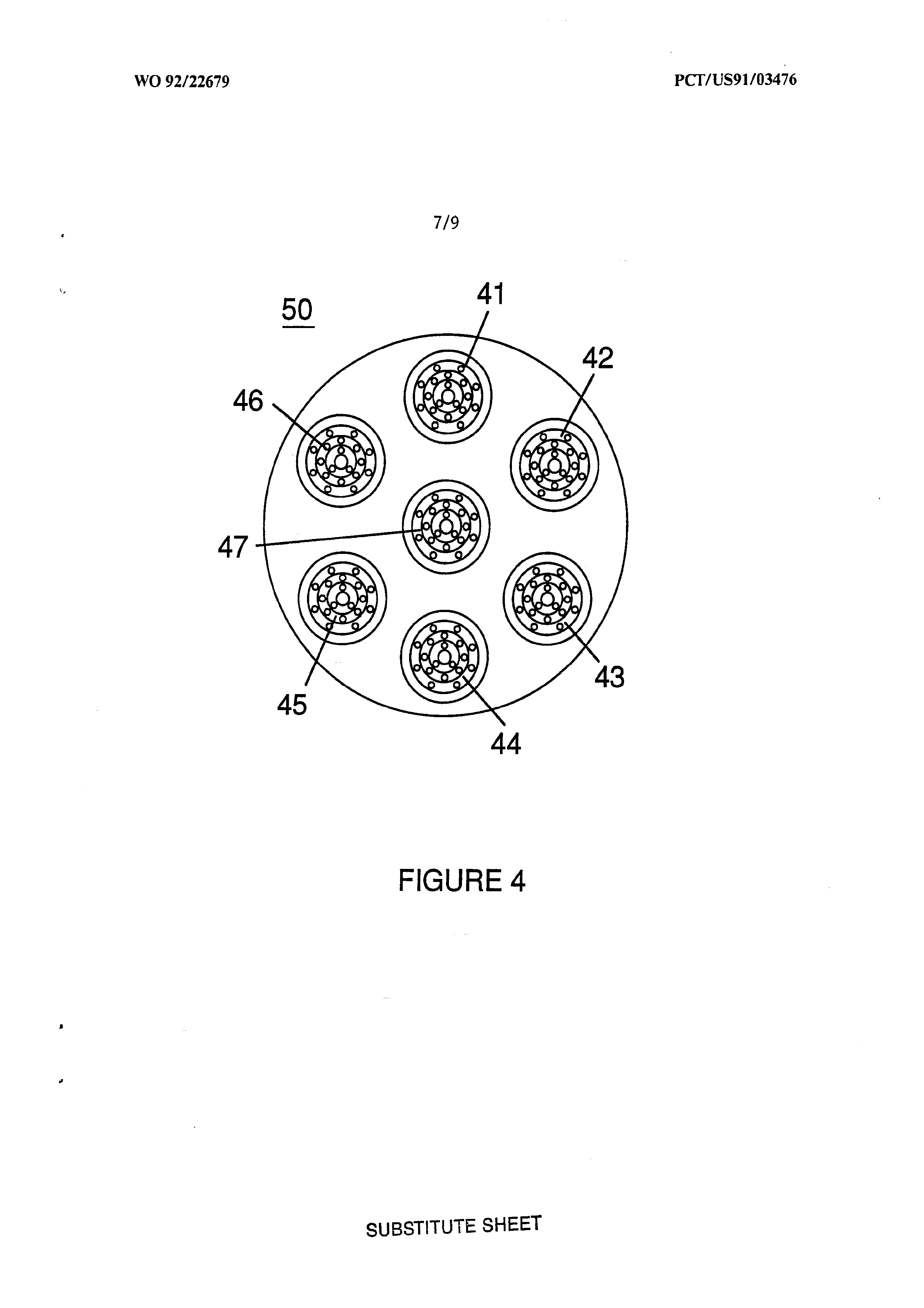
Figure 4 shows a disk array of injectors
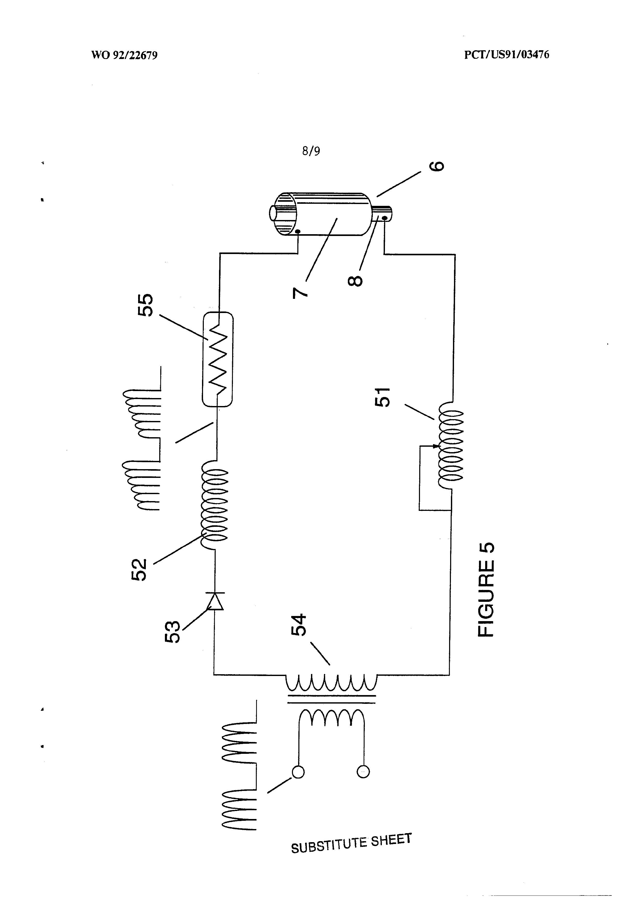
Figure 5 shows the resonance electrical circuit
including the injector.
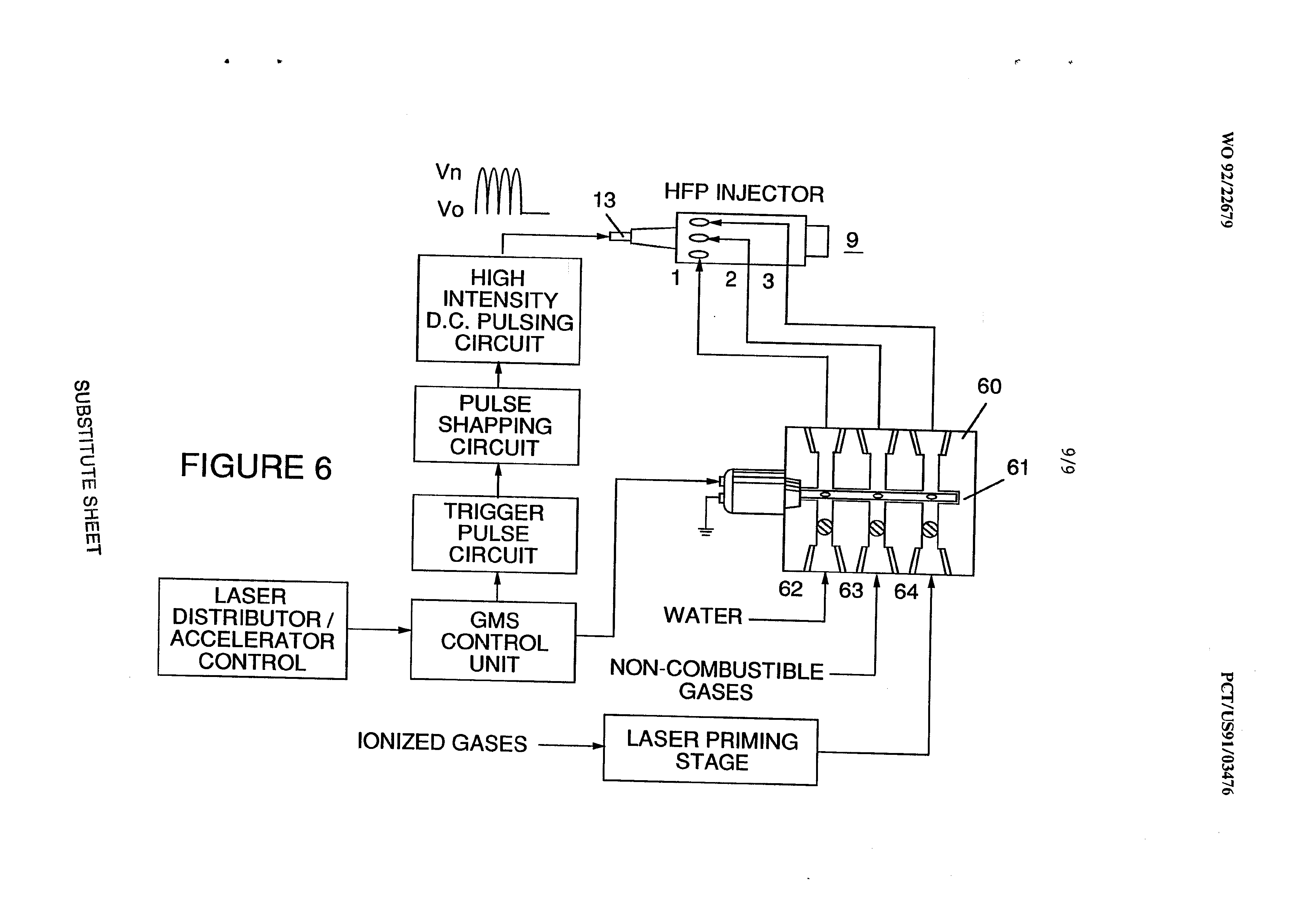
Figure 6 depicts the inter-relationship of the electrical and fuel distribution components of an
injector system.
Although I refer to an “injector” herein, the invention relates not only to the physical configuration of an injector apparatus but also to the overall process. and system parameters determined in the apparatus to achieve the release of thermal energy. In a basic outline, an injector regulates the introduction into a combustion zone of process constituents and sets up a fuel mixture condition permitting combustion. That combustion condition is triggered Simultaneously with injector operation in real time correspondence with control parameters for the process constituents.
In the fuel mixture condition that is created by the injector, water (H20) is atomized into a fine Spray and mixed
with (1) ionized ambient air gases and (2) other
Page 6
non-combustible gases such as nitrogen, argon and other rare gases, and water vapor. (Exhaust gas produced by the combustion of hydrogen with oxygen is a non-combustible water vapor. This water vapor and other inert gases resulting from combustion may be recycled from an exhaust outlet in the injector system back into the input mixture of non-combustible gases.) The fuel mix is introduced at a consistent flow rate maintained under a predetermined pressure. In the triggering of the condition created by the injector, the conversion process described in my patent no. 4,936,961 and co-pending applicaiton serial no. 07/460,859 is set off spontaneously on a "micro" level in a predetermined reaction zone. The injector creates a mixture, under pressure in a definded zone (or locus), of water, ionized gases and non-combustible gases. Pressure is an important factor in the maintenance of the reaction condition and causes the water mist/gas mixture to become intimately mixed, compressed, and destabilized to produce combustion when activated under resonance conditons of ignition. In accordance with the aforementioned converstion process of my patent and application, when water is subjected to a resonance condition water molecules expand and distend; electrons are ejected from the water molecule and absorbed by ionized gases; and the water molecule, thus destabilized, breaks down into its elemental components of hydrogen (2H) and oxygen (0) in the combustion zone. The hydrogen atoms
released from the molecule provide the fuel source in the
Page 7
mixture for combustion with oxygen. The present invention is
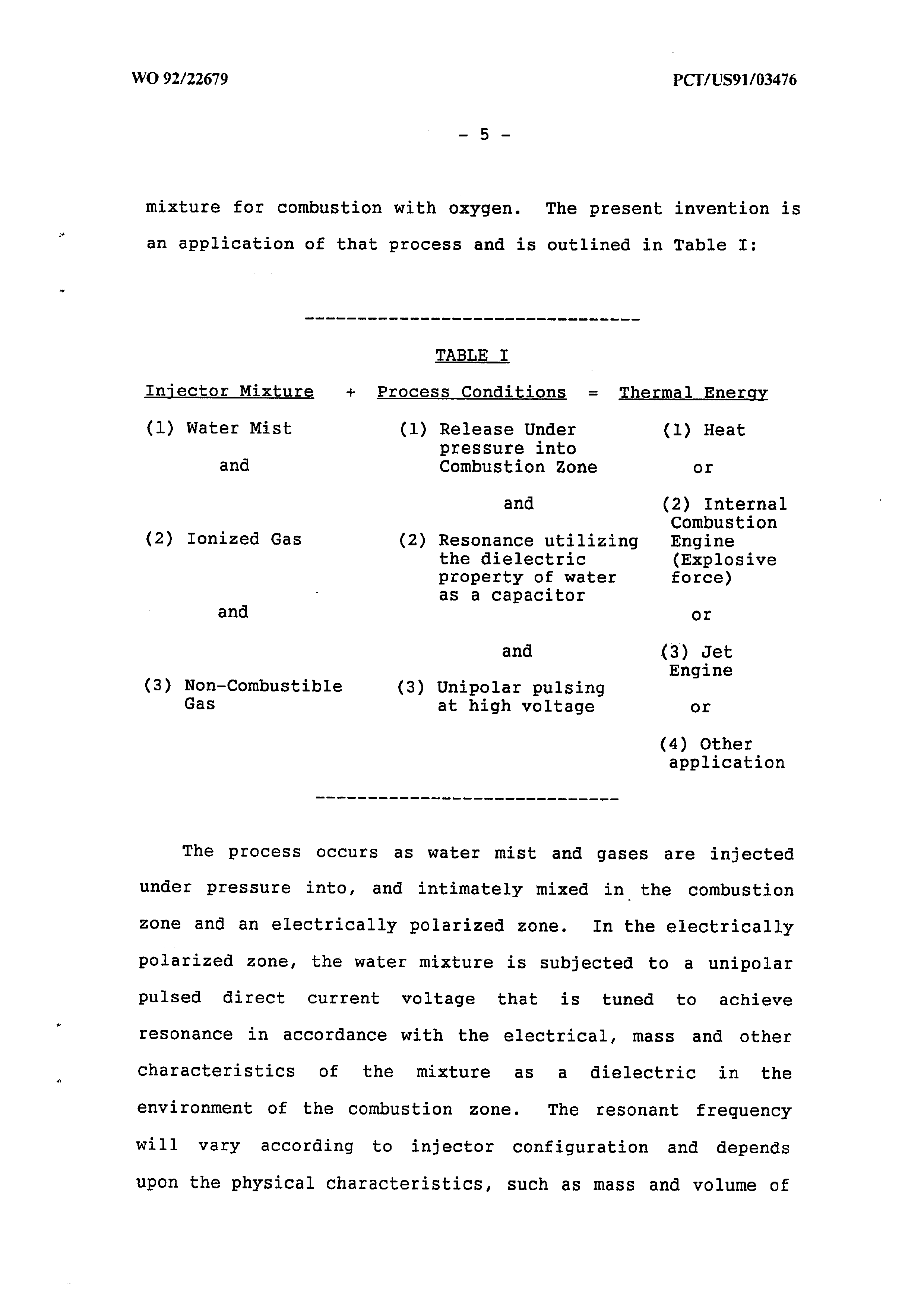
an application of that process and is outlined in Table I:
TABLE I
Injector Mixture + Process Conditions = Thermal Energy (1) Water Mist (1) Release Under (1) Heat pressure into and Combustion Zone or and (2) Internal
Combustion (2) Ionized Gas (2) Resonance utilizing Engine the dielectric (Explosive property of water force) aS a capacitor and or and (3) Jet
Engine (3) Non-Combustible (3) Unipolar pulsing
Gas at high voltage or (4) Other application
The process occurs as water mist and gases are injected under pressure into, and intimately mixed in the combustion zone and an electrically polarized zone. In the electrically polarized zone, the water mixture is subjected to a unipolar pulsed direct current voltage that is tuned to achieve resonance in accordance with the electrical, mass and other Characteristics of the mixture as a dielectric in the environment of the combustion zone. The resonant frequency will vary according to injector configuration and depends
upon the physical characteristics, such as mass and volume of
Page 8
water and gases in the zone. As my prior patents and application point out, the resonant condition in the capacitative circuit is determined by the dielectric
properties of water: (1) as the dielectric in a capacitor
formed by adjacent conductive surfaces and (2) as the water molecule itself is a polar dielectric material. At
resonance, current flow in the resonant electrical circuit
will be minimized and voltage will peak.
The injector system provides a pressurized fuel mixture for subjection to the resonant environment of the voltage combustion zone as the mixture is introduced to the zone. In a preferred embodiment, the injector includes concentrically
nested serial orifices, one for each of three constituent
elements of the fuel mixture. (It may be feasible to combine and process non-combustible and ionized gases in advance of the injector. In this event only two orifices are required, one for the water and the other for the combined gases.) The orifices disperse the water mist and gases under pressure into a conically shaped activation and combustion zone (or locus).
Figure 1A shows a transverse cross-section of an injector in which supply lines for water 1 ionized gas 2 and non-combustible gas 3 feed into a distribution disk assembly 4 having concentrically nested orifices. The fuel mixture passes through a mixing zone 5 and voltage zone 6 created by
electrodes or conductive surfaces 7a and 7b (positive) and 8
(negative or ground). Electrical field lines as shown as 6al
Page 9
and 6a2 and 6bl and 6b2. Combustion (i.e., the oxidation of hydrogen) occurs in the zone 9. Ignition of the hydrogen can be primed by a spark or may occur spontaneously as a result of the exectionally high volatility of hydrogen and its presence in a high voltage field. Although a differentiation of the mixing zone, the voltage zone and the combustion zone is made in explaining the invention, that differentiation relates to events or conditions in a process continuum, and as is evident from Figure 1, the zones are not physically discrete. In the zone(s), there is produced an "excited" mixture of vaporized water mist, ionized gases and other non-combustible gases all of which have been instantaneously released from under high pressure. Simultaneously, the released mixture is exposed to a pulsed voltage in the zone/locus at a frequency corresponding to electrical resonance. Under these conditions, outer shell electrons of atoms in the water molecule are de-stabilized and molecular time share is interrupted. Thus, the gas mixture in the injector zone is subjected to physical, electrical and chemical interactive forces which cause a breakdown of the atomic bonding forces of the water molecule.
Process parameters are determined based on the size of a particular injector. In an injector sized appropriately for use to provide a fuel mixture to a conventional cylinder in a passenger vehicle automobile engine, the injector may resemble a conventional spark plug. In such an injector, the
water orifice is .10 to .15 inch in diameter; the ionized gas
Page 10
orifice is 15 to .20 inch in diameter; and the
non-combustible gas orifice is .20 to .25 inch in diameter.
In such a configuration, the serial orifices increase in size from the innermost orifice, as appropriate to a concentric configuration. As noted above, the introduction of the fuel components is desirably maintained at a constant rate; maintenance of a back pressure of about 125 pounds per square inch for each of the three fuel gas constituents appears satisfactorily useful for a “spark-plug" injector. In the pressurized environment of the injector, spring loaded one-way check valves in each supply line, such as 14 and 15, maintain pressure during pulse off times.
The voltage zone 6 surrounds the pressurized fuel mixture and provides an electrically charged environment of pulsed direct current in the range from about 500 to 20,000 and more volts at a frequency tuned into the resonant characteristic of the mixture. This frequency will typically lie within the range of from about 20KHz to about 50 KHz, dependent, as noted above, on the mass flow of the mixture from the injector and the dielectric property of the mixture. In a spark-plug sized injector, the voltage zone will typically extend longitudinally about .25 to 1.0 inch to permit sufficient dwell time of the water mist and gas mixture between the conductive sufaces 7 and 8 that form a capacitor so that resonance occurs at a high voltage pulsed frequency
and combustion is triggered. In the zone, an energy wave is
formed related to the resonant pulse frequency. The wave
Page 11
continues to pulse through the flame in the combustion zone. The thermal energy produced is released as heat energy. Ina confined zone such as a piston/cylinder engine, gas detonation under resonant conditions produces explosive physical power.
In the voltage zone, the time share ratio of the hydrogen and oxygen atoms comprising the individual water molecules in the water mist is upset in accordance with the process explained in my aforementioned patent no. 4,936,961 and application serial no. 07/460,859. To wit, the water molecule which is itself a polar structure, is distended or distorted in shape by being subjected to the polar electric field in the voltage zone. The resonant condition induced in the molecule by the unipolar pulses upsets the molecular bonding of shell electrons such that the water molecule, at resonance, breaks apart into its constituent atoms. In the voltage zone, the water (H20) molecules are excited into an ionized state; and the pre-ionized gas component of the fuel mixture captures the electrons released from the water molecule. In this manner at the resonant condition, the water molecule is destabilized and the constituent atomic elements of the molecule, 2H and 0, are released; and the released hydrogen atoms are available for combustion. The non-combustible gases in the fuel mixture reduce the burn rate of hydrogen to that of a hydrocarbon fuel such as gasoline or kerosene from its normal burn rate (which is
approximately 2.5 times that of gasoline). Hence’ the
Page 12
presence of non-combustible gases in the fuel mixture moderates energy release and modulate the rate at which the free hydrogen and oxygen molecules combine in the combustion process.
The conversion process does not spontaneously occur and the condition in the zone must be carefully fine tuned to achieve an optimum input flow rate for water and the gases corresponding to the maintenance of a resonant condition. The input water mist and gases may likewise be injected into the zone in a physically pulsed [on/off] manner corresponding to the resonance achieved. In an internal combustion engine, the resonance of the electrical circuit and the physical pulsing of the input mixture may be required to be related to the combustion cycle of the reciprocating engine. In this regard, one or two conventional spark plugs may require a spark cycle tuned in correspondence to the conversion cycle resonance so that combustion of the mixture will occur. Thus, the input flow, conversion rate and combustion rate are interrelated and optimally should each be tuned in accordance with the circuit resonance at which conversion occurs.
The injection system of the present invention is suited to retrofit applications in conventionally fueled gasoline and diesel internal combustion engines and conventionally
fueled jet aircraft engines.
Page 13
EXAMPLE 1
Figures 2A, 2B and 2C illustrate a type of
injector useful, inter alia as a fuel source for
a conventional internal combustion engine. In the cross-section of Figure 2A, reference numerals corresponding to identifying numerals used in Figure 1 show a supply line for water 1 leading to first distribution disc la and supply line for ionized gas 2, leading to second distribution disc 2a. In the cross section, the supply line for non-combustible gas 3 leading to distribution disc 3a is not illustrated, however, its location as a third line should be self-evident. The three discs comprise distribution disc assembly 4. The supply lines are formed in an electrically insulating body 10 surrounded by electrically conductive sheath/housing 11 having a threaded end segment
A central electrode 8 extends the length of the injector. Conductive elements 7a and 7b (7a and 7b depict oppositive sides of the diameter in the cross-section of a circular body) adjacent threaded section 12 form, with electrode 8, the electrical polarization zone 6 proximate to combustion zone 9. An electrical connector 13
may be provided at the other end of the
Page 14
injector. (As used herein “electrode" refers to the conductive surface of an element forming one side of a capacitor.) In the frontal view of Figure 2B it is seen that each disc comprising the distribution disc assembly 9, includes a plurality of micro-nozzles lal, 2al, 3al, etc., for the outlet of the water and gases into the polarization/voltage and combustion zones. The exploded view of Figure 2C shows another view of the injector and additionally depicts two supply line inlets 16 and 17, the third not being shown (because of the inability to represent the uniform 120° separation of three lines in a
two-dimensional drawing).
In the injector, water mist (forming droplets in the range, for example, of from 10 to 250 microns and above, with size being related to voltage intensity) is injected into fuel-mixing and polarizing zone by way of water spray nozzles lal. The tendency of water to form a “bead" or droplet is a parameter related to droplet mist Size and voltage intensity. Ionized air gases and non-combustible gases, introduced through nozzles 2al and 3al, are intermixed with the expelling water mist to form a fuel-mixture which enters into voltage zone 6 where the mixture is
exposed to a pulsating, unipolar high intensity
Page 15
voltage field (typically 20,000 volts at 50 Khz or above at the resonant condition in which current flow in the circuit (amps) is reduced to a minimum) created between electrodes 7 and 8.
Laser energy prevents discharge of the ionized gases and provides additional energy input into the molecular destabilization process that occurs at resonance. It is preferable that the ionized gases be subjected to laser (photonic energy) activiation in advance of the introduction of the gases into the zone(s); although, for example, a fiber optic conduit may be useful to direct photonic enegry directly into the zone. Heat generated in the zone, however, may affect the operability of such an alternative configuration. The electrical polarization of the water molecule and a resonant condition occurs to destablize the molecular bonding of the hydrogen and oxygen atoms. By spark ignition, combustion energy is released.
To ensure proper flame projection and subsequent flame stability, pumps for the ambient air, non-combustible gas and water introduce these components to the injector under static-pressure up to and beyond 125 psi.
Flame temperature is regulated by
controlling the volume flow-rate of each
Page 16
fluid-media in direct relationship to applied voltage intensity. To elevate flame temperature, fluid displacement is increased while the volume flow rate of non-combustible gases is maintained or reduced and the applied voltage amplitude is increased. To lower flame temperature, the fluid flow rate of non-combustible gases is increased and pulse voltage amplitude is lowered. To establish a predetermined flame temperature, the fluid media and applied voltage are adjusted independently. The flame-pattern is further maintained as the ignited, compressed, and moving gases are projected from the nozzle-ports in distribution disc assembly 4 under pressure and the gas expands in the zone and is ignited.
In the voltage zone several functions occur simultaneously to initiate and trigger thermal energy-yield. Water mist droplets are exposed to high intensity pulsating voltage fields in accordance with an electrical polarization process that separates the atoms of the water molecule and causes the atoms to experience electron ejection. The polar nature of the water molecule which facilitates the formation of minute droplets in the mist appears to cause a
relationship between the droplet size and the
voltage required to effect the process, i.e. the
Page 17
greater the droplet size, the higher the voltage required. The liberated atoms of the water molecule interact with laser primed ionized ambient air gases to cause a highly energized and destablized mass of combustible gas atoms. to thermally ignite. Incoming ambient air gases are laser primed and ionized when passing through a gas processor; and an electron extraction circuit (Figure 5) captures and consumes in sink 55 ejected electrons and prevents electron flow into the resonant circuit.
In terms of performance, reliability and safety, ionized air gases and water fuel liquid do not become volatile until the fuel mixture reaches the voltage and combustion zones. Injected non-combustible gases retard and control the combustion rate of hydrogen during gas ignition.
In alternate applications, laser primed ionized liquid oxygen and laser primed liquid hydrogen stored in separate fuel-tanks can be used in place of the fuel mixture, or liquified ambient air gases alone with water can be substituted as a fuel-source.
The injector assembly is design variable and is retrofitable to fossil fuel injector ports
conventionally used in jet/rocket engines, grain
Page 18
dryers, blast furnaces, heating systems, internal
combustion engines and the like.
EXAMPLE IT
A flange mounted injector is shown in cross-section in Figure 3 which shows the fuel mixture inlets and illustrates an alternative three (3) nozzle configuration leading to the polarization (voltage) and combustion zones in which one nozzle 3la, 32a and 33a for each of the three gas mixtures is provided, connected to supply lines 31 and 32 (33 not shown). Electrical polarization zone 36 is formed between electrode 38 and surrounding conductive shell 37. The capacitative element of the resonant circuit is formed when the fuel mixture, as a dielectric, is introduced between the conductive surfaces of 37 and 38. Figure 3A is a frontal
view of the operative end of the injector.
EXAMPLE IIT
Multiple injectors may be arranged in a gang as shown in Figure 4 in which injectors 40, 41,
concentrically in an assembly 50. Such a ganged
Page 19
array is useful in applications having intensive energy requirements such as jet aircraft engines,
and blast furnaces.
EXAMPLE IV
The basic electrical system utilized in the invention is depicted in Figure 5 showing the electrical polarization zone 6 which receives and processes the water and gas mixture’ as a Capacitive circuit element in a resonant charging circuit formed by inductors 51 and 52 connected in series with diode 53, pulsed voltage source 594, electron sink 55 and the zone/locus 6 formed from conductive elements 7 and 8. In this manner, electrodes 7 and 8 in the injector form a Capacitor which has electrical characteristics dependent on the dielectric media (e.qg., the water mist, ionized gases, and non-combustible gases) introduced between the conductive elements. Within the macro-dielectric media, however, the water molecules themselves, because of their polar nature, can he considered
Page 20
EXAMPLE V
Fuel distribution and management systems useful with the injector of this application are described in my co-pending applications for
A distribution block for the assembly is shown in Figure 6. In Figure 6 the distribution block pulses and synchronizes the input of the fuel components in sequence with the electrical pulsing circuit. The fuel components are injected into the injector ports in synchronization with the resonant frequency to enhance the energy wave pulse extending from the voltage zone through the flame. In the configuration of Figure 6, the electrical system is interrelated to distribution block 60, gate valve 61 and separate passageways 62, 63, and 64 for fuel components. The distributor produces a trigger pulse which activates a pulse shaping circuit that forms a pulse having a width and amplitude determined by resonance of the mixture and establishes a dwell time for the mixture in the zone to produce combustion.
As in my referenced application regarding control and management and distribution systems for a hydrogen containing fuel gas produced from
water, the production of hydrogen gas is related
Page 21
to pulse frequency on/off time. In the system shown in Figure 6, the distributor block pulses the fluid media introduced to the injector in relationship to the resonant pulse frequency of the circuit and to the operational on/off gate pulse frequency. In this manner the rate of
water conversion (i.e., the rate of fuel
production by the injector) can be regulated and
the pattern of resonance in the flame controlled.
Page 22
What is claimed is:
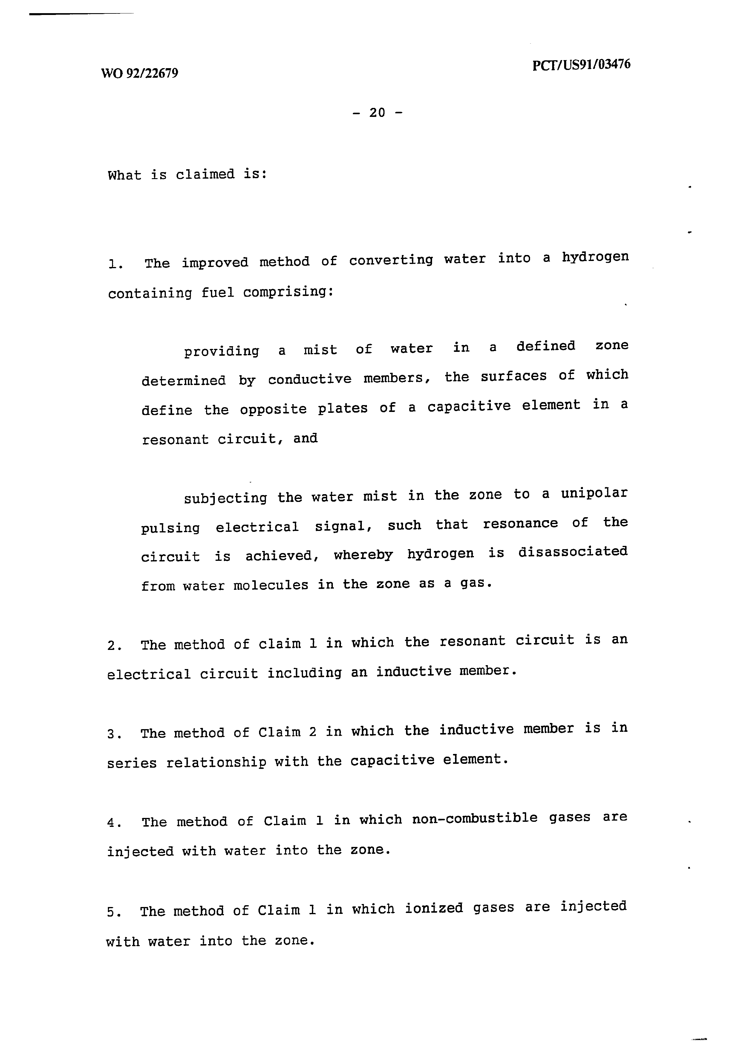
1. The improved method of converting water into a hydrogen containing fuel comprising:
providing a mist of water in a defined zone determined by conductive members, the surfaces of which define the opposite plates of a capacitive element in a resonant circuit, and subjecting the water mist in the zone to a unipolar pulsing electrical signal, such that resonance of the circuit is achieved, whereby hydrogen is disassociated from water molecules in the zone aS a gas.
2. The method of claim 1 in which the resonant circuit is an electrical circuit including an inductive member. 3. The method of Claim 2 in which the inductive member is in series relationship with the capacitive element. 4. The method of Claim 1 in which non-combustible gases are injected with water into the zone.
5. The method of Claim 1 in which ionized gases are injected with water into the zone.
Page 23
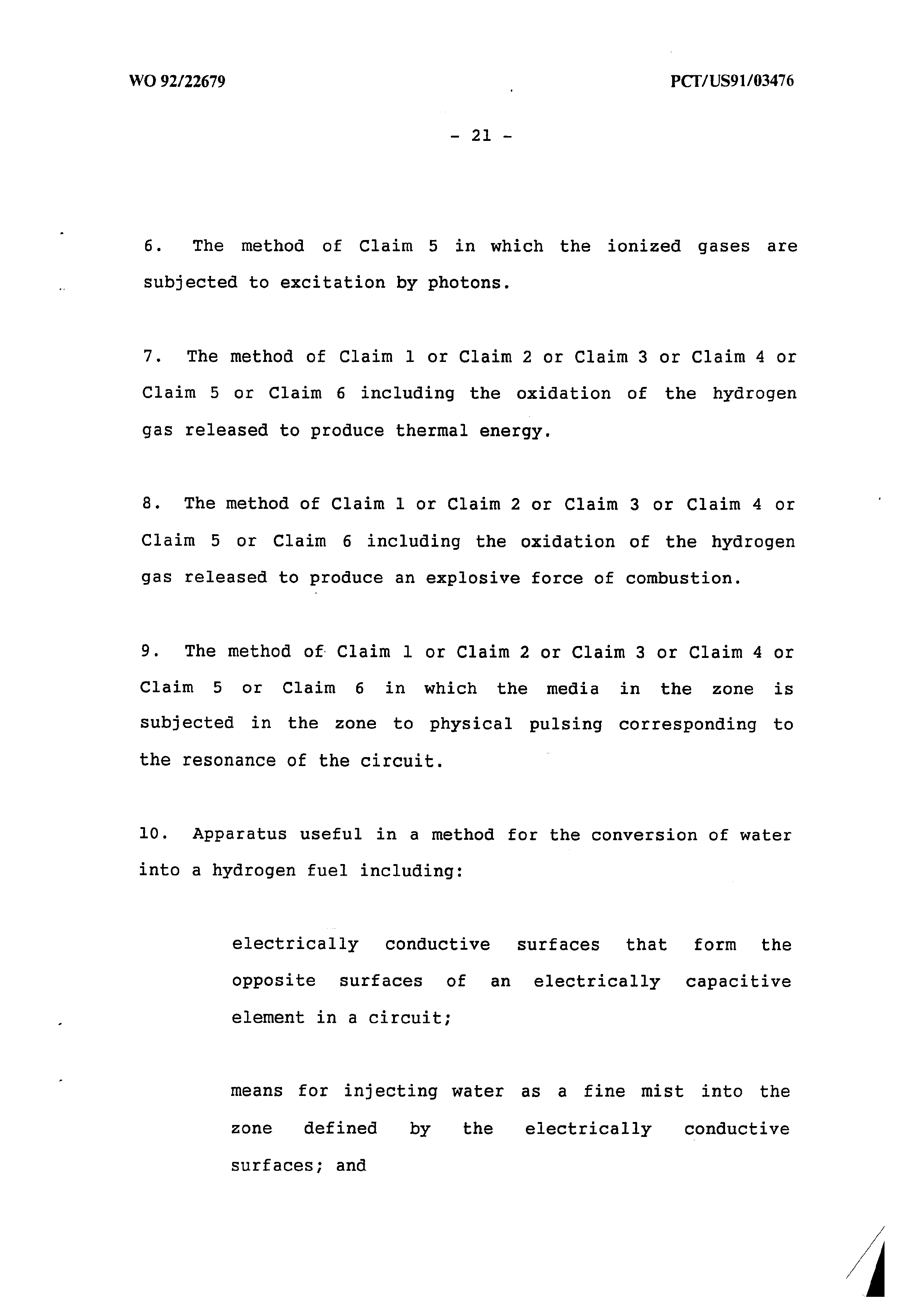
6. The method of Claim 5 in which the ionized gases are subjected to excitation by photons.
7. The method of Claim 1 or Claim 2 or Claim 3 or Claim 4 or Claim 5 or Claim 6 including the oxidation of the hydrogen gas released to produce thermal energy.
8. The method of Claim 1 or Claim 2 or Claim 3 or Claim 4 or Claim 5 or Claim 6 including the oxidation of the hydrogen gas released to produce an explosive force of combustion. 9. The method of Claim 1 or Claim 2 or Claim 3 or Claim 4 or Claim 5 or Claim 6 in which the media in the zone is subjected in the zone to physical pulsing corresponding to the resonance of the circuit.
10. Apparatus useful in a method for the conversion of water into a hydrogen fuel including:
electrically conductive surfaces that form the opposite surfaces of an electrically capacitive element in a circuit;
means for injecting water as a fine mist into the zone defined by the electrically conductive surfaces; and
Page 24
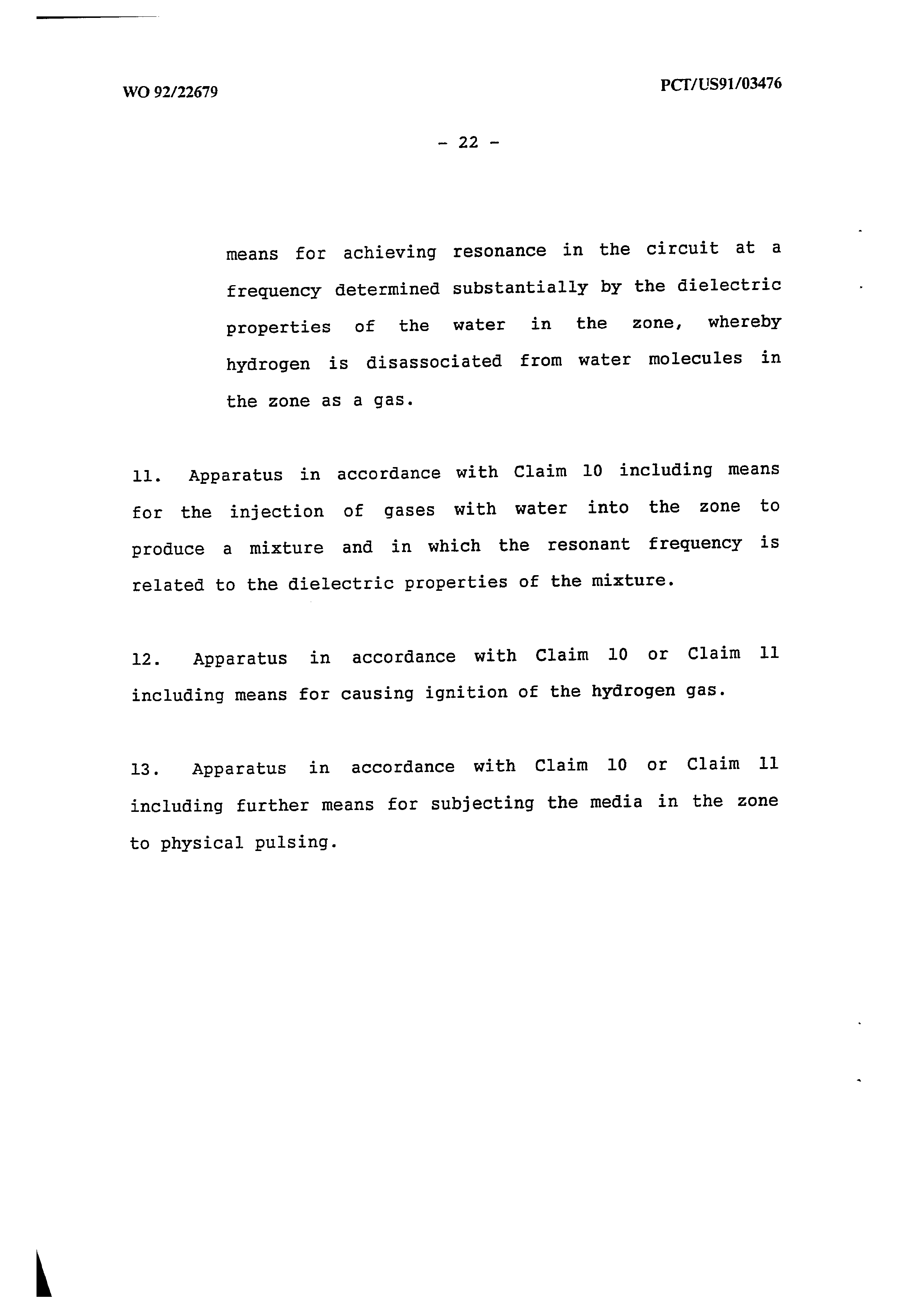
means for achieving resonance in the circuit at a frequency determined substantially by the dielectric properties of the water in the zone, whereby
hydrogen is disassociated from water molecules in
the zone aS a gas.
11. Apparatus in accordance with Claim 10 including means for the injection of gases with water into the zone to produce a mixture and in which the resonant frequency is
related to the dielectric properties of the mixture.
12. Apparatus in accordance with Claim 10 or Claim 11
including means for causing ignition of the hydrogen gas.
13. Apparatus in accordance with Claim 10 or Claim il including further means for subjecting the media in the zone
to physical pulsing.
Page 25
Drawing sheet — no readable text.
Page 26
LSSHS SLNLILSANS
Ly ) rebel Ot le MILLLLLLLLLLLA XS fst — 3a ava,
POT IT TIT TTT TTT TTT TT F
Qt IAHLNALESERERURERTEURRTERSORTETENNNUU PELLLLLL LLL LLL LLL Lh i a LLL VTIVITL LI 11k, = C8
FIGURE 2A
Page 27
Drawing sheet — no readable text.
Page 28
Drawing sheet — no readable text.
Page 29
Drawing sheet — no readable text.
Page 30
Drawing sheet — no readable text.
Page 31
Drawing sheet — no readable text.
Page 32
Drawing sheet — no readable text.
Page 33
FIGURE 6
LASER
DISTRIBUTOR /
ACCELERATOR
CONTROL
INTENSITY
D.C. PULSING
CIRCUIT
PULSE
SHAPPING
CIRCUIT
TRIGGER
PULSE
CIRCUIT
GMS
CONTROL
UNIT
lONIZED GASES
HFP INJECTOR
WATER
GASES
LASER PRIMING
STAGE
Page 34
‘INTERNATIONAL SEARCH REPORT
International Application No. PCT/US91/03476 |. CLASSIFICATION OF SUBJECT MATTER (if several classification symbols apply, indicate all) &
According to International Patent Classification rf todo ation jassification an
lt. FIELDS SEARCHED
“Minimum Oocumentation Searched 7
Classification System . Classification Symools
Documentation Searched other than Minimum Documentation to the Extent that such Documents are Included in the Fields Searched ®&
ll, DOCUMENTS CONSIDERED TO BE RELEVANT ®
Relevant to Claim No. '3
Category °* Citation of Document, '' with indication, where appropriate, of the relevant passages '2
See entire document. 10,12,13
See entire document.
See entire document. .
See entire document.
See Abstract.
See figure and document.
See entire document.
* Spacial categories of cited documents: 1°
“A" document defining the generai state of the art which :@ not considered to be of particular relevance
"€" earlier document but published on or after the international filing date
“LC document which may throw doubts on priority claim(s) or which is cited to establish-the publication date of another citation or other special reason (as specified)
“Q" document referring to an oral disclosure, use, exhibition or other means
“P" document published prior to the international filing cate but later than the priority date claimed
“T" later document published after the international filing date or priority date and not in conflict with the application but cited to understand the principie or theory underlying the invention
“X" document of particular rel : the cl inventi cannot be considered novel or cannot be considered to involve an inventive step
“¥" document of particular relevance; the claimed invention cannot be considered to invoive an inventive step when the document is combined with one or more other such documents. such combination being obvious to a person skilled in tne a
"&" document member of the same patent family
IV. CERTIFICATION
Date of the Actuai Completion of the International Search
: Date of Mailing of this International Search Report
International Searching Authority
Signature of Authorized Officer [vente frgeuper_ ores oet NGOC-HO
| STEVEN P. MARGUIS .:". -~aaATIONALDIVESPON
Form PCTASA210 (escand sheed (Riev.11-87)
Page 35
International Aoplieation No. PCT /US9L {03476
FURTHER INFORMATION CONTINUED FROM THE SECOND SHEET
See entire document.
See entire document.
See entire document.
v oO OBSERVATIONS WHERE CERTAIN CLAIMS WERE FOUND UNSEARCHAGLE '
This international search report has not been established in respect of certain claims under Article 17(2) (a) for the following reasons:
1. Claim numbers because they relate to subject matter +? not required to be searched by this Authority, namely:
2.0] Claim numbers _.. _ . because they relate to parts of the international application that do not comply with the prescribed requirements to such an extent that no meaningful international search can be carried out 15, specifically:
30 Claim numbers, , because they are dependent claims not drafted in accordance with the second and third sentences of PCT Rule 6.4(a).
vit] OBSERVATIONS WHERE UNITY OF INVENTION IS LACKING?
This International Searching Authority found multiple inventions in this international application as follows;
10] As ail required additional search fees were timely paid by the applicant, this international search report covers all searchable claims of the international application.
20] As only some of the required additional search fees were timely paid by the applicant, this international search report covers only those claims of the International application for which fees were paid, specifically claims:
3 No required additional search fees were timely paid by the applicant. Consequently, this international search report Is restricted to the invention first mentioned in the claims; it is covered by claim numbers:
4. As all searchable claims could be searchad without effort justifying an additional fee, the International Searching Authority did not invite payment of any additional fee. .
Remark on Protest oO The additional search fees were accompanied by applicant's protest.
oO No protest accompanied the payment of additional search fees.
Fonn PCTASAZ10 (suppirnertal sheet (2) (Rev. 11-87)
Provenance
- Shelf
- National filings
- Filed
- 1991-06-12
- Method
- pdftoppm 300dpi + tesseract 5 (eng), orientation-corrected
- Source
- The international pamphlet as held in the Australian file; it carries no Australian markings
- Entered From
- WO9222679A1
- Office Number
- AU-A-84471/91
- Classification
- C25B 1/02; F02B 51/00; F02M 27/00
- Application Number
- PCT/US91/03476
- International Published
- 1992-12-23