patent · AU7485291
Control and driver circuits for a hydrogen gas fuel producing cell
Page 1 — bibliographic record
PCT WORLD INTELLECTUAL PROPERTY ORGANIZATION
International Bureau
INTERNATIONAL APPLICATION PUBLISHED UNDER THE PATENT COOPERATION TREATY (PCT)
(51) International Patent Classification 5 : (11) International Publication Number: WO 92/07861 C07G 13/00, HO3K 3/30 Al (43) International Publication Date: 14 May 1992 (14.05.92)
(21) International Application Number: PCT/US90/06407 | Published With international search report.
(22) International Filing Date: 2 November 1990 (02.11.90)
(71}(72) Applicant and Inventor: MEYER, Stanley, A. [US/US]; 3792 Broadway, Grove City, OH 43123 (US).
(74) Agent: BARANOWSKI, Edwin, M.; Porter, Wright, Morris & Arthur, 41 South High Street, Columbus, OH 43215
(81) Designated States: AT (European patent), AU, BE (European patent), CA, CH (European patent), DE (European patent), DK (European patent), ES, ES (European patent), FR (European patent), GB (European patent), GR (European patent), IT (European patent), JP, KR, LU (European patent), NL (European patent), SE (European patent), US.
(54) Title: A CONTROL AND DRIVER CIRCUITS FOR A HYDROGEN GAS FUEL PRODUCING CELL
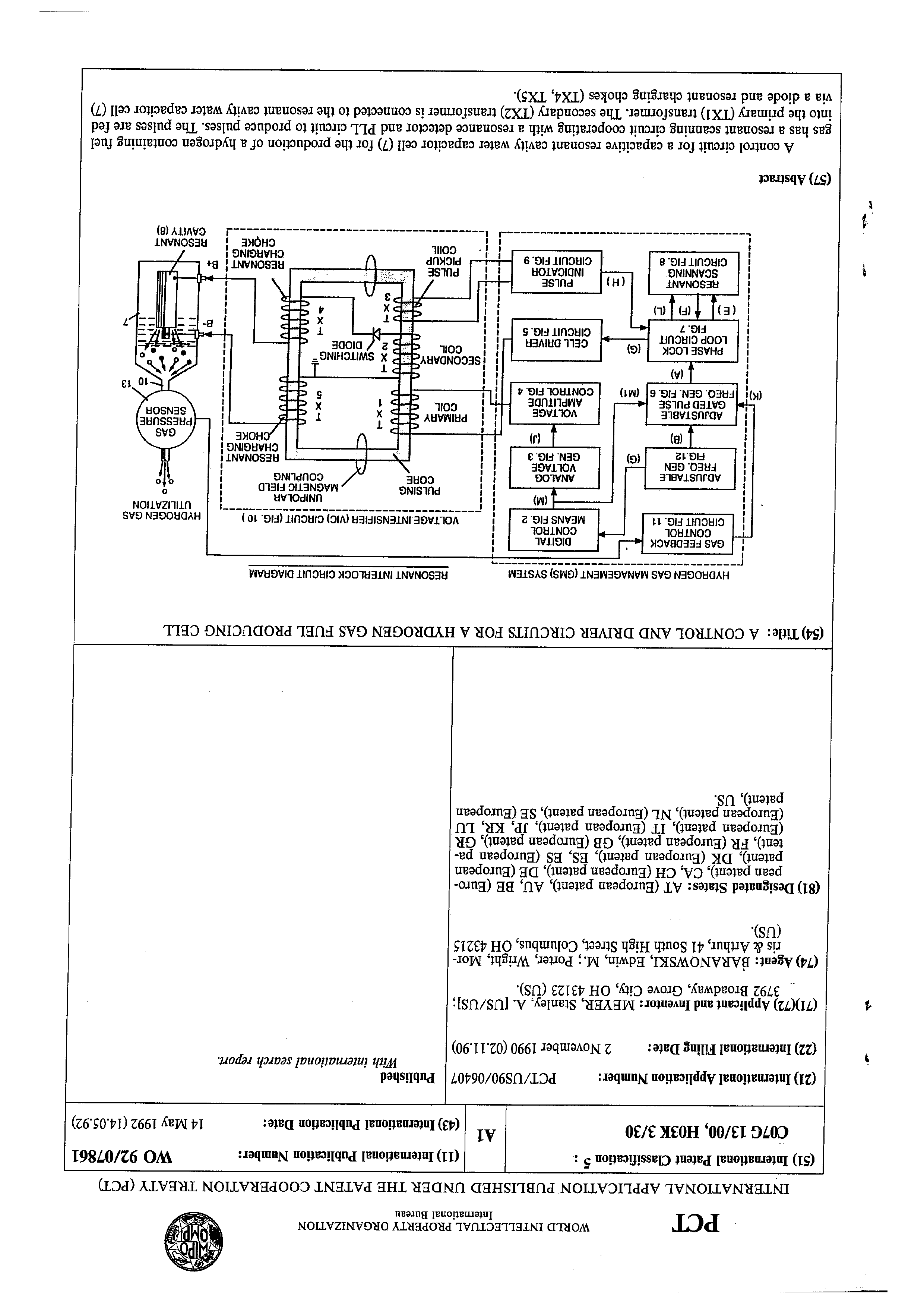
HYDROGEN GAS MANAGEMENT (GMS) SYSTEM RESONANT INTERLOCK CIRCUIT DIAGRAM
GAS FEEDBACK
CONTROL
CIRCUIT FIG. 11
DIGITAL
CONTROL
MEANS FIG. 2
HYDROGEN GAS
ee ee ee ene UTILI
UNIPOLAR ZATION
MAGNETIC FIELD
COUPLING
RESONANT
CHARGING
ANALOG
VOLTAGE
GEN. FIG. 3
ADJUSTABLE
FREQ. GEN
GAS
PRESSURE
SENSOR
ADJUSTABLE
GATED PULSE
FREQ. GEN. FIG. 6
VOLTAGE
AMPLITUDE
CONTROL FIG. 4
PHASE LOCK
LOOP CIRCUIT
FIG. 7
RESONANT
SCANNING
CIRCUIT FIG. 8
PULSE
INDICATOR
CIRCUIT FIG. 9
RESONANT | B+
oP CHARGING |
CHOKE | RESONANT
tne AV ect CAVITY (8)
(57) Abstract
A control circuit for a capacitive resonant cavity water capacitor cell (7) for the production of a hydrogen containing fuel gas has a resonant scanning circuit cooperating with a resonance detector and PLL circuit to produce pulses. The pulses are fed into the primary (TX1) transformer. The secondary (TX2) transformer is connected to the resonant cavity water capacitor cell (7)
via a diode and resonant charging chokes (TX4, TX5).
| wees
Page 2
FOR THE PURPOSES OF INFORMATION ONLY
Codes used to identify States party to the PCT on the front pages of pamphlets publishing international applications under the PCT.
AT Austria ES Spain . MG Madagascar
AU Australia Fi Finland ML Mali
BB Barbados FR France MN Mongolia
BE Belgium GA Gabon MR Mauritania
BF Burkina. Faso GB United Kingdom MW Malawi
BG Bulgaria GN Guinea NL Netherlands
BJ Benin GR Greece NO Norway
BR Brazil HU Hungary PL Poland
CA Canada IT italy RO Romania
cF Central Africun Republic Je Japan sD Sudan
cG Congo KP Democratic People’s Republic SE Sweden
CH Switzerland of Korea SN Senegal
ci Cate d'Ivoire KR Republic of Korca sut* Sovict Union cM Cameroon LI Liechtenstein TD Chad
cs Czechoslovakia LK Sri Lanka TG Togo
DE* Germany . LU Luxembourg us United States of America DK Denmark MC Monaco.
+ Any designation of “SU” has effect in the Russian Federation. It is not yet known whether any such designation has effect in other States of the former Soviet Union.
Page 3
CONTROL AND DRIVER CIRCUITS FOR
A HYDROGEN GAS FUEL PRODUCING CELL
This invention relates to electrical circuit systems useful in the operation of a water fuel cell including a water capacitor/resonant cavity for the production of a hydrogen containing fuel gas, such as that described in my United States Letter Patent No. 4,936,961, "Method for the Production of a Fuel Gas", issued on June
In my aforesaid Letters Patent for a method for the production of a fuel gas, voltage pulses applied to plates of a water capacitor tune into the dielectric properties of the water and attenuate the electrical forces between the hydrogen and oxygen atoms of the molecule. The attenuation of the electrical forces results in a change in the molecular electrical field and the covalent atomic bonding forces of the hydrogen and oxygen atoms. When resonance is achieved, the atomic bond of the molecule is broken, and the atoms of the molecule disassociate. At resonance, the current (amp) draw from a power source to the water capacitor is minimized and voltage across the water capacitor increases. Electron £low is not permitted (except at the minimum, corresponding to leakage resulting from the residual conductive properties of water). For the process to
continue, however, a resonant condition must be
maintained.
Page 4
Because of the electrical polarity of the water molecule, the fields produced in the water capacitor respectively attract and repel the opposite and like charges in the molecule, and the forces eventually achieved at resonance are such that the strength of the covalent bonding force in the water molecule is exceeded, and the atoms of the water molecule (which are normally in an electron sharing mode) disassociate. Upon disassociation, the formerly shared bonding electrons migrate to the hydrogen nuclei, and both the hydrogen and oxygen revert to net zero electrical charge. The atoms are released from the water as a gas mixture.
In the invention herein, a control circuit for a resonant cavity water capacitor cell utilized for the production of a hydrogen containing fuel gas is provided.
The circuit includes an isolation means such as a transformer having a ferromagnetic, ceramic or other electromagnetic material core and having one side of a secondary coil connected in series with a high speed switching diode to one plate of the water capacitor of the resonant cavity and the other side of the secondary coil connected to the other plate of the water capacitor to form a closed loop electronic circuit utilizing the dielectric properties of water as part of the electronic resonant circuit. The primary coil of the isolation transformer is connected to a pulse generation means. The
secondary coil of the transformer may include segments
Page 5
that form resonant charging choke circuits in series with the water capacitor plates.
In the pulse generation means, an adjustable first, resonant frequency generator and a second gated pulse frequency generator are provided. A gate pulse controls the number of the pulses produced by the resonant frequency generator sent to the primary coil during a period determined by the gate Frequency of the second pulse generator.
The invention also includes a means for sensing the occurrence of a resonant condition in the water capacitor/resonant cavity, which when a ferromagnetic or electromagnetic core is used, may be a pickup coil on the transformer core. The sensing means is interconnected to a scanning circuit and a phase lock loop circuit, whereby the pulsing frequency to the primary coil of the transformer is maintained at a sensed frequency corresponding to a resonant condition in the water capacitor.
Control means are provided in the circuit for adjusting the amplitude of a pulsing cycle sent to the primary coil and for maintaining the frequency of the pulsing cycle at a constant frequency regardless of pulse amplitude. In addition, the gated pulse frequency generator may be operatively interconnected with a sensor that monitors the rate of gas production from the cell and
controls the number of pulses from the resonant frequency
Page 6
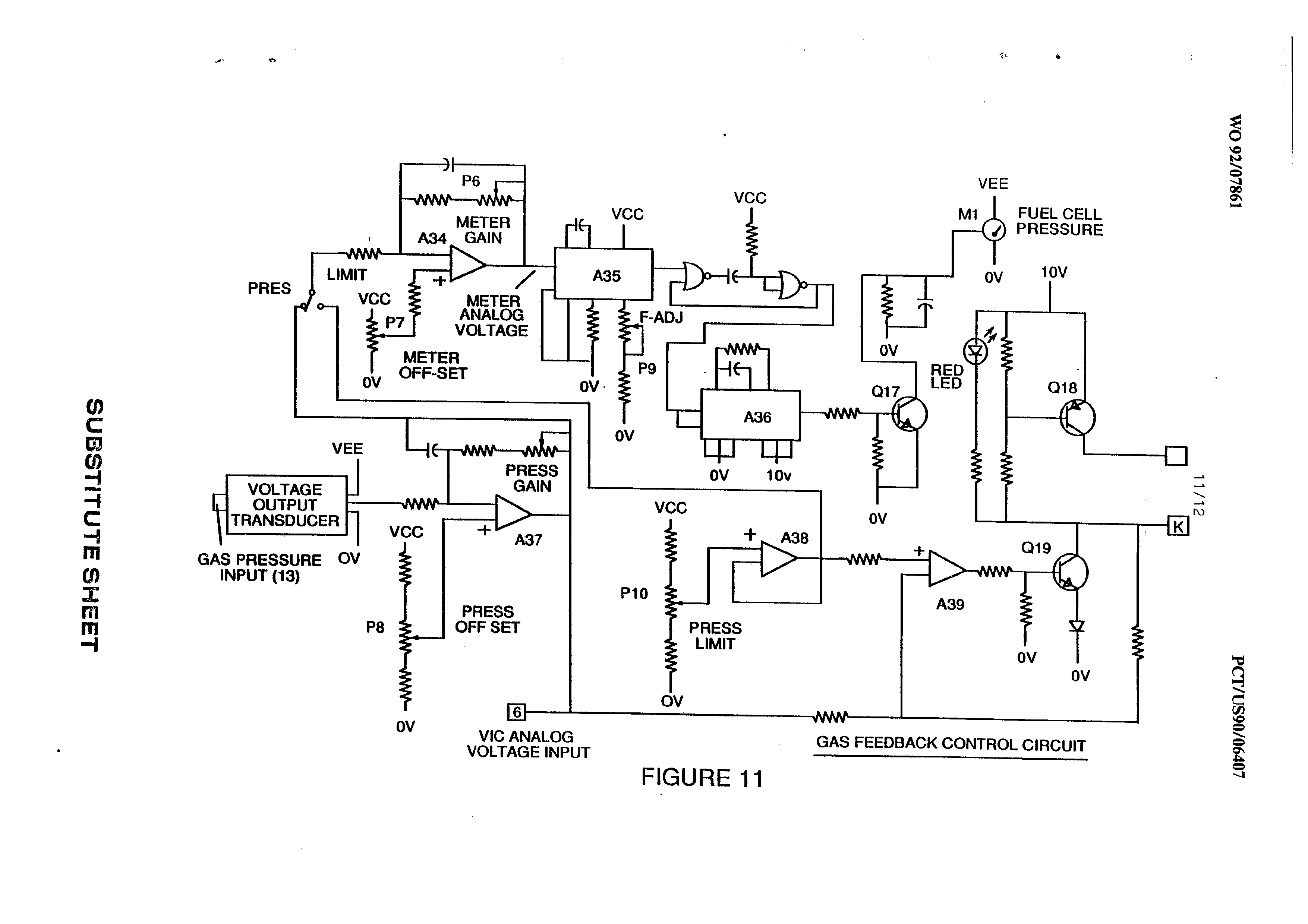
generator sent to the cell in a gated frequency in a correspondence with the rate of gas production. The sensor may be a gas pressure sensor in an enclosed water capacitor resonant cavity which also includes aé gas outlet. The gas pressure sensor is operatively connected to the circuit to determine the rate of gas production with respect to ambient gas pressure in the water capacitor enclosure.
Thus, an omnibus control circuit and its discrete elements for maintaining and controlling the resonance and other aspects of the release of gas from a resonant cavity water cell is described herein and illustrated in the
drawings which depict the following:
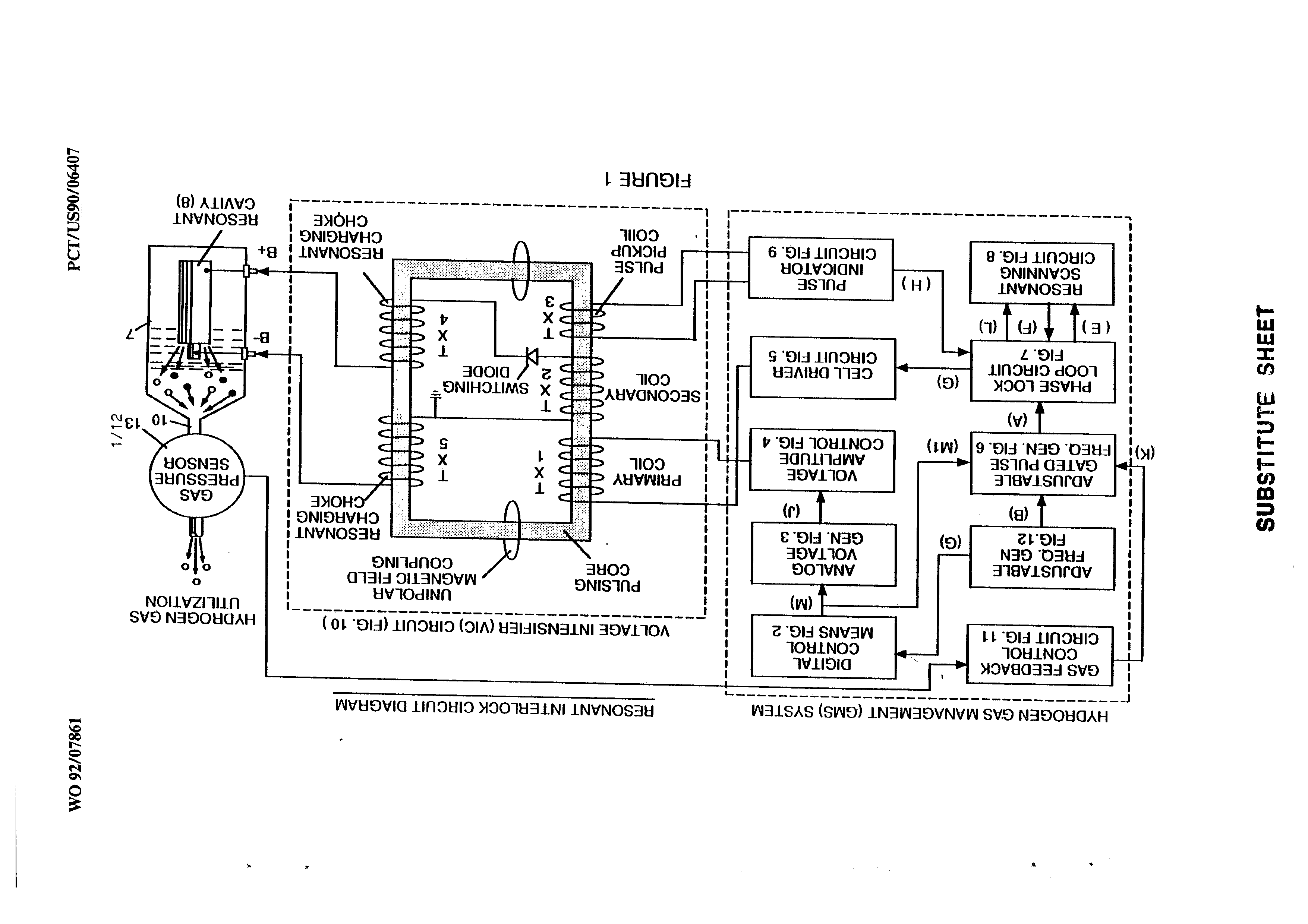
Figure 1 is a block diagram of an overall control circuit showing the interrelationship of sub-circuits, the pulsing core/resonant circuit
and the water capacitor resonant cavity.
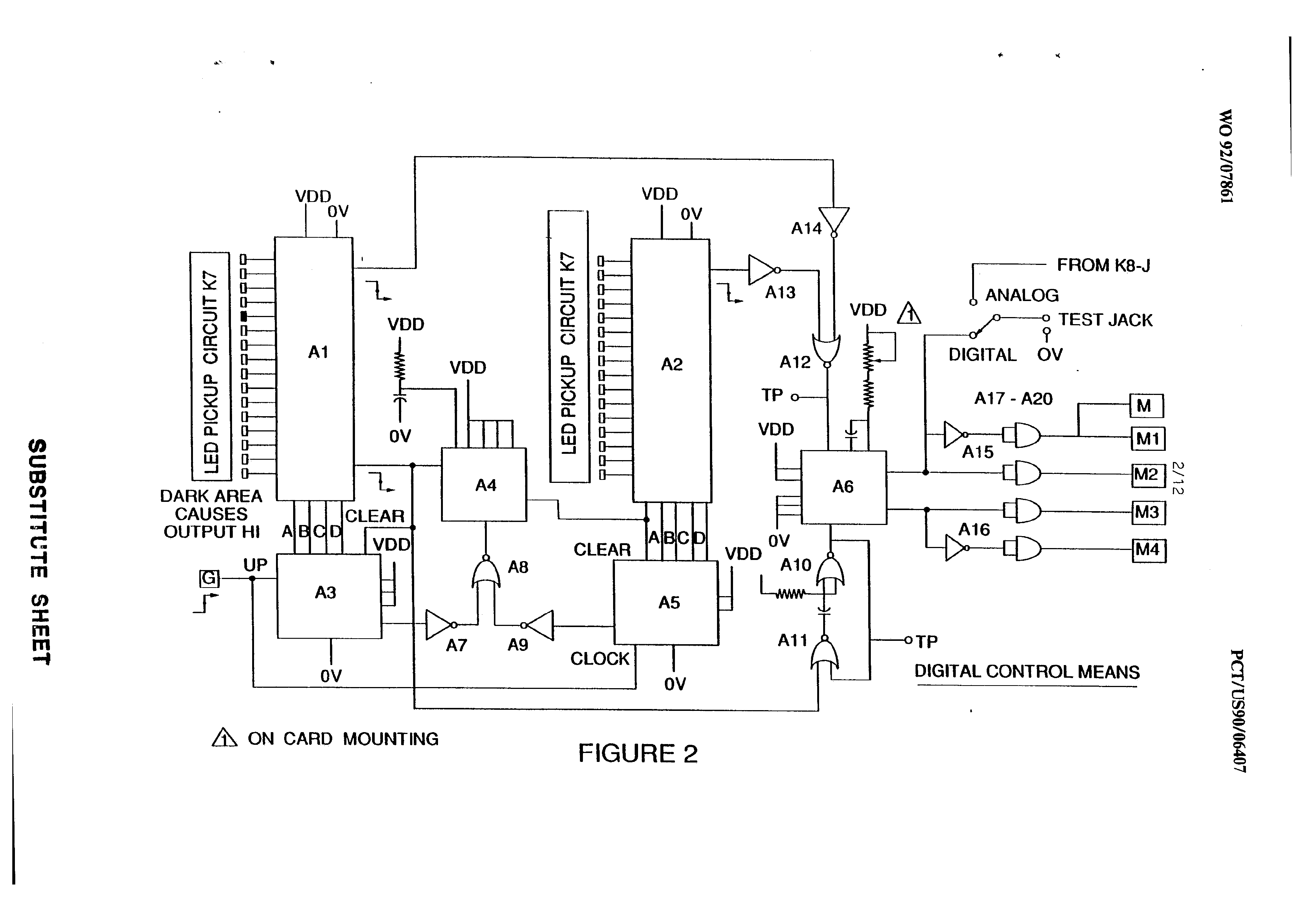
Figure 2 shows a type of digital control means for regulating the ultimate rate of gas production as determined by an external input. (Such a control means would correspond, for example, to the accelerator in an automobile or a building
thermostat control.)
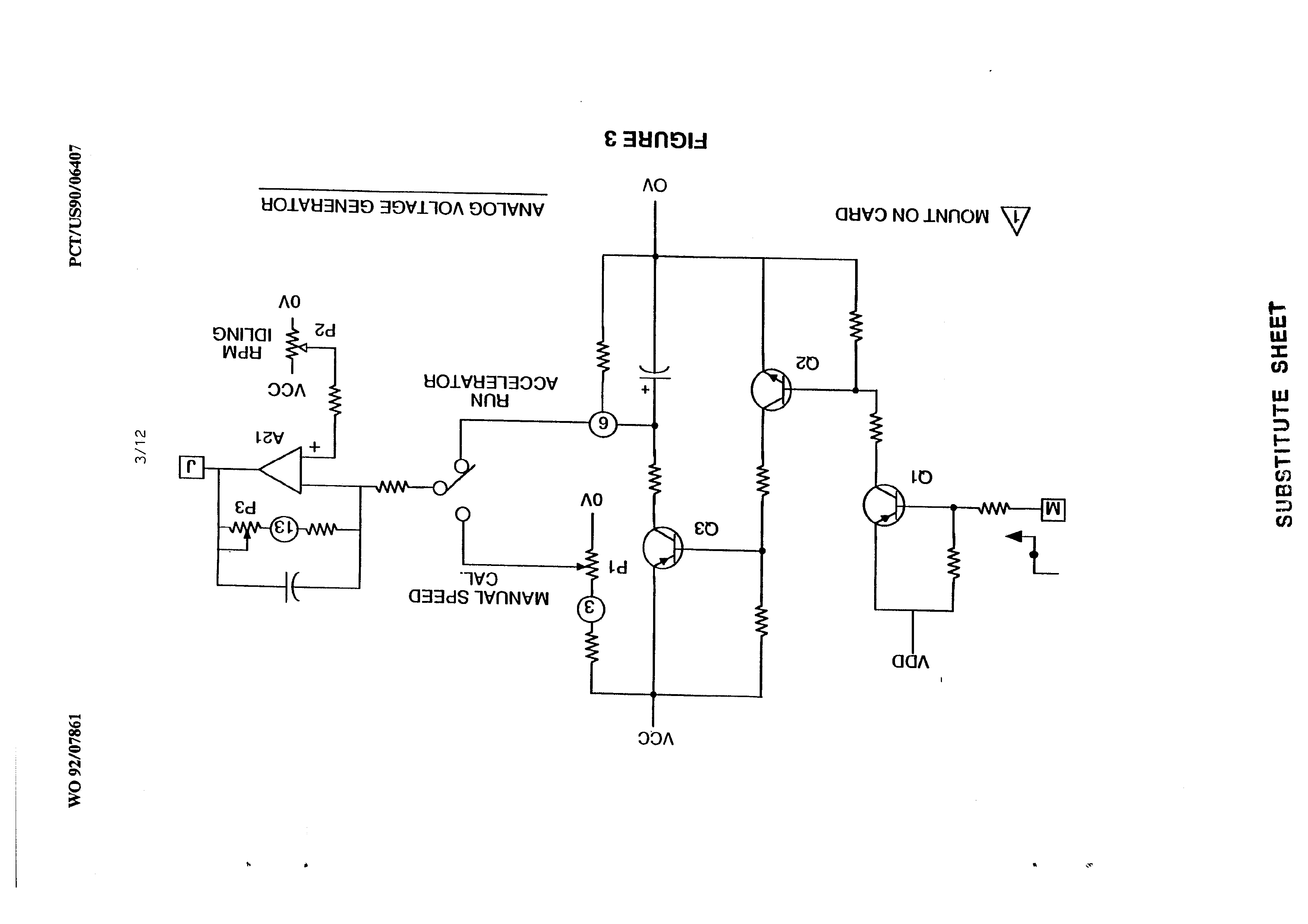
Figure 3 shows an analog voltage generator.
Page 7
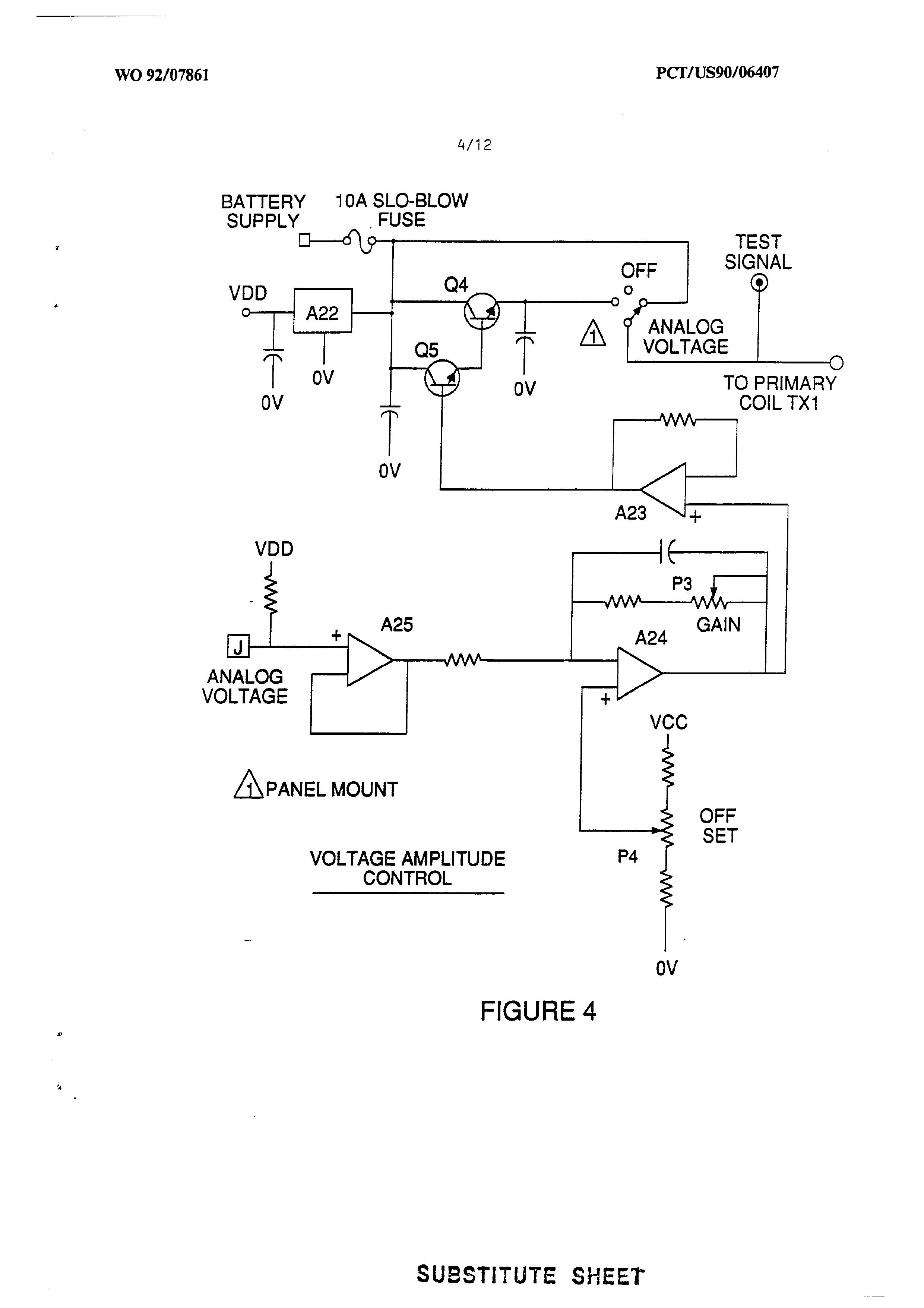
Figure 4 is a voltage amplitude control circuit interconnected with the voltage generator and one
side of the primary coil of the pulsing core.
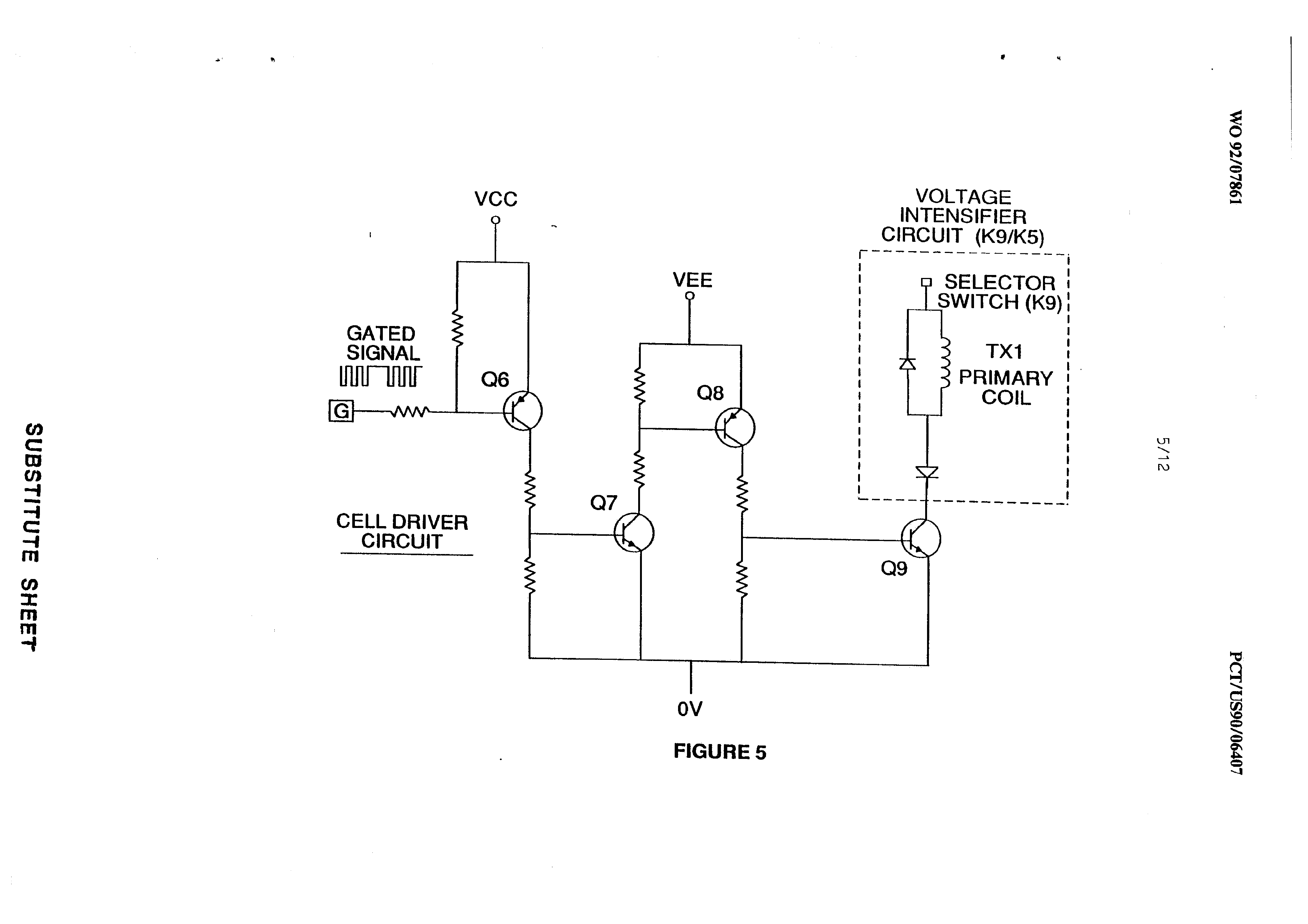
Figure 5 is the cell driver circuit that is connected with the opposite side of the primary
coil of the pulsing core.
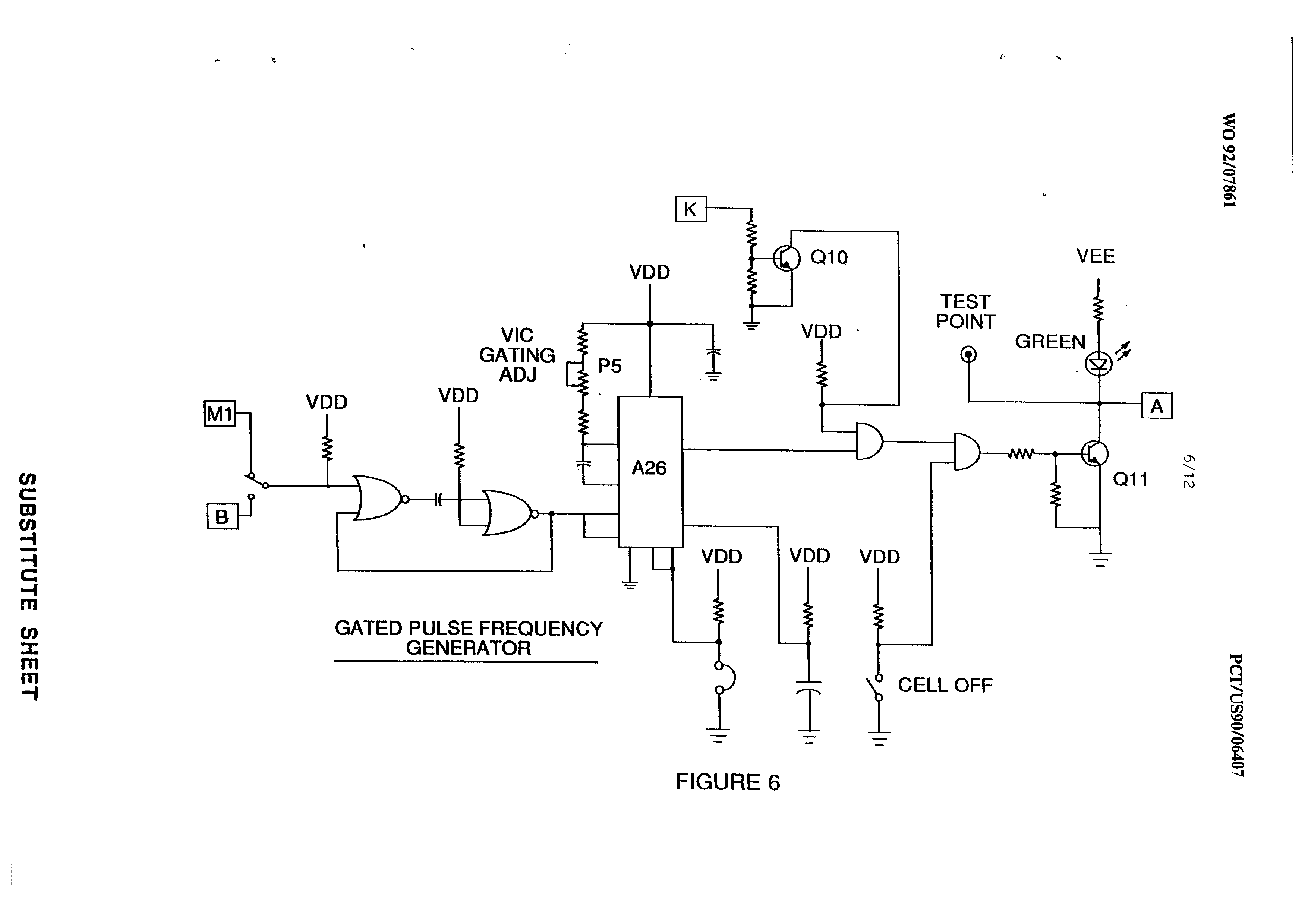
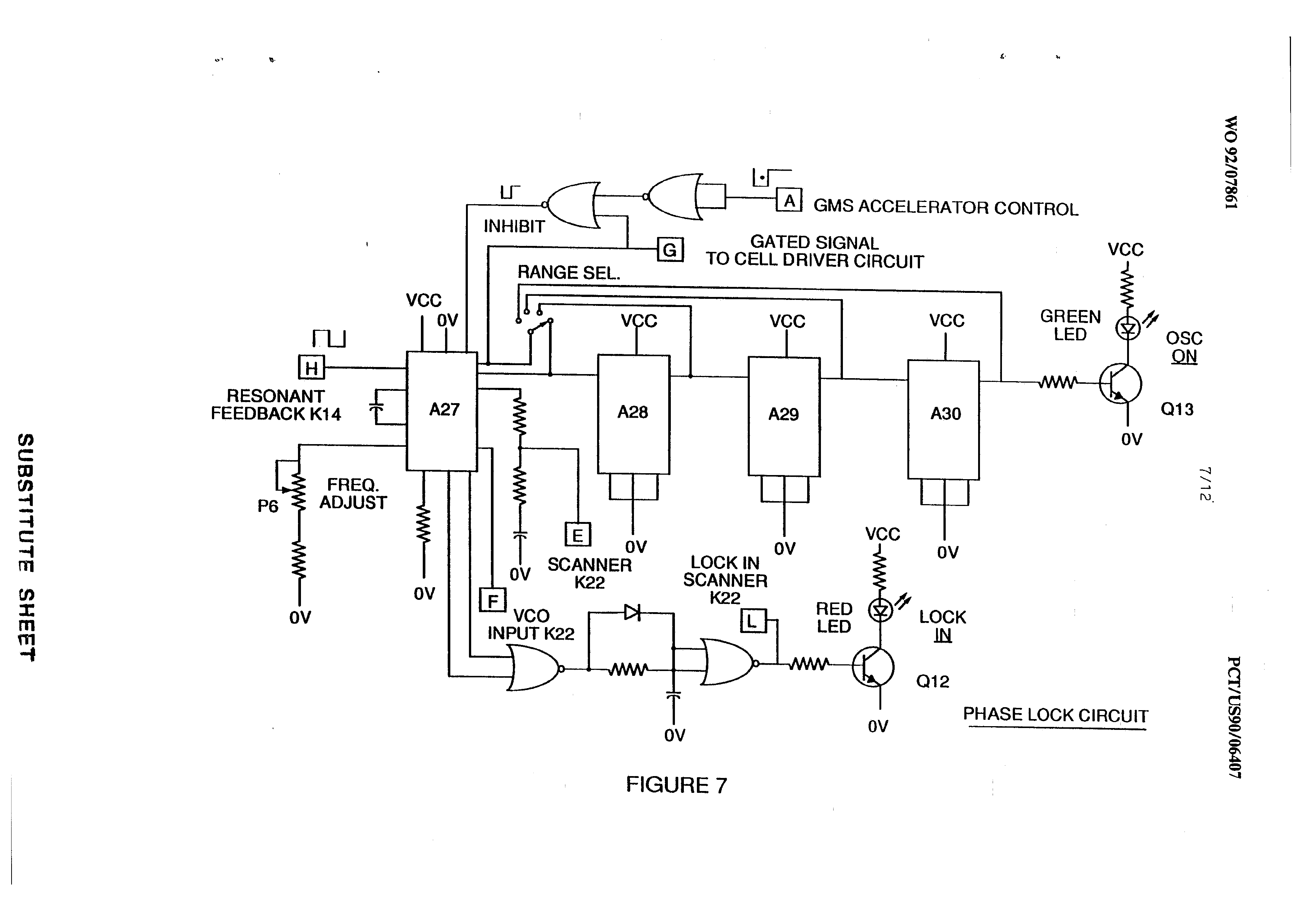
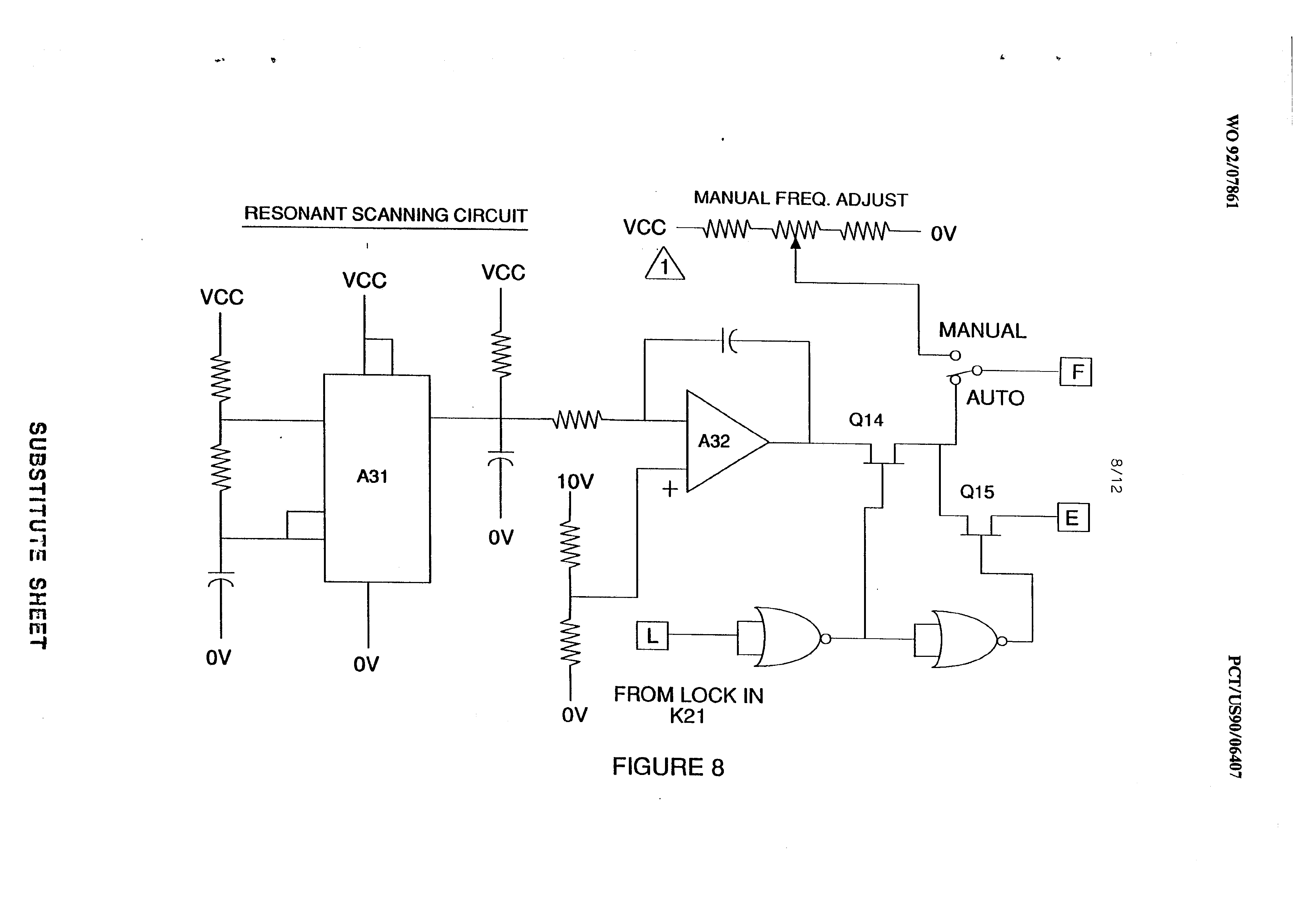
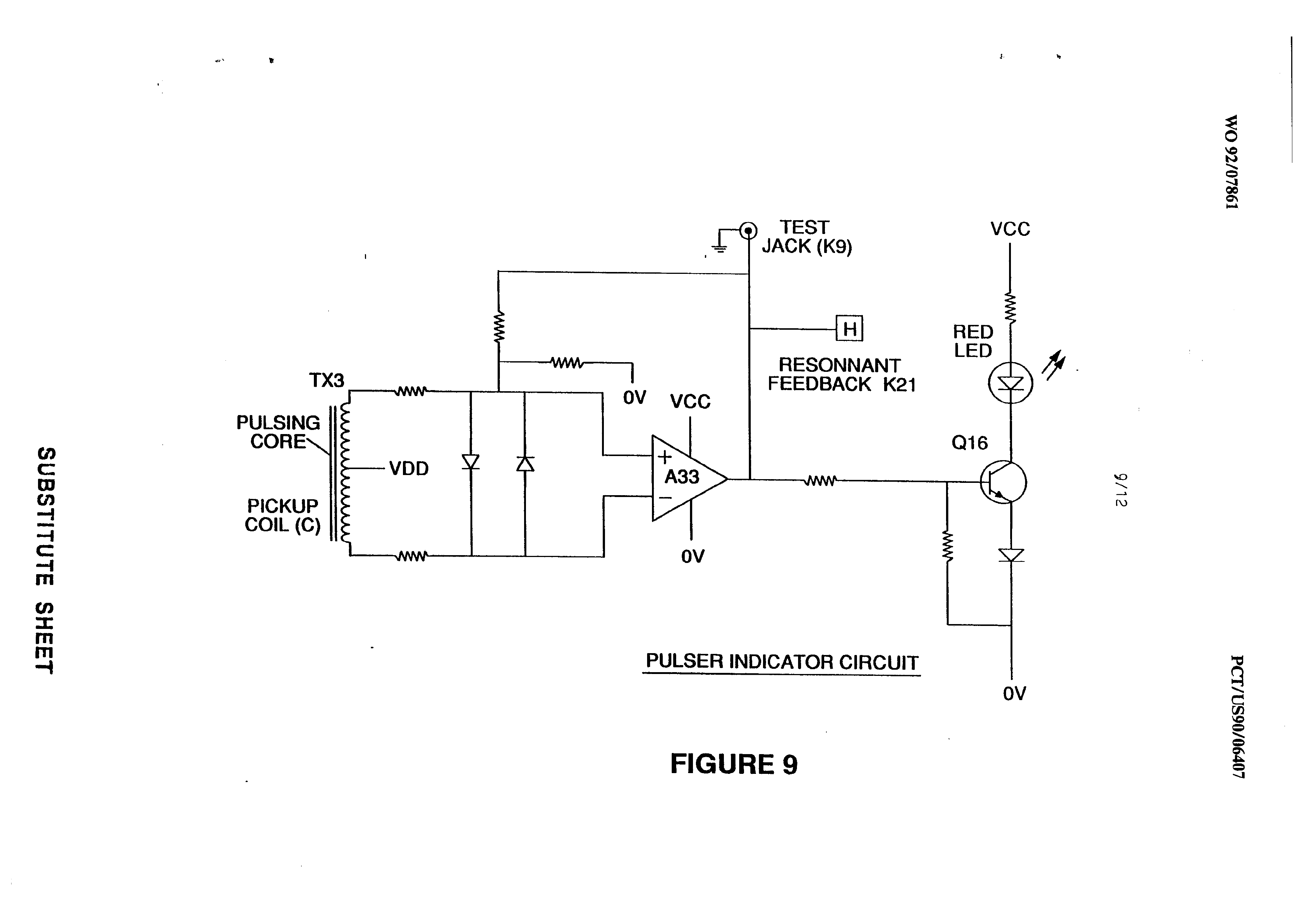
Figures 6, 7, 8 and 9 relate to pulsing control means including a gated pulse frequency generator (Figure 6); a phase lock circuit (Figure 7); a resonant scanning circuit (Figure 8); and _ the pulse indicator circuit (Figure 9) that control pulses transmitted to the resonant cavity/water
fuel cell capacitor.
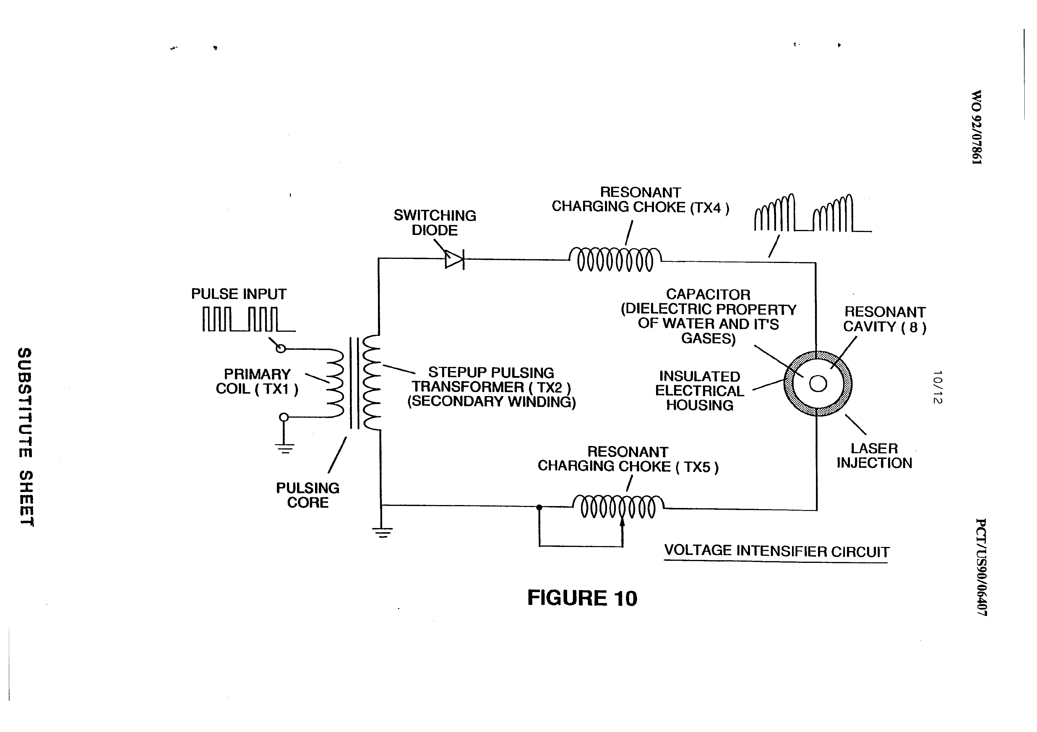
Figure 10 shows the pulsing core and the voltage intensifier circuit that is the interface between
the control circuit and the resonant cavity.
Figure 11 is a gas feedback control circuit.
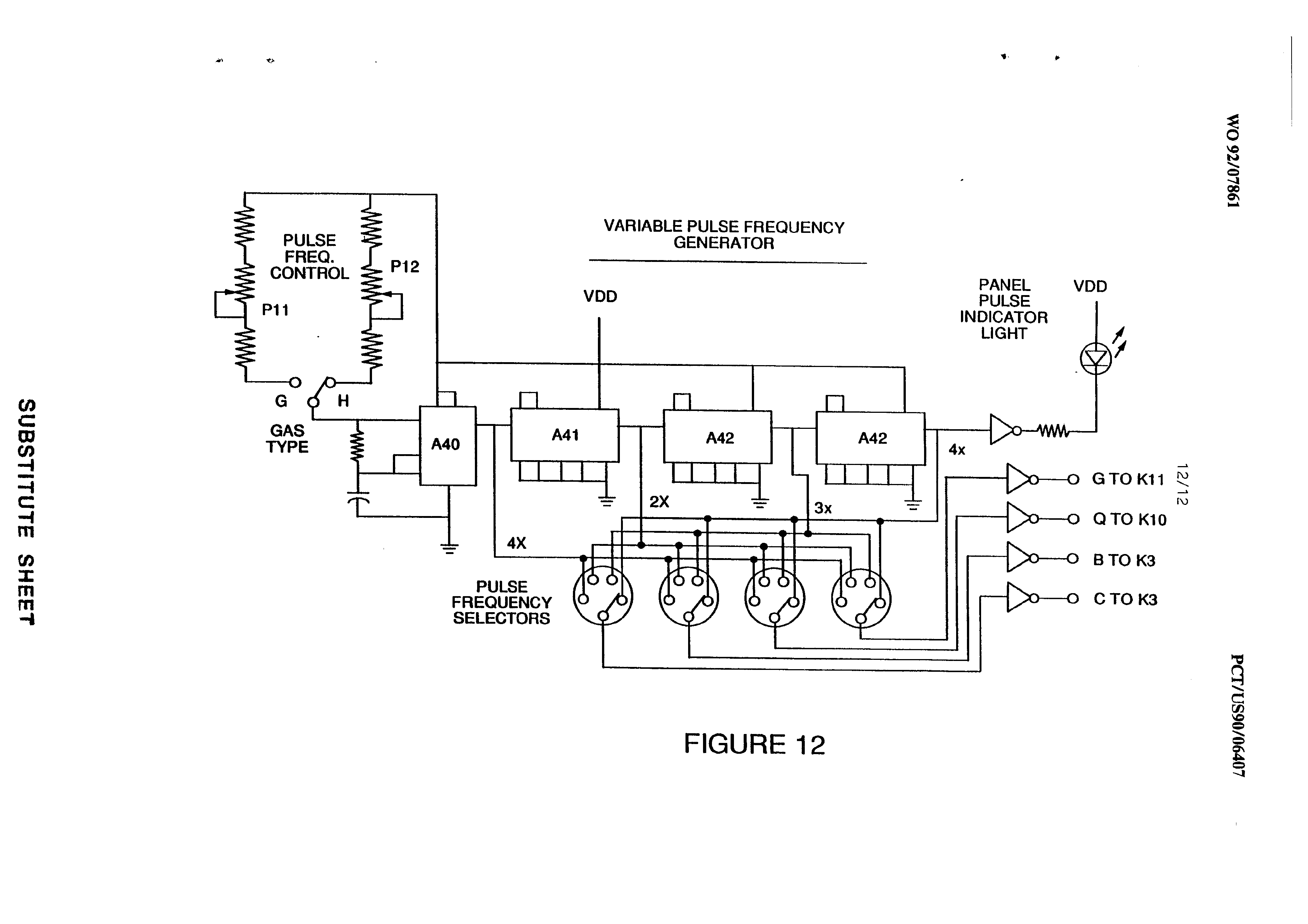
Figure 12 is an adjustable frequency generator
circuit.
The circuits are operatively interconnected as
shown in Figure 1 and to the pulsing core voltage
Page 8
intensifier circuit of Figure 10, which, inter alia,
electrically isolates the water capacitor so that it becomes an electrically isolated cavity for the processing of water in accordance with its dielectric resonance properties. By reason of the isolation, power consumption in the control and driving circuits is minimized when resonance occurs; and current demand is minimized as voltage is maximized in the gas production mode of the water capacitor/fuel cell.
The reference letters appearing in the Figures, A,
B, C, D, E, etc., to M and Ml show, with respect to each
separate circuit depicted, the point at which a connection in that circuit is made to a companion or interrelated circuit.
In the invention, the water capacitor is subjected to a duty pulse which builds up in the resonant changing choke coil and then collapses. This occurrence permits a unipolar pulse to be applied to the fuel cell capacitor. When a resonant condition of the circuit is locked-in by the circuit, amp leakage is held to a minimum as the voltage which creates the dielectric field tends to infinity. Thus, when high voltage is detected upon resonance, the phase lock loop circuit that controls the cell driver circuit maintains the resonance at the detected (or sensed) frequency.
The resonance of the water capacitor cell is
affected by the volume of water in the cell. The
Page 9
resonance of any given volume of water maintained in the water capacitor cell is also affected by "contaminants" in the water which act as a damper. For example, at an applied potential difference of 2000 to 5000 volts to the cell, an amp spike or surge may be caused by inconsistencies in water characteristics that cause an out-of-resonance condition which is remedied instantaneously by the control circuits.
In the invention, -the adjustable frequency generator (Figure 12) tunes into the resonant condition of the circuit including the water cell and the water therein. The generator has a frequency capability of O - 10 KHz and tunes into resonance typically at a frequency of 5 KHz in a typical 3.0 inch water capacitor formed of a 0.5 inch rod enclosed within a 0.75 inside diameter cylinder. At start up, in this example, current draw through the water cell will measure about 25 milliamp; however, when the circuit finds a tuned resonant condition, current drops to a 1-2 milliamp minimum leakage condition.
The voltage to the capacitor water cell increases according to the turns of the winding and size of the coils, as in a typical transformer circuit. For example, if 12 volts are sent to the primary coil of the pulsing core and the secondary coil resonant charging choke ratio
is 30 to 1, then 360 volts are sent to the capacitor water
Page 10
cell. Turns are a -design variable that control the voltage of the unipolar pulses sent to the capacitor.
The high speed switching diode shown in Figure 10 prevents charge leakage from the charged water in the water capacitor cavity, and the water capacitor as an overall capacitor circuit element, i.e., the pulse and Charge status of the water/capacitor never pass through an arbitrary ground. The pulse to the water capacitor is always unipolar. The water capacitor is electrically isolated from the control, input and driver circuits by the electromagnetic coupling through the core. The Switching diode in the VIC circuit (Figure 10) performs several functions in the pulsing. The diode is an electronic switch that determines the generation and collapse of an electromagnetic field to permit the resonant charging choke(s) to double the applied frequency and also allows the pulse to be sent to the resonant Cavity without discharging the "capacitor" therein. The diode, of course, is selected in accordance with the maximum voltage encountered in the pulsing circuit. A 600 PIV fast switching diode, such as an NVR 1550 high speed switching diode, has been found to be useful in the circuit herein.
The VIC circuit of Figure 10 also includes a ferromagnetic or ceramic ferromagnetic pulsing core capable of producing electromagnetic flux lines in
response to an electrical pulse input. The flux lines

Page 11
equally affect the ‘secondary coil and the resonant charging choke windings. Preferably, the core is a closed loop construction. The effect of the core is to isolate the water capacitor and to prevent the pulsing signal from going below an arbitrary ground and to maintain the charge of the already charged water and water capacitor.
In the pulsing core, the coils are preferably wound in the same direction to maximize the additive effect of the electromagnetic field therein.
The magnetic field of the pulsing core is in synchronization with the pulse input to the primary coil. The potential from the secondary coil is introduced to the resonant charging choke(s) series circuit elements which are subjected to the same synchronous applied electromagnetic field, simultaneously with the primary pulse.
When resonance occurs, control of the gas output is achieved by varying voltage amplitude or varying the time of duty gate cycle. The transformer core is a pulse frequency doubler. In a figurative explanation of the workings of the fuel gas generator water capacitor cell, when a water molecule is "hit" by a pulse, electron time share is affected, and the molecule is charged. When the time of the duty cycle is changed, the number of pulses that "“hit" the molecules in the fuel _ cell is correspondingly modified. More “hits" result in a greater
rate of molecular disassociation.
Page 12
With reference to the overall circuit of Figure l, Figure 3 receives a digital input signal, and Figure 4 Gepicts the control means that directs 0-12 volts across the primary coil of the pulsing core. Depending upon design parameters of primary coil voltage and other factors relevant to core design, the secondary coil of the pulsing core can be set up for a predetermined maximum, such as 2000 volts.
Figure 5, the cell driver circuit, allows a gated pulse to be varied in direct relation to voltage amplitude.
As noted above, the circuit of Figure 6 produces a gate pulse frequency. The gate pulse is superimposed over the resonant frequency pulse to create a duty cycle that determines the number of discrete pulses sent to the primary coil. For example, assuming a resonant pulse of 5 KHz, a .5 Hz gate pulse may be superimposed over the 5 KHz pulse to provide 2500 discrete pulses in a 50% duty cycle per Hz. The relationship of resonant pulse to the gate pulse is determined by conventional signal addition/subtraction techniques.
Figure 7, a phase lock loop, allows pulse frequency to be maintained at a predetermined resonant condition sensed by the circuit. Together, the circuits of Figures 7 and 8 determine an output signal to the pulsing core until the peak voltage signal sensed at
resonance is achieved.
Page 13
A resonant condition occurs when the pulse frequency and the voltage input attenuates the covalent bonding forces of the hydrogen and oxygen atoms of the water molecule. When this occurs, amp leakage through the water capacitor is minimized. The tendency of voltage to maximize at resonance increases the force of the electric potential applied to the water molecules, which ultimately disassociate into atoms.
Because resonances of different waters, water volumes, and capacitor cells vary, the resonant scanning Circuit of Figure 8 is useful. The scanning circuit of Figure 8 scans frequency from high to low to high repeating until a signal lock is determined. The ferromagnetic core of the voltage intensifier circuit transformer suppresses electron surge in an out-of-resonance condition of the fuel cell. In an example, the circuit scans at frequencies from 0 Hz to 10 KHz to 0 Hz. In water having contaminants in the range of 1 ppm to 20 ppm, a 20% variance in resonant frequency is encountered. Depending on water flow rate into fuel cell, the normal variance range is about 8-10%. For example, iron in well water affects the status of molecular disassociation. Also, at a resonant condition harmonic effects occur. In a typical operation of the cell with a representative water capacitor described below, at a frequency of about 5 KHz at unipolar pulses from 0 to 650
volts at a sensed resonant condition into the resonant
Page 14
cavity, conversion of about 5 gallons of water per hour into a fuel gas will occur on average. To increase the rate, multiple resonant cavities can be used and/or the Surfaces of the water capacitor can be increased, however, the water capacitor cell is preferably small in scale. A typical water capacitor may be formed from a 0.5 inch in diameter stainless steel rod and a 0.75 inch inside diameter cylinder that together extend concentrically about 3.0 inches with respect to each other.
Shape and size of the resonant cavity may vary. Larger resonant cavities and higher rates of consumption of water in the conversion process require higher frequencies such as up to 50 KHz and above. The pulsing rate, to sustain such high rates of conversion must be correspondingly increased.
From the foregoing description of the preferred embodiment, other variations and modifications of the System disclosed will be evident to those of skill in the
art.
Page 15
WHAT IS CLAIMED IS:
1. A control circuit for a resonant cavity water capacitor cell utilized for the production of a hydrogen
containing fuel gas including
an isolation transformer including a ferromagnetic core and having one side of a secondary coil connected in series with a high speed switching diode to one plate of the water capacitor of the resonant cavity and the other side of the secondary coil connected to the other plate of the water capacitor to form a closed loop electronic circuit utilizing the dielectric properties of water as part of the electronic circuit and a primary coil
connected to a pulse generation means.
2. The circuit of Claim 1 in which the secondary
coil includes segments that form a resonant charging choke
circuit in series with the water capacitor.
3. The circuit of Claim 1 in which the pulse generation means includes an adjustable first frequency generator and a second gated pulse frequency generator which controls the number of pulses produced by the first frequency generator sent to the primary coil during a
period determined by the gate frequency of the second
pulse generator.
Page 16
4. The circuit of Claim 1 further including a means for sensing the occurrence of a resonant condition
in the water capacitor of the resonant cavity.
5. The circuit of Claim 4 in which the means for sensing is a pickup coil on the ferromagnetic core of the
transformer.
6. The circuit of Claim 4 or Claim 5 in which the sensing means is interconnected to a scanning circuit and a phase lock loop circuit, whereby the pulsing frequency to the primary coil of the transformer is maintained at a sensed frequency corresponding to a resonant condition in
the water capacitor.
7. The circuit of Claim 1 including means for adjusting the amplitude of a pulsing cycle sent to the
primary coil.
8. The circuit of Claim 6 including further means for maintaining the frequency of the pulsing cycle at a
constant frequency regardless of pulse amplitude.
9. The circuit of Claim 3 in which the gated pulse frequency generator is operatively interconnected with a sensor that monitors the rate of gas production
from the cell and controls the number of pulses to the
Page 17
cell in a gated frequency in a correspondence with the
rate of gas production.
10. The circuit of Claim 7 or Claim 8 or Claim 9 further including a gas pressure sensor in an enclosed water capacitor resonant cavity which also includes a gas outlet, which gas pressure sensor is operatively connected to the circuit to determine the rate of gas production with respect to ambient gas pressure in the water
capacitor enclosure.
11. The methods and apparatus as substantially
described herein.
Page 18
(8) ALIAVO
INVNOSSH
NOLLVZITMLN
SVD NSDOHGAH
1 DNIDHYVHO
H 6 ‘DId LINOUIO 8 ‘Did LINDUIO
» LNVNOSSY HOLVOICNI ONINNVOS
$ ‘Did LINDHID
YAAING 1149
LINDYID dOO1
ONIHOLIMS xX
v ‘Std IOULNOO aqALNdnwy
ADVIIOA
avisnrav
JESSE eee £ Dia “N39 cl Did AINVNOSAY . FOVIIOA N39 ‘OaH4 ONIdNOO SOWNVY alavisnrav Q1Ald OILANODVW ONISTINd YVIOdINN
ee ere ee ee es ee
2 ‘Did SNVAW
TOYLNOO
WILDSIG
bE Std LINDUID
TOHLNOD
4OVEGs34 SVD
ee ere
SUBSTITUTE SHEET
Page 19
LS5SHS SLALILSENS
VDD VDD
~ lt 2 |t Lo At vob ANALOG 3 |t VDD | 0 A TEST JACK
a | ov a | VDD
DARK AREA —| As
CAUSES -— {>
OUTPUT HI AIBCD Alalcs ov | A16 \ CLEAR VDD J [e >
A7 ae A114 OTP
CLOCK (_\
ov ov DIGITAL CONTROL MEANS
ZX ON CARD MOUNTING
FIGURE 2
Page 20
Drawing sheet — no readable text.
Page 21
BATTERY 10A SLO-BLOW
SUPPLY _FUSE
_ TEST
OFF SIGNAL
| Ae | A, 7 ANALOG
VOLTAGE
OV ov TO PRIMARY OV a COIL TX1
VDD 1¢
+ ea aoa GAIN
ANALOG a 2
VOLTAGE rn vec
Z\\PANEL MOUNT
OFF
SET
VOLTAGE AMPLITUDE P4
CONTROL
FIGURE 4
SUBSTITUTE SHEET
Page 22
Drawing sheet — no readable text.
Page 23
Drawing sheet — no readable text.
Page 24
433HS Jiniiisans
RESONANT
FEEDBACK K14
ez FREQ.
pg = ADJUST
Ga GMS ACCELERATOR CONTROL a GATED SIGNAL vcc
TO CELL DRIVER CIRCUIT
GREEN 4s
VCC Vcc VCC LED 4 osc
VCC | seme’ LOCK IN ov
OV K22 SCANNER
VCO ve
INPUT K22
PHASE LOCK CIRCUIT
Page 25
Drawing sheet — no readable text.
Page 26
Drawing sheet — no readable text.
Page 27
L3SHS SLALILSENS
PULSE INPUT
PRIMARY
COIL (TX1)
PULSING
CORE
——~_ STEPUP PULSING
TRANSFORMER ( TX2 )
(SECONDARY WINDING)
RESONANT
HARGIN K
SWITCHING CHARGING CHOKE (TX<4 )
DIODE
CAPACITOR
(DIELECTRIC PROPERTY
OF WATER AND IT'S
GASES)
INSULATED
ELECTRICAL
HOUSING
RESONANT
CHARGING CHOKE ( TX5 )
RESONANT
CAVITY (8)
LASER |
INJECTION
VOLTAGE INTENSIFIER CIRCUIT
FIGURE 10
Page 28
LAaSHS ALNLILSSNs
P6 VEE
va vcc voc Mil FUEL CELL
METER (/) PRESSURE
wn P| ms | Doty " PRES } vec METER
P7 ANALOG F-ADJ
VOLTAGE =
METER po} He | RED ov OFF-SET ov. LED
VEE Ly Lo
VOLTAGE
OUTPUT > vec ov TRANSDUCER vec + +. Age
GAS PRESSURE OV >
INPUT (13)
PRESS
P8 OFF SET PRESS
| LIMIT
ov VIC ANALOG GAS FEEDBACK CONTROL CIRCUIT
VOLTAGE INPUT —
FIGURE 11
Page 29
Drawing sheet — no readable text.
Page 30
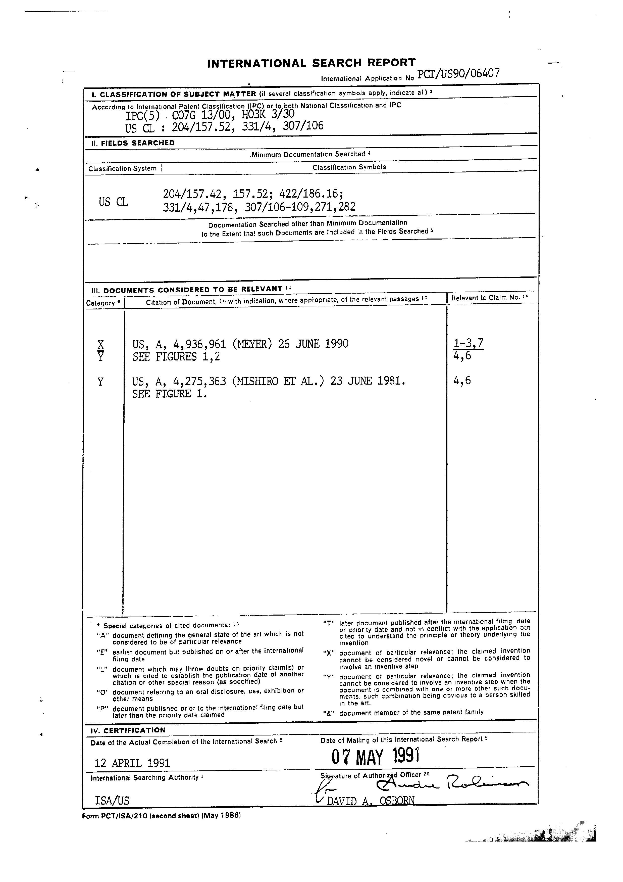
INTERNATIONAL SEARCH REPORT
International Application No
1. CLASSIFICATION OF SUBJECT MATTER (if several classification symbols apply, indicate ally 3 Accerding to International! Patent Classification (IPC) or to, both Nationa! Classification and IPC
ll. FIELOS SEARCHED
.Minimum Documentaticn Searched *
Classification System ; Classification Symbols
Documentation Searched other than Minimum Documentation to the Extent that such Documents are Included in the Fields Searched §
Il. DOCUMENTS CONSIDERED TO BE RELEVANT 3:
Citation of Document, ! with indication, where appropriate, of the relevant passages !*
| Reievant to Ciaim No. '*
Category *
Y SEE FIGURES 1,2 4,6
SEE FIGURE 1.
* Special categories of cited documents: 1% “F" later document published after the internationa) fing date van which i d notin conflict wi e application but
A” document defining the general state of the art which is not or priority date an ; considered to be of particular relevance cited to understand the principle or theory underlyirg the “E" earlier document but published on or after the international “X%"" document of particular relevance; the claimed invention filing date cannot be censidered novel or cannot be considered to “un document which may throw doubts on priority claim(s) or involve an inventive step which is cited to establish the publication date of another “Y" document of : . i i j ‘| " particular relevance; the claimed invention citation or other special reason (as specified) cannot be considered to involve an inventive step when the
document is combined with one or more other such documents, such combination being obvious to a person skilled in the art.
"&" document member of the same patent family
“O" document referring to an oral disclosure, use, exhibition or other means
"“P" document published prior to the international filing date but later than the priority date claimed
Iv, CERTIFICATION
Date of the Actual Completion of the international Search ? Date of Mailing of this International Search Report *
international Searching Authority ? Signature of Authorized Officer 2° ~
ISA/US DAVID A. OSBORN
Form PCT/ISA/210 (second sheet) (May 1986)
Provenance
- Shelf
- National filings
- Filed
- 1990-11-02
- Method
- pdftoppm 300dpi + tesseract 5 (eng), orientation-corrected
- Source
- The international pamphlet as held in the Australian file; it carries no Australian markings
- Entered From
- WO9207861A1
- Office Number
- AU-A-74852/91
- Classification
- C07G 13/00; H03K 3/30
- Application Number
- PCT/US90/06407
- International Published
- 1992-05-14